EP0358946A2 - Dispositif d'admission, respectivement de rejet d'une pièce de monnaie introduite dans un canal de payement de machine - Google Patents
Dispositif d'admission, respectivement de rejet d'une pièce de monnaie introduite dans un canal de payement de machine Download PDFInfo
- Publication number
- EP0358946A2 EP0358946A2 EP89114697A EP89114697A EP0358946A2 EP 0358946 A2 EP0358946 A2 EP 0358946A2 EP 89114697 A EP89114697 A EP 89114697A EP 89114697 A EP89114697 A EP 89114697A EP 0358946 A2 EP0358946 A2 EP 0358946A2
- Authority
- EP
- European Patent Office
- Prior art keywords
- coin
- channel
- acceptance
- lever
- flap
- Prior art date
- Legal status (The legal status is an assumption and is not a legal conclusion. Google has not performed a legal analysis and makes no representation as to the accuracy of the status listed.)
- Withdrawn
Links
Images


Classifications
-
- G—PHYSICS
- G07—CHECKING-DEVICES
- G07F—COIN-FREED OR LIKE APPARATUS
- G07F1/00—Coin inlet arrangements; Coins specially adapted to operate coin-freed mechanisms
- G07F1/04—Coin chutes
- G07F1/041—Coin chutes with means, other than for testing currency, for dealing with inserted foreign matter, e.g. "stuffing", "stringing" or "salting"
- G07F1/042—Coin chutes with means, other than for testing currency, for dealing with inserted foreign matter, e.g. "stuffing", "stringing" or "salting" the foreign matter being a long flexible member attached to a coin
- G07F1/044—Automatic detection of the flexible member
-
- G—PHYSICS
- G07—CHECKING-DEVICES
- G07D—HANDLING OF COINS OR VALUABLE PAPERS, e.g. TESTING, SORTING BY DENOMINATIONS, COUNTING, DISPENSING, CHANGING OR DEPOSITING
- G07D5/00—Testing specially adapted to determine the identity or genuineness of coins, e.g. for segregating coins which are unacceptable or alien to a currency
Definitions
- the invention relates to an acceptance or return device of a coin inserted into the coin channel of a coin-operated machine, wherein a coin gate designed as a lockable pivoting flap is provided in the coin channel, in which coins hitting the pivoting flap in the released position pivot the flap and thereby pivot into one Coin acceptance channel arrive, and the coin diverter, viewed in the direction of the coins, is arranged in front of a coin checking device.
- Such acceptance or return devices are required in coin-operated machines in order to operate in certain operating states of the machines, e.g. basic inoperability / disruptions or initiated sales or goods issue process to prevent the acceptance of coins and their supply to the coin validation facility from the outset.
- the invention is based on the object of designing a device of the type mentioned at the outset such that the coins are reliably fed to the coin acceptance channel and the subsequent coin checking device when the coin is accepted.
- a controllable pivot lever is provided with a pin-shaped extension, the pin-shaped extension in the lever position "coin acceptance” protrudes behind the coin switch / swivel flap into the coin channel and is pivoted out of the coin channel in the lever position "coin return”.
- the swivel lever is pivoted out of the coin channel in the "coin return" position, ie a pin-shaped attachment, the swivel flap is blocked, on the other hand it is ensured that coins not intended for acceptance cannot get into the coin acceptance channel and are sent to the coin return .
- the swivel lever is easily mounted in the static imbalance in such a way that it tends to swivel into the "coin return" position, another advantage can be seen in the fact that the lever can be controlled with a low energy expenditure and the arrangement thus is particularly advantageous for battery-operated machines.
- the swivel flap in the passage to the coin acceptance channel is additionally provided with a switching flag influencing an optoelectronic switch, then the correct passage of a coin can also be registered, with e.g. in the case of manipulated "thread coins” the flap cannot swivel back completely into its starting position due to the thread and the switch does not switch on / off properly.
- a switch can be used to generate a pulse when the coin is passed, and it can be sent to the coin validator.
- electronic, in particular battery-operated coin validators it is advantageous to switch this on by means of this pulse in order to save energy, i.e. when a coin is present. to activate.
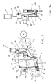
- the acceptance or return device shown in FIGS. 1 to 4 essentially consists of a coin channel 1, a swivel flap 2 and a controllable swivel lever 3.
- the coin channel is preferably designed as an inclined, rectilinear channel and in the coin channel M entered on the input side 4 rolls along the track 5 and, depending on the position of the pivot lever 3, either reach the coin accepting channel 6 on the output side or the coin return channel 7.
- the pivot lever 3 is in the position "Acceptance of coins”.
- the pivot lever is provided at its lower end 8 with a pin-shaped projection 9 which is bent so that - seen in the direction of the coin - protrudes into the coin channel behind the swivel flap 2 acting as coin switch through a slot 10 provided in the side walls of the coin channel.
- the swivel flap 2 is held smoothly in the upper bearing points 11 and its end 12, which is arranged at an angle, closes the entrance of the coin acceptance channel 6.
- the swivel flap is shaped and mounted in such a way that it always pivots in the position closing the coin acceptance channel.
- a coin M entered into the coin channel initially rolls along the track 5 until it is stopped by the shoulder 9 of the pivoting lever 3 protruding into its track.
- the coin is then on the lower end 12 of the pivoting flap and acts on the pivoting flap, which pivots it, so that the entrance to the coin acceptance channel 6 is released and the coin can fall into it. Further coin testing devices, not shown here, then adjoin the coin acceptance channel.
- the pivot lever 3 is in the "coin return” position.
- the lever which is pivotable about the bearing point 13, is rotated so that the pin-shaped projection 9 is pivoted out of the coin channel.
- a further extension 14 is formed which, in this position of the pivot lever, engages behind the pivot flap 2 in such a way that its movement is blocked and the coin acceptance channel remains closed, so that coins which roll over the pivot flap cannot open them.
- Coins entered into the coin channel thus roll freely into the coin return channel 7, from where they are fed to a coin return opening (not shown here) of the machine.
- the lever To control the pivot lever 3 in its two positions, two electromagnets 15, 16 are provided.
- the lever itself is attached to the bearing point 13.
- the bearing point is arranged with respect to the lever so that it is in static imbalance and strives to pivot gravity into the "coin return” position (see. Fig. 3).
- the lever is preferably designed as a simple, in particular light stamped and bent part, only very small forces being required to move the lever.
- the electromagnet 15 is provided for moving the lever into the "coin acceptance” position (FIG. 1).
- the armature 17 of the magnet is articulated to the swivel lever and when the magnet is energized, the armature being drawn into the magnet coil, it pulls the swivel lever into the "coin acceptance” position.
- the upper end 18 of the pivot lever 3 is step-shaped and interacts with the second electromagnet 16 or its armature 19.
- the armature 19 is held in a freely movable manner in a guide sleeve of the magnet and, when the magnet coil is not energized, rests on the upper extension 20 of the pivot lever due to its weight (FIG. 3).
- the arrangement of the swivel flap 2 is shown in a sectional view.
- the pivoting flap is provided with a switching flag 22 which actuates a switch 23 when the flap is actuated / pivoted.
- this switch is in the form of an optoelectronic light barrier, in the beam path of which the switching flag arrives when actuated.
- the pivoting flap 2 is actuated by the weight of the coin M, which exerts a force F on the flap when it is located on the lower part 12 of the pivoting flap arranged at an angle.
- the signal generated by the light barrier is preferably used to switch the coin validator on, for example by a so-called Switch "stand-by mode" (with extremely low power consumption) to the active operating state.
- the coin validator switches which is generally an electronic battery operated coin validator / vending machine trades back to the "stand-by mode".
- the side wall 24 of the coin channel is provided in the area in which the lower part 12 of the swivel flap is provided with a slit-shaped recess 25 with a height or width corresponding to the front dimensions of this part, into which the latter is immersed in the rest position of the swivel flap.
Landscapes
- Physics & Mathematics (AREA)
- General Physics & Mathematics (AREA)
- Control Of Vending Devices And Auxiliary Devices For Vending Devices (AREA)
Applications Claiming Priority (2)
| Application Number | Priority Date | Filing Date | Title |
|---|---|---|---|
| DE19883830920 DE3830920A1 (de) | 1988-09-12 | 1988-09-12 | Annahme- bzw. rueckgabevorrichtung einer in den muenzkanal eines automaten eingegebenen muenze |
| DE3830920 | 1988-09-12 |
Publications (2)
| Publication Number | Publication Date |
|---|---|
| EP0358946A2 true EP0358946A2 (fr) | 1990-03-21 |
| EP0358946A3 EP0358946A3 (fr) | 1990-09-19 |
Family
ID=6362754
Family Applications (1)
| Application Number | Title | Priority Date | Filing Date |
|---|---|---|---|
| EP19890114697 Withdrawn EP0358946A3 (fr) | 1988-09-12 | 1989-08-09 | Dispositif d'admission, respectivement de rejet d'une pièce de monnaie introduite dans un canal de payement de machine |
Country Status (2)
| Country | Link |
|---|---|
| EP (1) | EP0358946A3 (fr) |
| DE (1) | DE3830920A1 (fr) |
Cited By (2)
| Publication number | Priority date | Publication date | Assignee | Title |
|---|---|---|---|---|
| EP0511150A3 (fr) * | 1991-04-22 | 1992-12-30 | Industrias Lorenzo, S.A. | Dispositif de soutien pour appareil de validation de pièces de monnaie avec trieuse |
| DE4318858A1 (de) * | 1993-06-07 | 1994-12-08 | Nat Rejectors Gmbh | Münzprüfer mit Mitteln gegen Fadenmanipulation |
Families Citing this family (4)
| Publication number | Priority date | Publication date | Assignee | Title |
|---|---|---|---|---|
| DE4104002A1 (de) * | 1991-02-09 | 1992-08-13 | Nat Rejectors Gmbh | Annahme- und rueckgabevorrichtung fuer muenzen in einem muenzpruefer |
| DE4117096C1 (en) * | 1991-05-25 | 1992-08-06 | Harting Elektronik Gmbh, 4992 Espelkamp, De | Antitheft device recognising coin on string inserted in automat - has pendulum flap closing chute and having ribs corresp. to grooves in side wall |
| JP4542669B2 (ja) * | 2000-05-17 | 2010-09-15 | サンデン株式会社 | コイン処理装置 |
| DE10309256B4 (de) * | 2003-02-25 | 2005-03-31 | Walter Hanke Mechanische Werkstätten GmbH & Co KG | Elektronischer Münzprüfer |
Family Cites Families (2)
| Publication number | Priority date | Publication date | Assignee | Title |
|---|---|---|---|---|
| US2630200A (en) * | 1946-12-30 | 1953-03-03 | Mills Ind Inc | Coin selector |
| FR2443726A1 (fr) * | 1978-12-06 | 1980-07-04 | Vgl Ind Ltd | Appareil pour la determination de la valeur faciale de pieces de monnaie dans un mecanisme declenche par de telles pieces |
-
1988
- 1988-09-12 DE DE19883830920 patent/DE3830920A1/de active Granted
-
1989
- 1989-08-09 EP EP19890114697 patent/EP0358946A3/fr not_active Withdrawn
Cited By (2)
| Publication number | Priority date | Publication date | Assignee | Title |
|---|---|---|---|---|
| EP0511150A3 (fr) * | 1991-04-22 | 1992-12-30 | Industrias Lorenzo, S.A. | Dispositif de soutien pour appareil de validation de pièces de monnaie avec trieuse |
| DE4318858A1 (de) * | 1993-06-07 | 1994-12-08 | Nat Rejectors Gmbh | Münzprüfer mit Mitteln gegen Fadenmanipulation |
Also Published As
| Publication number | Publication date |
|---|---|
| EP0358946A3 (fr) | 1990-09-19 |
| DE3830920C2 (fr) | 1990-07-12 |
| DE3830920A1 (de) | 1990-03-15 |
Similar Documents
| Publication | Publication Date | Title |
|---|---|---|
| DE2907722C3 (de) | Allseitig geschlossenes Papierblattmagazin zum herausnehmbaren Einsetzen in eine Papierblatt-Ausgabevorrichtung | |
| DE3830920C2 (fr) | ||
| EP0173112B1 (fr) | Guidage de monnaie | |
| DE2660929C2 (de) | Selbstkassierer für Münzen | |
| EP0921501B1 (fr) | Dispositif pour le guidage de monnaies | |
| DE69012567T2 (de) | Führungsvorrichtung für Münzen. | |
| DE2326343C3 (de) | Kassiereinrichtung | |
| EP0499137B1 (fr) | Dispositif d'admission, respectivement de rejet d'une pièce de monnaie pour un appareil de contrôle de pièces de monnaie | |
| DE3810095C2 (fr) | ||
| DE2750569C3 (de) | Vorrichtung zur Sicherung von Münzkassierautomaten gegen betrügerische Handlungen | |
| DE3226737A1 (de) | Vorrichtung zur sicherung von muenz- oder jetonbetaetigten automaten gegen betruegerische handlungen | |
| DE10215467A1 (de) | Münzweiche | |
| EP2040226B1 (fr) | Dispositif destiné à trier des pièces de monnaie | |
| DE4224029C2 (de) | Münzenleitvorrichtung für einen Münzautomaten oder ein Münzspielgerät | |
| DE3045736C2 (de) | Münzprüfer für unterschiedliche Münzen | |
| DE3430072C2 (fr) | ||
| EP1145199B1 (fr) | Dispositif pour stocker et delivrer un materiau sous forme de feuilles, notamment des billets de banque, dispositif de guidage et dispositif d'acheminement pour ledit dispositif | |
| DE102008010848A1 (de) | Einwurfvorrichtung für Münzen | |
| CH624501A5 (en) | Collecting device for a coin collector | |
| CH663850A5 (de) | Muenzpruefeinrichtung. | |
| DE1114737B (de) | Vorrichtung zum Foerdern von Gegenstaenden gleicher Abmessung mittels Foerderbaender in einem Hauptkanal und mindestens einem Zufuhrkanal | |
| AT345020B (de) | Selbstkassierer fuer muenzen | |
| DE2744945A1 (de) | Muenzpruefer | |
| EP3236435A1 (fr) | Dispositif de réception verrouillable pour moyen de paiement d'une installation de traitement de véhicule | |
| DE10057238C1 (de) | Annahmeweiche |
Legal Events
| Date | Code | Title | Description |
|---|---|---|---|
| PUAI | Public reference made under article 153(3) epc to a published international application that has entered the european phase |
Free format text: ORIGINAL CODE: 0009012 |
|
| AK | Designated contracting states |
Kind code of ref document: A2 Designated state(s): AT DE ES GB NL |
|
| PUAL | Search report despatched |
Free format text: ORIGINAL CODE: 0009013 |
|
| AK | Designated contracting states |
Kind code of ref document: A3 Designated state(s): AT DE ES GB NL |
|
| 17P | Request for examination filed |
Effective date: 19901127 |
|
| 17Q | First examination report despatched |
Effective date: 19920824 |
|
| STAA | Information on the status of an ep patent application or granted ep patent |
Free format text: STATUS: THE APPLICATION HAS BEEN WITHDRAWN |
|
| 18W | Application withdrawn |
Withdrawal date: 19930407 |
|
| R18W | Application withdrawn (corrected) |
Effective date: 19930407 |