EP0359027A1 - Groupe de secours rapide pour une alimentation dynamique sans coupure - Google Patents
Groupe de secours rapide pour une alimentation dynamique sans coupure Download PDFInfo
- Publication number
- EP0359027A1 EP0359027A1 EP89115950A EP89115950A EP0359027A1 EP 0359027 A1 EP0359027 A1 EP 0359027A1 EP 89115950 A EP89115950 A EP 89115950A EP 89115950 A EP89115950 A EP 89115950A EP 0359027 A1 EP0359027 A1 EP 0359027A1
- Authority
- EP
- European Patent Office
- Prior art keywords
- generator
- flywheel
- flywheel system
- clutch
- unit according
- Prior art date
- Legal status (The legal status is an assumption and is not a legal conclusion. Google has not performed a legal analysis and makes no representation as to the accuracy of the status listed.)
- Granted
Links
Images


Classifications
-
- H—ELECTRICITY
- H02—GENERATION; CONVERSION OR DISTRIBUTION OF ELECTRIC POWER
- H02J—ELECTRIC POWER NETWORKS; CIRCUIT ARRANGEMENTS OR SYSTEMS FOR SUPPLYING OR DISTRIBUTING ELECTRIC POWER; SYSTEMS FOR STORING ELECTRIC ENERGY
- H02J3/00—Circuit arrangements for AC mains or AC distribution networks
- H02J3/28—Arrangements for balancing of the load in networks by storage of energy
- H02J3/30—Arrangements for balancing of the load in networks by storage of energy using dynamo-electric machines coupled to flywheels
-
- H—ELECTRICITY
- H02—GENERATION; CONVERSION OR DISTRIBUTION OF ELECTRIC POWER
- H02J—ELECTRIC POWER NETWORKS; CIRCUIT ARRANGEMENTS OR SYSTEMS FOR SUPPLYING OR DISTRIBUTING ELECTRIC POWER; SYSTEMS FOR STORING ELECTRIC ENERGY
- H02J9/00—Circuit arrangements for emergency or stand-by power supply, e.g. for emergency lighting
- H02J9/04—Circuit arrangements for emergency or stand-by power supply, e.g. for emergency lighting in which the distribution system is disconnected from the normal source and connected to a standby source
- H02J9/06—Circuit arrangements for emergency or stand-by power supply, e.g. for emergency lighting in which the distribution system is disconnected from the normal source and connected to a standby source with automatic change-over, e.g. UPS systems
- H02J9/066—Circuit arrangements for emergency or stand-by power supply, e.g. for emergency lighting in which the distribution system is disconnected from the normal source and connected to a standby source with automatic change-over, e.g. UPS systems characterised by the use of dynamo-electric machines
-
- Y—GENERAL TAGGING OF NEW TECHNOLOGICAL DEVELOPMENTS; GENERAL TAGGING OF CROSS-SECTIONAL TECHNOLOGIES SPANNING OVER SEVERAL SECTIONS OF THE IPC; TECHNICAL SUBJECTS COVERED BY FORMER USPC CROSS-REFERENCE ART COLLECTIONS [XRACs] AND DIGESTS
- Y02—TECHNOLOGIES OR APPLICATIONS FOR MITIGATION OR ADAPTATION AGAINST CLIMATE CHANGE
- Y02B—CLIMATE CHANGE MITIGATION TECHNOLOGIES RELATED TO BUILDINGS, e.g. HOUSING, HOUSE APPLIANCES OR RELATED END-USER APPLICATIONS
- Y02B70/00—Technologies for an efficient end-user side electric power management and consumption
- Y02B70/30—Systems integrating technologies related to power network operation and communication or information technologies for improving the carbon footprint of the management of residential or tertiary loads, i.e. smart grids as climate change mitigation technology in the buildings sector, including also the last stages of power distribution and the control, monitoring or operating management systems at local level
-
- Y—GENERAL TAGGING OF NEW TECHNOLOGICAL DEVELOPMENTS; GENERAL TAGGING OF CROSS-SECTIONAL TECHNOLOGIES SPANNING OVER SEVERAL SECTIONS OF THE IPC; TECHNICAL SUBJECTS COVERED BY FORMER USPC CROSS-REFERENCE ART COLLECTIONS [XRACs] AND DIGESTS
- Y02—TECHNOLOGIES OR APPLICATIONS FOR MITIGATION OR ADAPTATION AGAINST CLIMATE CHANGE
- Y02E—REDUCTION OF GREENHOUSE GAS [GHG] EMISSIONS, RELATED TO ENERGY GENERATION, TRANSMISSION OR DISTRIBUTION
- Y02E60/00—Enabling technologies; Technologies with a potential or indirect contribution to GHG emissions mitigation
- Y02E60/16—Mechanical energy storage, e.g. flywheels or pressurised fluids
-
- Y—GENERAL TAGGING OF NEW TECHNOLOGICAL DEVELOPMENTS; GENERAL TAGGING OF CROSS-SECTIONAL TECHNOLOGIES SPANNING OVER SEVERAL SECTIONS OF THE IPC; TECHNICAL SUBJECTS COVERED BY FORMER USPC CROSS-REFERENCE ART COLLECTIONS [XRACs] AND DIGESTS
- Y04—INFORMATION OR COMMUNICATION TECHNOLOGIES HAVING AN IMPACT ON OTHER TECHNOLOGY AREAS
- Y04S—SYSTEMS INTEGRATING TECHNOLOGIES RELATED TO POWER NETWORK OPERATION, COMMUNICATION OR INFORMATION TECHNOLOGIES FOR IMPROVING THE ELECTRICAL POWER GENERATION, TRANSMISSION, DISTRIBUTION, MANAGEMENT OR USAGE, i.e. SMART GRIDS
- Y04S20/00—Management or operation of end-user stationary applications or the last stages of power distribution; Controlling, monitoring or operating thereof
- Y04S20/20—End-user application control systems
Definitions
- the invention relates to an electrical unit according to the preamble of claim 1.
- the clutch between the flywheel and the synchronous reversing machine is closed in order to transmit the energy of the flywheel to the synchronous reversing machine and to maintain the drive until the load can be taken over by the internal combustion engine.
- This known structure does not allow controllable energy transfer from the energy store to the generator drive, since the clutch does not allow metered, controllable energy transfer from the flywheel to the generator drive.
- the clutch only allows a cyclical actuation, which means that no constant, ie. H. no narrow frequency band energy conversion can be achieved.
- the clutch which is designed as a friction clutch, has limits when it comes to the transmission of energy or torque. It is therefore essential that there is a coordination between the excess energy in the flywheel and the clutch design, so that there is no overstressing of the clutch and a possible failure.
- the invention is therefore based on the object of providing a frequency matching the normal operation of the generator when the stored energy is transferred to the generator or generator drive and, if necessary, the entire storage energy can be used to maintain the predetermined frequency on the drive of the power generator.
- the immediate standby unit according to the invention makes use of a known physical connection.
- the structure of the immediate standby unit according to the invention provides that the flywheel systems serving as energy stores rotate at a much higher speed than the speed of the generator.
- a special induction clutch is used as the clutch, by means of which contactlessly arranged runners are coupled in alignment on two separate shafts. It should be emphasized in particular that such a coupling advantageously enables an ideally controllable flow of force between two rotating components (shafts).
- This clutch allows energy to be transferred from the high-speed flywheel system over a longer period of time to the shaft of the synchronous reversing machine rotating at a lower speed. This allows a controllable energy flow while maintaining a predetermined frequency up to a frequency bandwidth of ⁇ 1% for an uninterruptible power supply.
- the induction coupling itself provides two independent runners arranged radially to one another.
- the structure of the clutch advantageously allows all of the stored energy to be transferred to the generator drive, since the power flow between the two runners of the induction coupling takes place without contact and consequently there is no mechanical overloading of the coupling.
- the use of this induction coupling according to the invention allows a much higher storage energy in the form of flywheel systems than is required for driving the generator, so as to have sufficient drive energy for the generator for a larger period of time due to the larger stored energy volume until the load is taken over through the diesel engine.
- the invention further provides that the rotor arrangement is selected so that a rotor is enclosed radially without contact by the counter rotor.
- the induction coupling through which the stored energy is transmitted if necessary, therefore has the task of ensuring frequency control in the event of a power failure of the generator drive, in addition to the energy transmission by coupling the rotors with the aid of an induction current.
- an electronic control arranged with the clutch is suitable.
- a certain pre-excitation of the induction coupling ensures that, if necessary, the shortest possible transmission of the total energy to the generator drive, ie achievable in the range of milliseconds, can be achieved.
- the speed can thus be ideally controlled at a predetermined frequency. Furthermore, it can achieve compliance with a fixed speed ratio during normal operation between the flywheel systems.
- the idea of the invention also provides that the flywheel system, which is constantly connected to the synchronous reversing machine, is arranged within a transmission and is translated into high speed, ie to a higher speed. Resulting from the transmission advantageous the possibility to shorten the overall length of the unit and to reduce the volume and weight due to the high-speed rotating, relatively light weight flywheel systems.
- the transmission is advantageously constructed so that several flywheel systems can be arranged, for example, in a star shape around a central central gear.
- an electric motor with a central, centrally arranged motor is advantageous, from which the high-speed drive takes place by means of a belt or wheel drive.
- a combination of individual electric motors with a single flywheel is also conceivable.
- the separately driven flywheel system is overhung to achieve the shortest possible overall length of the unit.
- this design can be realized in connection with flywheel systems arranged directly on the shaft of the electric motor at a short distance therefrom, advantageously by a combination combined to form a unit - electric motor and flywheel.
- the speed of the separately driven flywheel system is designed to be more than twice as high as that of the synchronous reversing machine and that the speed ratio between the rigidly driven flywheel system connected to the generator drive and the synchronous reversing machine is 5: 1 is. This enables high differential speeds to be achieved and thus long-lasting energy transmission with improved efficiency.
- FIG. 1 shows a conventionally constructed immediate standby unit, in which all individual components are aligned on the base frame 14 in one axis.
- the structure is characterized by a large, continuously rotating flywheel 9, which is provided on both sides with bearings 8 and is normally driven by the electric motor 11 via the elastic coupling 10.
- the electric motor 11 On the side of the electric motor 11 opposite the flywheel 9, the electric motor 11 is connected to the generator 13 via the elastic coupling 12.
- the diesel engine 5 is started automatically as a function of a predetermined frequency deviation and provides the necessary drive for the generator 13. Until the load on the diesel engine 5, the large rotating flywheel 9 ensures that there is no complete voltage drop.
- the diesel engine 5 is arranged at the opposite end of the base frame 14 as seen from the generator 13 and can be coupled to the flywheel 9 via an elastic coupling 6 and a clutch 7.
- this known construction requires a large amount of energy to drive the large flywheel 9.
- FIG. 2 describes an immediate standby unit according to the invention for an uninterruptible power supply.
- the individual components of the unit are shown in simplified form in a plan view.
- a synchronous reversing machine 34 is provided, or alternatively a separate synchronous motor and synchronous generator in one Casing.
- the synchronous reversing machine 34 is constantly coupled to the gear 36 via an elastic coupling 35, which serves, inter alia, as an energy store.
- the transmission 36 has two output shafts 44 on the longitudinal axis of which the elastic coupling 37 and an adjustable induction coupling serving as a switching clutch 38 and an electric motor 39 serving to drive the flywheel system 42 are arranged.
- an electromagnetically actuated clutch 33 is initially provided on the longitudinal axis 28, via which, if necessary, the auxiliary drive - the diesel motor 30 - can be coupled to the synchronous reversing machine 34.
- an elastic coupling 31 and an intermediate bearing 32 are provided between the diesel engine 30 and the clutch 33.
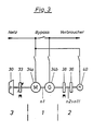
- FIG. 3 shows in simplified form, with the help of a schematic representation, the immediate readiness unit according to the invention, which can be divided into three system components.
- the system component 1 includes the electric motor 34a denoted by M and the generator or synchronous reversing machine 34b denoted by G, which normally ensures the mains supply for the consumers. In the event of a power failure and thus the generator 34b not being driven, the generator 34b is driven for a bridging time via the system component 2.
- This consists of the electric motor 40, which has a flywheel and is coupled to the transmission 36.
- flywheel system which serves as an energy store and which, depending on need, can be used with the aid of the clutch 38 to temporarily drive the generator 34b in order to reduce the speed of the system too much to avoid component 1, ie the generator 34b.
- the diesel engine 30 starts automatically, which can take over the drive of the generator 34b when the load is fully taken up by an electromagnetically actuated clutch 33.
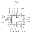
- FIG. 4 shows a detailed structure of the system component 2 according to FIG. 3, which represents a possible mechanical construction.
- the electric motor 40 arranged centrally on the longitudinal axis 28 at one end of the system component 2 drives via V-belts 50 two connecting shafts 52 arranged parallel to the longitudinal axis 28, on which, viewed from the V-belt drive, first the flywheel system 49 and then the clutch 38 are connected in a rotationally fixed manner.
- the connecting shaft 52 can be coupled to the input shaft 44 emerging from the transmission 36 if necessary.
- the gears 51 are attached in a rotationally fixed manner, which are toothed with the gear 45 located centrally in the gear 36 on the input shaft 43.
- Another gear 46 also rotatably connected to the output shaft 43 and arranged parallel to the gear 45, serves to drive two pinions 47, each of which is connected to a downstream flywheel system 48 in a rotationally fixed manner and rotate at high speed due to a translation into high speed.
- This representation clearly shows the structure which requires little installation space as a result of the parallel arrangement and the flywheel system rotating at high speed.
- the structure also shows a separate drive from the flywheel system 48 and 49.
- the gear (45) is driven in the dot-dash ge drew gear 36 by driving the synchronous reversing machine via the input shaft (43).
- the flywheel system 49 is constantly driven by the separately arranged electric motor 40.
- the synchronous reversing machine 34 is connected to the network as an electric motor, and the shaft speed for a 50 Hz unit is 1500 rpm.
- the switching clutches 38 designed as induction clutches permit a speed difference due to a slight pre-excitation of the induction coupling between the output shaft 44 (speed 2000 / min.) And the connecting shaft) 52 (speed 4000 / min.) Arranged in alignment. Since no auxiliary or emergency drive is required in this operation, the diesel engine 30 is stopped, the clutch 33 being open.
- the clutches 38 are energized, which build up 110% of the required nominal torque within a time of approximately 100 ms and thus ensure the required generator drive.
- the flywheel system 48 integrated in the transmission 36 keeps the speed drop of the synchronous reversing machine 34 within permissible limits.
- the electric motor 39 connected to the flywheel system 42 ensures the energy supply until the diesel engine 30 takes over the load completely.
- the clutch 33 is closed for load transfer by the diesel engine 30.
- the frequency quality is achieved by the electronically controllable clutch 38 acting as an induction clutch, as a result of which a dynamic change in speed under different load conditions can be kept within a permissible frequency tolerance band of 50 Hz plus minus 1%. Under full load conditions, this can lead to the reduction of the excess energy of the flywheel system 42 or the achievement of a speed match between the synchronous reversing machine 34 and the flywheel system 42.
- the clutches 38 are switched off and the electric motor 39 provides for the required speed increase to 4000 rpm. of the flywheel systems 42.
- the synchronous reversing machine 34 is synchronized in generator mode from the diesel engine to the mains and the load to the mains switched. After a certain run-on time, the diesel engine 30 is switched off and the clutches 38 in turn receive a low pre-excitation for the speed difference between the output shaft 44 from the transmission 36 and the speed of the electric motor 39.
- the synchronous reversing machine 34 now works independently again and the electric motor 39 is connected with the flywheel system 42 are thus ready again by the clutch 38, with which the energy store consisting of the electric motor 39 and the flywheel system 42 can be switched on for a short time if necessary.
Landscapes
- Engineering & Computer Science (AREA)
- Power Engineering (AREA)
- Business, Economics & Management (AREA)
- Emergency Management (AREA)
- Stand-By Power Supply Arrangements (AREA)
- Connection Of Motors, Electrical Generators, Mechanical Devices, And The Like (AREA)
- Hybrid Electric Vehicles (AREA)
- Electric Propulsion And Braking For Vehicles (AREA)
- Electrophotography Configuration And Component (AREA)
Priority Applications (1)
| Application Number | Priority Date | Filing Date | Title |
|---|---|---|---|
| AT89115950T ATE96585T1 (de) | 1988-08-31 | 1989-08-30 | Sofortbereitschaftsaggregat fuer eine dynamische, unterbrechungsfreie stromversorgung. |
Applications Claiming Priority (2)
| Application Number | Priority Date | Filing Date | Title |
|---|---|---|---|
| DE3829457 | 1988-08-31 | ||
| DE3829457A DE3829457A1 (de) | 1988-08-31 | 1988-08-31 | Sofortbereitschaftsaggregat fuer eine dynamische, unterbrechungsfreie stromversorgung |
Publications (2)
| Publication Number | Publication Date |
|---|---|
| EP0359027A1 true EP0359027A1 (fr) | 1990-03-21 |
| EP0359027B1 EP0359027B1 (fr) | 1993-10-27 |
Family
ID=6361928
Family Applications (1)
| Application Number | Title | Priority Date | Filing Date |
|---|---|---|---|
| EP89115950A Expired - Lifetime EP0359027B1 (fr) | 1988-08-31 | 1989-08-30 | Groupe de secours rapide pour une alimentation dynamique sans coupure |
Country Status (3)
| Country | Link |
|---|---|
| EP (1) | EP0359027B1 (fr) |
| AT (1) | ATE96585T1 (fr) |
| DE (2) | DE3829457A1 (fr) |
Cited By (8)
| Publication number | Priority date | Publication date | Assignee | Title |
|---|---|---|---|---|
| FR2783367A1 (fr) * | 1998-09-14 | 2000-03-17 | Air Liquide | Systeme d'alimentation en energie electrique pour appareillage electrique |
| RU2253741C2 (ru) * | 2003-06-16 | 2005-06-10 | ООО "Инжиниринговый центр "Звезда" | Способ функционирования автономной электростанции |
| EP1890371A1 (fr) * | 2006-08-03 | 2008-02-20 | Michael J. Mosman | Configuration de système UPS se composant de modules parallèles et indépendants |
| EP2595266A1 (fr) | 2011-11-18 | 2013-05-22 | GE Energy Products France SNC | Installation de production d'énergie électrique dotée de moyens de stockage d'énergie et procédé de commande d'une telle installation |
| GB2519116A (en) * | 2013-10-10 | 2015-04-15 | William Brian Turner | Rapid on-line power reversal control device for flywheel electrical energy storage |
| US10135293B2 (en) | 2015-04-01 | 2018-11-20 | Isolated Parallel Inc | Direct current isolated-parallel uninterruptible power supply system |
| BE1026837B1 (fr) * | 2018-12-05 | 2020-07-06 | Kinolt | Génératrice d'électricité |
| DE102022106633A1 (de) | 2022-03-22 | 2023-09-28 | TenneT TSO GmbH | Verbund aus einem elektrischen Netzwerk, einem Kraftwerk sowie einem Speicherkraftwerk sowie Verfahren zum Ausgleich einer fluktuierenden Leistungsbereitstellung des Kraftwerks |
Families Citing this family (3)
| Publication number | Priority date | Publication date | Assignee | Title |
|---|---|---|---|---|
| RU2295817C2 (ru) * | 2005-05-13 | 2007-03-20 | Новосибирский государственный технический университет | Способ повышения динамической устойчивости синхронных электрических машин |
| DE102010022548A1 (de) | 2010-06-02 | 2011-12-08 | Schaeffler Technologies Gmbh & Co. Kg | Luftfahrzeug und Stromversorgungseinheit hierfür |
| DE102022107537A1 (de) | 2022-03-30 | 2023-10-05 | Technische Universität Ilmenau, Körperschaft des öffentlichen Rechts | Stromaggregat und Verfahren zur Erzeugung von elektrischem Strom mit konstanter Netzfrequenz |
Citations (2)
| Publication number | Priority date | Publication date | Assignee | Title |
|---|---|---|---|---|
| DE1944663B2 (de) * | 1969-09-03 | 1970-10-29 | Dynamics Corp America | Notstromaggregat |
| DE1765958A1 (de) * | 1968-08-16 | 1971-11-25 | Licentia Gmbh | Bereitschaftsanlage zur Stromversorgung von Verbrauchern bei Netzausfall |
Family Cites Families (4)
| Publication number | Priority date | Publication date | Assignee | Title |
|---|---|---|---|---|
| FR1138677A (fr) * | 1955-12-20 | 1957-06-18 | Groupe électrogène à débit instantané | |
| DE1021472B (de) * | 1956-09-26 | 1957-12-27 | Licentia Gmbh | Stromversorgungsanlage |
| FR1576528A (fr) * | 1968-05-17 | 1969-08-01 | ||
| FR2034381B2 (fr) * | 1969-03-24 | 1975-11-07 | Gaul Richard |
-
1988
- 1988-08-31 DE DE3829457A patent/DE3829457A1/de not_active Withdrawn
-
1989
- 1989-08-30 EP EP89115950A patent/EP0359027B1/fr not_active Expired - Lifetime
- 1989-08-30 DE DE89115950T patent/DE58906012D1/de not_active Expired - Fee Related
- 1989-08-30 AT AT89115950T patent/ATE96585T1/de not_active IP Right Cessation
Patent Citations (2)
| Publication number | Priority date | Publication date | Assignee | Title |
|---|---|---|---|---|
| DE1765958A1 (de) * | 1968-08-16 | 1971-11-25 | Licentia Gmbh | Bereitschaftsanlage zur Stromversorgung von Verbrauchern bei Netzausfall |
| DE1944663B2 (de) * | 1969-09-03 | 1970-10-29 | Dynamics Corp America | Notstromaggregat |
Cited By (14)
| Publication number | Priority date | Publication date | Assignee | Title |
|---|---|---|---|---|
| FR2783367A1 (fr) * | 1998-09-14 | 2000-03-17 | Air Liquide | Systeme d'alimentation en energie electrique pour appareillage electrique |
| WO2000016461A1 (fr) * | 1998-09-14 | 2000-03-23 | L'air Liquide Societe Anonyme Pour L'etude Et L'exploitation Des Procedes Georges Claude | Systeme d'alimentation en energie electrique pour appareillage electrique |
| RU2253741C2 (ru) * | 2003-06-16 | 2005-06-10 | ООО "Инжиниринговый центр "Звезда" | Способ функционирования автономной электростанции |
| EP1890371A1 (fr) * | 2006-08-03 | 2008-02-20 | Michael J. Mosman | Configuration de système UPS se composant de modules parallèles et indépendants |
| US7459803B2 (en) | 2006-08-03 | 2008-12-02 | Isolated Parallel Inc. | Iso-parallel UPS system configuration |
| EP2595266A1 (fr) | 2011-11-18 | 2013-05-22 | GE Energy Products France SNC | Installation de production d'énergie électrique dotée de moyens de stockage d'énergie et procédé de commande d'une telle installation |
| WO2013072771A2 (fr) | 2011-11-18 | 2013-05-23 | Ge Energy Products France Snc | Installation de production d'énergie électrique pourvue d'un moyen de stockage d'énergie et procédé de commande d'une telle installation |
| US8971064B2 (en) | 2011-11-18 | 2015-03-03 | Ge Energy Products France Snc | Electricity generating installation provided with means for storage of energy and control process for an installation of this type |
| US9006927B2 (en) | 2011-11-18 | 2015-04-14 | General Electric Company | Installation for producing electrical energy provided with means of energy storage and control method of such an installation |
| GB2519116A (en) * | 2013-10-10 | 2015-04-15 | William Brian Turner | Rapid on-line power reversal control device for flywheel electrical energy storage |
| US10135293B2 (en) | 2015-04-01 | 2018-11-20 | Isolated Parallel Inc | Direct current isolated-parallel uninterruptible power supply system |
| BE1026837B1 (fr) * | 2018-12-05 | 2020-07-06 | Kinolt | Génératrice d'électricité |
| DE102022106633A1 (de) | 2022-03-22 | 2023-09-28 | TenneT TSO GmbH | Verbund aus einem elektrischen Netzwerk, einem Kraftwerk sowie einem Speicherkraftwerk sowie Verfahren zum Ausgleich einer fluktuierenden Leistungsbereitstellung des Kraftwerks |
| DE102022106633B4 (de) * | 2022-03-22 | 2025-08-07 | TenneT TSO GmbH | Verbund aus einem elektrischen Netzwerk, einem Kraftwerk sowie einem Speicherkraftwerk sowie Verfahren zum Ausgleich einer fluktuierenden Leistungsbereitstellung des Kraftwerks |
Also Published As
| Publication number | Publication date |
|---|---|
| DE3829457A1 (de) | 1990-03-01 |
| DE58906012D1 (de) | 1993-12-02 |
| EP0359027B1 (fr) | 1993-10-27 |
| ATE96585T1 (de) | 1993-11-15 |
Similar Documents
| Publication | Publication Date | Title |
|---|---|---|
| EP1221190B1 (fr) | Dispositif d'alimentation ininterrompue en courant avec une machine electrique et un volant | |
| EP0056032B1 (fr) | Groupe propulseur avec moteur d'entrainement et un volant | |
| DE6918595U (de) | Hilfsstromaggregat | |
| EP0359027B1 (fr) | Groupe de secours rapide pour une alimentation dynamique sans coupure | |
| EP1212549B1 (fr) | Dispositif d'entrainement | |
| DE2926851A1 (de) | Integriertes antriebs- und generator- system | |
| EP1069310A2 (fr) | Dispositif d'entraínement | |
| EP1742336B1 (fr) | Transmission électrique continue | |
| DE826397C (de) | Regelgetriebe | |
| DE2656191A1 (de) | Elektromotor | |
| DE19843386C1 (de) | Unterbrechungsfreie Stromversorgung mit einer elektrischen Maschine und einem Schwungrad | |
| DE508877C (de) | Anordnung zur Eisntellung und Aufrechterhaltung des relativen Gleichlaufs einer beliebigen Anzahl von Asynchronmotoren | |
| EP1098422A1 (fr) | Dispositif d'alimentaion en energie sans interruption avec machine electrique et roue libre | |
| DE2823325A1 (de) | Einrichtung zur erzeugung einer rotationsbewegung | |
| DE9207420U1 (de) | Vorrichtung zur Erzeugung elektrischer Energie durch Benutzung der Schwerkraft | |
| DE952537C (de) | Einrichtung zur Kupplung zweier Netze ueber zwei elektrische Maschinen | |
| EP2227852B1 (fr) | Dispositif d'entrainement | |
| DE370229C (de) | Verfahren zum Puffern von Wechselstromnetzen mittels Schwungrades | |
| DE699567C (de) | Anordnung zur Drehzahl- bzw. Geschwindigkeitsregelung von Mehrphasen-Asynchron- bzw.Synchronmotoren durch Veraenderung der den Motoren zugefuehrten Frequenz | |
| DE567390C (de) | Umlaufraedergetriebe, insbesondere zur Feineinstellung von Aufzuegen | |
| DE963449C (de) | Stufenlos regelbares Antriebsaggregat mit grossem Drehzahlbereich, bestehend aus zwei Elektromotoren und einem Schaltgetriebe | |
| DD279147A3 (de) | Wellengeneratoranlage zur stromerzeugung an bord von schiffen | |
| DE3026679A1 (de) | Mehrwellenantrieb | |
| DE566500C (de) | Kraftspeicher- und Kraftabgabegetriebe mit Schwungmasse fuer Walzwerke und andere schwere Arbeitsmaschinen | |
| DE882954C (de) | Zapfengetriebemotor-Anordnung fuer Papiermaschinenantriebe u. dgl. |
Legal Events
| Date | Code | Title | Description |
|---|---|---|---|
| PUAI | Public reference made under article 153(3) epc to a published international application that has entered the european phase |
Free format text: ORIGINAL CODE: 0009012 |
|
| AK | Designated contracting states |
Kind code of ref document: A1 Designated state(s): AT BE DE GB IT NL |
|
| 17P | Request for examination filed |
Effective date: 19900206 |
|
| 17Q | First examination report despatched |
Effective date: 19920521 |
|
| GRAA | (expected) grant |
Free format text: ORIGINAL CODE: 0009210 |
|
| AK | Designated contracting states |
Kind code of ref document: B1 Designated state(s): AT BE DE GB IT NL |
|
| PG25 | Lapsed in a contracting state [announced via postgrant information from national office to epo] |
Ref country code: IT Free format text: LAPSE BECAUSE OF FAILURE TO SUBMIT A TRANSLATION OF THE DESCRIPTION OR TO PAY THE FEE WITHIN THE PRE;WARNING: LAPSES OF ITALIAN PATENTS WITH EFFECTIVE DATE BEFORE 2007 MAY HAVE OCCURRED AT ANY TIME BEFORE 2007. THE CORRECT EFFECTIVE DATE MAY BE DIFFERENT FROM THE ONE RECORDED.SCRIBED TIME-LIMIT Effective date: 19931027 Ref country code: NL Effective date: 19931027 Ref country code: BE Effective date: 19931027 Ref country code: GB Effective date: 19931027 |
|
| REF | Corresponds to: |
Ref document number: 96585 Country of ref document: AT Date of ref document: 19931115 Kind code of ref document: T |
|
| REF | Corresponds to: |
Ref document number: 58906012 Country of ref document: DE Date of ref document: 19931202 |
|
| NLV1 | Nl: lapsed or annulled due to failure to fulfill the requirements of art. 29p and 29m of the patents act | ||
| GBV | Gb: ep patent (uk) treated as always having been void in accordance with gb section 77(7)/1977 [no translation filed] |
Effective date: 19931027 |
|
| PLBE | No opposition filed within time limit |
Free format text: ORIGINAL CODE: 0009261 |
|
| STAA | Information on the status of an ep patent application or granted ep patent |
Free format text: STATUS: NO OPPOSITION FILED WITHIN TIME LIMIT |
|
| PG25 | Lapsed in a contracting state [announced via postgrant information from national office to epo] |
Ref country code: AT Effective date: 19940830 |
|
| 26N | No opposition filed | ||
| PGFP | Annual fee paid to national office [announced via postgrant information from national office to epo] |
Ref country code: DE Payment date: 19951021 Year of fee payment: 7 |
|
| PG25 | Lapsed in a contracting state [announced via postgrant information from national office to epo] |
Ref country code: DE Effective date: 19970501 |