EP0359030A2 - Tournevis - Google Patents
Tournevis Download PDFInfo
- Publication number
- EP0359030A2 EP0359030A2 EP89115976A EP89115976A EP0359030A2 EP 0359030 A2 EP0359030 A2 EP 0359030A2 EP 89115976 A EP89115976 A EP 89115976A EP 89115976 A EP89115976 A EP 89115976A EP 0359030 A2 EP0359030 A2 EP 0359030A2
- Authority
- EP
- European Patent Office
- Prior art keywords
- handle
- blade
- screwdriver
- approximately
- screwdriver according
- Prior art date
- Legal status (The legal status is an assumption and is not a legal conclusion. Google has not performed a legal analysis and makes no representation as to the accuracy of the status listed.)
- Granted
Links
Images
Classifications
-
- B—PERFORMING OPERATIONS; TRANSPORTING
- B25—HAND TOOLS; PORTABLE POWER-DRIVEN TOOLS; MANIPULATORS
- B25G—HANDLES FOR HAND IMPLEMENTS
- B25G1/00—Handle constructions
- B25G1/10—Handle constructions characterised by material or shape
- B25G1/105—Handle constructions characterised by material or shape for screwdrivers, wrenches or spanners
-
- B—PERFORMING OPERATIONS; TRANSPORTING
- B29—WORKING OF PLASTICS; WORKING OF SUBSTANCES IN A PLASTIC STATE IN GENERAL
- B29C—SHAPING OR JOINING OF PLASTICS; SHAPING OF MATERIAL IN A PLASTIC STATE, NOT OTHERWISE PROVIDED FOR; AFTER-TREATMENT OF THE SHAPED PRODUCTS, e.g. REPAIRING
- B29C33/00—Moulds or cores; Details thereof or accessories therefor
- B29C33/005—Moulds or cores; Details thereof or accessories therefor characterised by the location of the parting line of the mould parts
-
- B—PERFORMING OPERATIONS; TRANSPORTING
- B29—WORKING OF PLASTICS; WORKING OF SUBSTANCES IN A PLASTIC STATE IN GENERAL
- B29C—SHAPING OR JOINING OF PLASTICS; SHAPING OF MATERIAL IN A PLASTIC STATE, NOT OTHERWISE PROVIDED FOR; AFTER-TREATMENT OF THE SHAPED PRODUCTS, e.g. REPAIRING
- B29C45/00—Injection moulding, i.e. forcing the required volume of moulding material through a nozzle into a closed mould; Apparatus therefor
- B29C45/14—Injection moulding, i.e. forcing the required volume of moulding material through a nozzle into a closed mould; Apparatus therefor incorporating preformed parts or layers, e.g. injection moulding around inserts or for coating articles
- B29C45/14336—Coating a portion of the article, e.g. the edge of the article
- B29C45/14426—Coating the end of wire-like or rod-like or cable-like or blade-like or belt-like articles
-
- B—PERFORMING OPERATIONS; TRANSPORTING
- B29—WORKING OF PLASTICS; WORKING OF SUBSTANCES IN A PLASTIC STATE IN GENERAL
- B29C—SHAPING OR JOINING OF PLASTICS; SHAPING OF MATERIAL IN A PLASTIC STATE, NOT OTHERWISE PROVIDED FOR; AFTER-TREATMENT OF THE SHAPED PRODUCTS, e.g. REPAIRING
- B29C70/00—Shaping composites, i.e. plastics material comprising reinforcements, fillers or preformed parts, e.g. inserts
- B29C70/68—Shaping composites, i.e. plastics material comprising reinforcements, fillers or preformed parts, e.g. inserts by incorporating or moulding on preformed parts, e.g. inserts or layers, e.g. foam blocks
- B29C70/74—Moulding material on a relatively small portion of the preformed part, e.g. outsert moulding
- B29C70/76—Moulding on edges or extremities of the preformed part
-
- B—PERFORMING OPERATIONS; TRANSPORTING
- B29—WORKING OF PLASTICS; WORKING OF SUBSTANCES IN A PLASTIC STATE IN GENERAL
- B29K—INDEXING SCHEME ASSOCIATED WITH SUBCLASSES B29B, B29C OR B29D, RELATING TO MOULDING MATERIALS OR TO MATERIALS FOR MOULDS, REINFORCEMENTS, FILLERS OR PREFORMED PARTS, e.g. INSERTS
- B29K2705/00—Use of metals, their alloys or their compounds, for preformed parts, e.g. for inserts
-
- B—PERFORMING OPERATIONS; TRANSPORTING
- B29—WORKING OF PLASTICS; WORKING OF SUBSTANCES IN A PLASTIC STATE IN GENERAL
- B29L—INDEXING SCHEME ASSOCIATED WITH SUBCLASS B29C, RELATING TO PARTICULAR ARTICLES
- B29L2031/00—Other particular articles
- B29L2031/46—Knobs or handles, push-buttons, grips
- B29L2031/463—Grips, handles
Definitions
- the invention relates to a fine screwdriver with a handle and a blade.
- Screwdrivers are among the most widely used hand tools. They are used in three large areas of application. The first, classic area of application is where screws are screwed in over practically the entire screw path with high torque and sometimes also high axial force. An example is screwing a screw with a wooden thread into a beam. Another example is screwing a screw into a dowel. A common feature of all these areas of application is the need to exert a high torque on the screw, which must be introduced by hand into the screwdriver handle via coupling surfaces.
- a second, completely different type of application is the screwing of very small, fine-threaded screws into threaded holes.
- An example of this are the screws with which the spectacle frames are screwed together, or screws in watches.
- the problem here is not to apply high torques, but to prevent them that the screws are damaged when tightened.
- a third large area is the screwing of medium-sized screws into tapped holes, as occurs, for example, in the craft sector, in industrial precision engineering, small appliance construction, electrical and electronic assembly and also in the hobby and handicraft sector.
- a common feature here is that on the one hand there are long screw paths, on the other hand only a very low torque can be applied practically over the entire length. A higher torque must only be applied at the end of the screw path to actually tighten the screw or when loosening at the beginning of the screw path. The torques to be applied are still considerably smaller than the torques to be applied in the first-mentioned application example, and only have to be applied during a negligible range of rotation.
- This application area also includes screws that have to be moved into a certain position. These include, for example, setting processes, the result of which can be read off on a measuring device. These areas also include so-called tracking tasks, in which the position of the screw is to be tracked.
- screwdrivers For the first area of application, there is a very large number of screwdrivers in the prior art, which can simply be referred to as a power screwdriver. They are optimized in terms of good power transmission to achieve the necessary torque in their shape and are used so that the hand is firmly with the fingers on the handle and the rotation is applied by turning the wrist, so that there is no relative movement between the hand and the handle. This type of movement is also called finger static, since the fingers rest statically on the handle.
- power screwdrivers have a hexagonal cross section that tapers in the shape of a truncated pyramid toward both ends, the transitions being adapted to the shape of the fingers.
- the sides of the truncated pyramid can be provided with concave grooves. The location of the largest diameter of the handle is usually much closer to the end of the handle than to the blade end of the handle.
- watchmaker screwdrivers which are cylindrical in their grip area and have a strong longitudinal ribbing.
- the invention has for its object to provide a fine screwdriver that everyone in this application the area of application that arises as far as possible.
- the invention proposes a fine screwdriver, the handle of which is constructed from two adjoining, clearly separated handle sections, both of which have the shape of a truncated cone, the base surfaces of which are of different sizes and face one another.
- the handle section on the blade side has the smaller cone base area than the handle section facing away from the blade. Both sections are connected by a relatively short, distinct step within which the diameter changes almost abruptly.
- the handle has an exactly circular cross-section over its entire length.
- the opening angle of the handle section assigned to the blade is between 0 ° and approximately 8 °.
- the opening angle is to be understood as the angle which the rectilinear side edges of a longitudinal section lying in the longitudinal axis enclose with one another. It has been found that the exact truncated cone shape, i.e. the straight side edges have clear advantages over all other shapes.
- the opening angle of the handle section facing the handle end is advantageously larger, for example in the range from 10 to 14, in particular 12 °.
- a very slight crowning of the truncated cone can also be provided in this area, for example with a radius of curvature of approximately 30 cm, which corresponds to a deviation from the straightness of a maximum of approximately 1 to 1.5 mm.
- the relatively short step which separates the two handle sections from one another or connects them to one another can advantageously have a dimension of approximately 4 to approximately 10 mm measured in the longitudinal direction of the screwdriver, it preferably being in the range of 6 to 8 mm. This clearly pronounced step is preferably rounded slightly so that there is no edge here.
- the two handle sections are clearly separated from one another by the step, which takes into account the fact that the individual handle sections also have different functions.
- the maximum diameter of the blade-side handle section is approximately the same as the minimum diameter of the handle-end handle section.
- the fine screwdriver proposed by the invention can be used in different ways.
- the predominant type of use is the one in which the thumb and forefinger twist the screwdriver dynamically, possibly with the help of the middle finger, which is also known as twisting.
- the thumb which runs approximately parallel to the axis of rotation, moves transversely to the axis of rotation and the end of the index finger in its own longitudinal direction transversely to the axis of rotation.
- the screwdriver can be turned by the width of the thumb.
- Follow-up must then be carried out. During this follow-up, ie while the first three fingers are released from the handle, the larger section of the grip is pressed by the ring finger and little finger into the inside of the hand and held there. This larger grip section can therefore also be called a holding zone.
- the end area of the larger truncated cone is supported on the inside of the palm of the hand during twisting and also during holding. This area can therefore also be called a support zone. In this end area the truncated cone can be rounded in the longitudinal section in order to better adapt to the metacarpus.
- Twisting is advantageous for achieving a high rotational speed.
- the larger diameter of the holding zone makes it possible to apply the higher torque required for a short time to tighten or loosen the screw.
- this grip section is finely grained in its end area, while the remaining area of the entire handle is smooth. This fine Graining reduces the friction against the hand at this point.
- the screwdriver according to the invention can also be handled so that one hand guides it on the blade and the other twists at the end of the larger handle section.
- the hand can grip in the area of the larger diameter in order to apply the higher torque.
- the fingers can also touch this area if a particularly fine adjustment is to be carried out.
- the handle on its blade-side end can have an enlarged diameter, separated by a short step from the end of the handle section.
- This polygonal attachment is not used to attach a wrench, but to prevent the screwdriver placed on a flat surface from rolling away.
- the enlarged diameter is not intended to form a step for the application of a finger, but is necessary so that with the appropriate blade length and the given largest diameter of the handle, the attachment can even reach the base.
- the total length of the handle is approximately 100 to 110 mm.
- This handle length is independent of the strength of the screw to be screwed with the screwdriver.
- the length of the smaller handle section is preferably approximately 33 to 38 mm, while the length of the larger handle section in cross section is approximately 50 to 60 mm.
- the smallest or largest diameter of the smaller handle section is approximately 17 or 23 mm. It has emphasized that a fine screwdriver constructed in this way is also superior to the known fine screwdriver with a smaller diameter with regard to the screwing speed to be achieved.
- the larger diameter of the section on the handle end is advantageously approximately 32 mm, while its smaller diameter is approximately 21 mm.
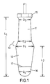
- the booklet for a screwdriver shown in FIG. 1 has two clearly separated handle sections 11, 12, both of which have the shape of a truncated cone. Both handle sections converge from a central area towards the respective handle end. This means that the base surfaces of the truncated cones of the two handle sections 11, 12 face each other.
- the diameter D2 would represent the base of the truncated cone of the blade-side handle portion 11, while the diameter D1 represents the base of the truncated cone of the second handle portion 12.
- This step within which the outer contour 14 of the handle takes a curved course, is, for example, approximately 8 mm long, measured in the longitudinal direction of the handle. Within this level, the transverse dimension of the handle changes almost abruptly from the diameter D2 to the diameter D1.
- the grip section 12 has a larger tip angle, which is, for example, in the range of 12 °. As a result, this grip section 12 converges towards its end more than the blade-side grip section 11.
- a polygonal attachment 15 with an enlarged diameter adjoins the latter.
- the increase in diameter of this polygonal approach 15 relative to the handle portion 11 is required so that this approach 15 when the Screwdriver is placed on a surface, rests on this surface.
- the increase in diameter depends on the length of the blade.
- the step formed between the handle section 11 and the polygonal extension 15 is preferably very short, shorter than is indicated in the drawing. It is not intended to be used as a finger attachment.
- the grip section 12 In the area of its free end, the grip section 12 is strongly rounded beyond its smallest diameter D4, where it is still conical. In an end region 16, which is about a third of the length L2 of the larger handle section 12, the surface of the handle is provided with a fine grain. The boundary of the end section is indicated by line 17 in FIG. 1. In the remaining area between the line 17 and the polygonal extension 15, the surface of both grip sections 12 and the intermediate area 13 is smooth. In this way, the surface and thus the contact friction between the hand and fingers increases, so that a good transmission of the torque is ensured.
- the handle has an exactly circular cross section.
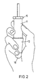
- Fig. 2 shows one way in which the screwdriver handle can be handled according to the invention.
- the thumb, the index finger and, for support, the ring finger rest on the handle.
- the handle section 12 facing away from the blade lies against the inside of the metacarpus, in particular with its end section 16.
- the ring finger and the little finger hold this section 12 firmly.
- the grip section 11 forms the swirl zone, in which the handle is twirled with the first two fingers, possibly with the help of the middle finger. During the twirling, the ring finger and little finger are lifted slightly from the handle, while the end 16 is guided in the metacarpus.
- the screwdriver can be used finger-static, so that all fingers remain on the handle and the short rotary movement can be applied by a small angle from the wrist.
- the screwdriver according to the invention can also be operated, for example, with two hands, in that the left hand guides the blade in left-handers, while the right hand engages in a whirling motion at the end of the larger grip section 12, for example in the area of line 17 of the Fig. 1.
- a high speed can be achieved here when twisting, since the diameter is small there.
- the fingers can attack in the area of the diameter D 1, where, owing to the larger diameter, they achieve a smaller pivoting of the blade and thus greater accuracy.
- the handle is moved finger dynamically. In many screwing operations in particular, it is important for the user of the screwdriver to be able to alternate the way in which he grips the handle. This is not possible with the known power screwdrivers.
- the screwdriver proposed by the invention thus enables fast turning, precise reaching of a certain position and also the briefly required application of a high torque. In addition, it gives the operator the option of changing between several gripping types.
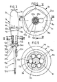
- the booklet 1a is composed of two booklet gripping sections 3a and 4a, which are arranged one behind the other in the axial direction of the blade shaft 2a, in such a way that the two booklet gripping sections 3a, 4a abut one another in a rotary joint 6a with the interposition of a one-way clutch 5a.
- FIG. 3 in particular illustrates that the handle sections 3a, 4a taper without any undercuts, starting from the largest handle cross-section, such that the largest diameter D of the blade-side handle section 4a corresponds approximately to the smallest end diameter d of the head-side handle section 3a.
- the head end 7a of the handle portion 3a has approximately the shape of a hemisphere in order to obtain a good contact surface in the operating hand. Due to the truncated cone form of the handle sections 3a, 4a, it is possible to create the appropriate plastic injection molds without longitudinal division, which facilitates any post-treatment of the molded parts.
- the short step provided between the two handle sections 3a, 4a is provided as a changeover ring 8a for changing the freewheeling direction of the freewheel clutch.
- the truncated cone angle of this tapering step corresponds to approximately 90 ° and is thus many times larger than that of the handle portion 3a, 4a. Accordingly, the switching ring 8a is in a hiding position between the two handle sections. The transition to the handle sections 3a, 4a takes place via corresponding radii 9a, 10a while avoiding annoying projections.
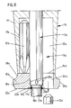
- the blade-side handle portion 4a contains a magazine 11a for receiving screwdriver bits 12a.
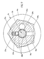
- the magazine 11a has six magazine receiving compartments 13a arranged in the same circumferential distribution and pointing in the axial direction in the form of sack recesses, the mouth openings 14a of which are assigned a turntable 15a on the front side of the handle section 4a.
- the latter is located directly in front of the blade end face 4a 'of the handle portion 4a and rotatably mounted on the blade shaft 2a.
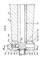
- the turntable 15a is supported by the fact that the blade shaft 2a, which has a hexagonal cross section, merges into a circular-cylindrical section 17a, forming a step 16a.
- the turntable 15a accordingly has a central bearing bore 18a, which is penetrated by the circular cylindrical portion 17a.
- the bearing bore 18a is adjoined by a bearing opening 19a which is larger in cross section. Their diameter is as large as the corner dimension of the Blade shaft 2a.
- the length of the bearing opening 19a corresponds to a multiple of that of the bearing bore 18a.
- the stage 16a gives the turntable 15a a limit stop in the direction of the booklet 1a.
- the removal of the turntable 15a from the section 17a is prevented by a locking ring 20a, which lies in an annular groove 21a of the circular cylindrical section 17a.
- the turntable 15a forms a recess 23a on its lower end face 22a.
- the turntable 15a can be locked in six rotational positions, in which its opening 24a is aligned with one of the magazine receiving compartments 13a.
- a latching ball 26a accommodated in a radial bore 25a of the turntable 15a serves for latching.
- a compression spring 27a loads the detent ball 26a in the inward direction. The latter works together with locking recesses 28a, which are provided in the same cross-sectional plane at the level of the edges of the polygonal blade shaft.
- the turntable 15a is designed so that it has a polygonal outer periphery 29a. This is designed in the form of a pentagon and stands over the cross section the end face 4a 'of the blade-side handle portion 4a. As a transition between the pentagon and the end face 4a 'serves a circumferential ring zone 30a of the turntable 15a, which merges smoothly into the handle portion 4a. This ring zone 30a can also take on a further function by preventing the corresponding fingers of the actuating hand from slipping in the direction of the blade.
- the circular cylindrical section 17a is equipped at its end with a receiving opening (not shown) for inserting a screwdriver bit 12a.
- a screwdriver bit can be removed in the handle.
- the pentagonal shape of the turntable enables easier turning of the turntable by means of the index finger of the grasping hand into a position in which the screwdriver insert to be removed or its magazine receiving compartment is aligned with the opening 24a of the turntable. Then the screwdriver bit 12a slides out and can be brought into the use position. It is not necessary to close the respective magazine storage compartment since there is no screwdriver insert in it.
Landscapes
- Engineering & Computer Science (AREA)
- Mechanical Engineering (AREA)
- Manufacturing & Machinery (AREA)
- Chemical & Material Sciences (AREA)
- Composite Materials (AREA)
- Details Of Spanners, Wrenches, And Screw Drivers And Accessories (AREA)
Applications Claiming Priority (2)
| Application Number | Priority Date | Filing Date | Title |
|---|---|---|---|
| DE3830860 | 1988-09-10 | ||
| DE3830860 | 1988-09-10 |
Publications (3)
| Publication Number | Publication Date |
|---|---|
| EP0359030A2 true EP0359030A2 (fr) | 1990-03-21 |
| EP0359030A3 EP0359030A3 (fr) | 1991-01-16 |
| EP0359030B1 EP0359030B1 (fr) | 1993-12-29 |
Family
ID=6362716
Family Applications (1)
| Application Number | Title | Priority Date | Filing Date |
|---|---|---|---|
| EP89115976A Expired - Lifetime EP0359030B1 (fr) | 1988-09-10 | 1989-08-30 | Tournevis |
Country Status (3)
| Country | Link |
|---|---|
| EP (1) | EP0359030B1 (fr) |
| DE (1) | DE58906551D1 (fr) |
| ES (1) | ES2048248T3 (fr) |
Cited By (2)
| Publication number | Priority date | Publication date | Assignee | Title |
|---|---|---|---|---|
| EP0508849A1 (fr) * | 1991-04-12 | 1992-10-14 | Facom | Manche d'outil, notamment pour tournevis de précision, et outil correspondant |
| WO1998031511A1 (fr) * | 1997-01-17 | 1998-07-23 | Willi Hahn Gmbh & Co. Kg | Systeme d'outils de tournage |
Family Cites Families (10)
| Publication number | Priority date | Publication date | Assignee | Title |
|---|---|---|---|---|
| US2629413A (en) * | 1946-10-17 | 1953-02-24 | Stettler Rudolf | Registering chamber magazine handle |
| GB2017560B (en) * | 1978-02-21 | 1982-10-20 | Personnat Patrice | Combination hand-tool |
| US4290465A (en) * | 1979-10-17 | 1981-09-22 | S/V Tool Company, Inc. | Hand instrument |
| DE3004957A1 (de) * | 1980-02-09 | 1981-08-20 | Fa. W. Holland-Letz, 5608 Radevormwald | Griff fuer einhaddrehwerkzeuge |
| DE3151870A1 (de) * | 1981-12-30 | 1983-07-21 | Felo Holland-Letz GmbH & Co KG, 3577 Neustadt | Werkzeuggriff, insbesondere schraubendrehergriff |
| IT8323144U1 (it) * | 1983-03-10 | 1985-04-04 | Feld Holland Letz Gmbh & Co | Manico di materia artificiale per utensili, in particolare per cacciaviti |
| GB2137545A (en) * | 1983-03-28 | 1984-10-10 | Goo Ton Lin | Screwdriver spanner or socket set |
| DE3400068C2 (de) * | 1984-01-03 | 1986-10-02 | W. Holland-Letz GmbH & Co KG, 5608 Radevormwald | Werkzeug-Handgriff mit Schraubeinsätzen |
| CA1232781A (fr) * | 1984-12-05 | 1988-02-16 | Antonio Corona | Tournevis multilames et mandrin ameliore |
| CA1214953A (fr) * | 1985-08-16 | 1986-12-09 | Archibald M. Mckenzie | Tournevis a jeu de lames et prises interchangeables |
-
1989
- 1989-08-30 DE DE89115976T patent/DE58906551D1/de not_active Expired - Fee Related
- 1989-08-30 EP EP89115976A patent/EP0359030B1/fr not_active Expired - Lifetime
- 1989-08-30 ES ES89115976T patent/ES2048248T3/es not_active Expired - Lifetime
Cited By (3)
| Publication number | Priority date | Publication date | Assignee | Title |
|---|---|---|---|---|
| EP0508849A1 (fr) * | 1991-04-12 | 1992-10-14 | Facom | Manche d'outil, notamment pour tournevis de précision, et outil correspondant |
| FR2675069A1 (fr) * | 1991-04-12 | 1992-10-16 | Facom | Manche d'outil, notamment pour tournevis de precision, et outil correspondant. |
| WO1998031511A1 (fr) * | 1997-01-17 | 1998-07-23 | Willi Hahn Gmbh & Co. Kg | Systeme d'outils de tournage |
Also Published As
| Publication number | Publication date |
|---|---|
| ES2048248T3 (es) | 1994-03-16 |
| DE58906551D1 (de) | 1994-02-10 |
| EP0359030B1 (fr) | 1993-12-29 |
| EP0359030A3 (fr) | 1991-01-16 |
Similar Documents
| Publication | Publication Date | Title |
|---|---|---|
| DE69202384T2 (de) | Ratschenschlüssel. | |
| DE3525163C2 (fr) | ||
| DE2639607A1 (de) | Umstellbares schneidwerkzeug, insbesondere schwenkmesser | |
| WO2001053046A1 (fr) | Poignee d'outil | |
| CH655845A5 (de) | Einrichtung mit einem schraubstift zum einschrauben in einen zahn und einer spannvorrichtung zum halten des schraubstiftes. | |
| DE4328595A1 (de) | Handschraubendreher | |
| DE69503453T2 (de) | Werkzeug zum anziehen von befestigungsmitteln, insbesondere schraubendreher | |
| EP0968793B1 (fr) | Outil variable de vissage et/ou perçage | |
| DE19625416A1 (de) | Anordnung aus einem Schraubendreher und einer entsprechenden Schraube | |
| EP0359030B1 (fr) | Tournevis | |
| DE3531122C2 (fr) | ||
| DE69204883T2 (de) | Werkzeuggriff, insbesondere für Präzisionsschraubendreher, und entsprechende Werkzeuge. | |
| DE8716099U1 (de) | Schraubendreher | |
| DE19511870A1 (de) | Schraubendreher mit ummanteltem Klingenschaft | |
| DE3830859C2 (fr) | ||
| EP0358883A1 (fr) | Tournevis, en particulier tournevis de précision | |
| EP0593906A2 (fr) | Manche de tournevis | |
| DE4429126C2 (de) | Schraubendreher | |
| DE2214466A1 (de) | Aus einem Schraubenzieher und Schraubengreifer bestehendes kombiniertes Werkzeug | |
| DE3808238A1 (de) | Schraubwerkzeug mit drehmomentbegrenzung | |
| DE680192C (de) | Griffhuelse mit mehreren, zweckmaessig drei zur satten Fingerauflage dienenden ebenen Flaechen oder Hohlkehlen, insbesondere fuer zahnaerztliche Handstuecke | |
| EP1072364B1 (fr) | Poignée d'outil | |
| EP0952902B1 (fr) | Systeme d'outils de tournage | |
| EP0413202B1 (fr) | Manche de lime | |
| DE9103170U1 (de) | Reflexhammer |
Legal Events
| Date | Code | Title | Description |
|---|---|---|---|
| PUAI | Public reference made under article 153(3) epc to a published international application that has entered the european phase |
Free format text: ORIGINAL CODE: 0009012 |
|
| AK | Designated contracting states |
Kind code of ref document: A2 Designated state(s): CH DE ES FR GB IT LI SE |
|
| PUAL | Search report despatched |
Free format text: ORIGINAL CODE: 0009013 |
|
| AK | Designated contracting states |
Kind code of ref document: A3 Designated state(s): CH DE ES FR GB IT LI SE |
|
| 17P | Request for examination filed |
Effective date: 19901217 |
|
| 17Q | First examination report despatched |
Effective date: 19920714 |
|
| GRAA | (expected) grant |
Free format text: ORIGINAL CODE: 0009210 |
|
| AK | Designated contracting states |
Kind code of ref document: B1 Designated state(s): CH DE ES FR GB IT LI SE |
|
| ET | Fr: translation filed | ||
| REF | Corresponds to: |
Ref document number: 58906551 Country of ref document: DE Date of ref document: 19940210 |
|
| GBT | Gb: translation of ep patent filed (gb section 77(6)(a)/1977) |
Effective date: 19940114 |
|
| REG | Reference to a national code |
Ref country code: ES Ref legal event code: FG2A Ref document number: 2048248 Country of ref document: ES Kind code of ref document: T3 |
|
| ITF | It: translation for a ep patent filed | ||
| PG25 | Lapsed in a contracting state [announced via postgrant information from national office to epo] |
Ref country code: LI Effective date: 19940831 Ref country code: ES Free format text: LAPSE BECAUSE OF EXPIRATION OF PROTECTION Effective date: 19940831 Ref country code: CH Effective date: 19940831 |
|
| PLBE | No opposition filed within time limit |
Free format text: ORIGINAL CODE: 0009261 |
|
| STAA | Information on the status of an ep patent application or granted ep patent |
Free format text: STATUS: NO OPPOSITION FILED WITHIN TIME LIMIT |
|
| 26N | No opposition filed | ||
| EAL | Se: european patent in force in sweden |
Ref document number: 89115976.6 |
|
| REG | Reference to a national code |
Ref country code: CH Ref legal event code: PL |
|
| PGFP | Annual fee paid to national office [announced via postgrant information from national office to epo] |
Ref country code: SE Payment date: 19950816 Year of fee payment: 7 |
|
| PGFP | Annual fee paid to national office [announced via postgrant information from national office to epo] |
Ref country code: GB Payment date: 19950821 Year of fee payment: 7 |
|
| PGFP | Annual fee paid to national office [announced via postgrant information from national office to epo] |
Ref country code: FR Payment date: 19960723 Year of fee payment: 8 |
|
| PG25 | Lapsed in a contracting state [announced via postgrant information from national office to epo] |
Ref country code: GB Effective date: 19960830 |
|
| PG25 | Lapsed in a contracting state [announced via postgrant information from national office to epo] |
Ref country code: SE Effective date: 19960831 |
|
| GBPC | Gb: european patent ceased through non-payment of renewal fee |
Effective date: 19960830 |
|
| EUG | Se: european patent has lapsed |
Ref document number: 89115976.6 |
|
| PG25 | Lapsed in a contracting state [announced via postgrant information from national office to epo] |
Ref country code: FR Free format text: LAPSE BECAUSE OF NON-PAYMENT OF DUE FEES Effective date: 19980430 |
|
| REG | Reference to a national code |
Ref country code: FR Ref legal event code: ST |
|
| PGFP | Annual fee paid to national office [announced via postgrant information from national office to epo] |
Ref country code: DE Payment date: 19980805 Year of fee payment: 10 |
|
| PG25 | Lapsed in a contracting state [announced via postgrant information from national office to epo] |
Ref country code: DE Free format text: LAPSE BECAUSE OF NON-PAYMENT OF DUE FEES Effective date: 20000601 |
|
| REG | Reference to a national code |
Ref country code: ES Ref legal event code: FD2A Effective date: 20010201 |
|
| PG25 | Lapsed in a contracting state [announced via postgrant information from national office to epo] |
Ref country code: IT Free format text: LAPSE BECAUSE OF NON-PAYMENT OF DUE FEES;WARNING: LAPSES OF ITALIAN PATENTS WITH EFFECTIVE DATE BEFORE 2007 MAY HAVE OCCURRED AT ANY TIME BEFORE 2007. THE CORRECT EFFECTIVE DATE MAY BE DIFFERENT FROM THE ONE RECORDED. Effective date: 20050830 |