EP0359094A1 - Système de transmission pour un signal d'image à haute résolution temporelle et spatiale - Google Patents
Système de transmission pour un signal d'image à haute résolution temporelle et spatiale Download PDFInfo
- Publication number
- EP0359094A1 EP0359094A1 EP89116351A EP89116351A EP0359094A1 EP 0359094 A1 EP0359094 A1 EP 0359094A1 EP 89116351 A EP89116351 A EP 89116351A EP 89116351 A EP89116351 A EP 89116351A EP 0359094 A1 EP0359094 A1 EP 0359094A1
- Authority
- EP
- European Patent Office
- Prior art keywords
- image
- signal
- receiver
- receiver according
- pixel
- Prior art date
- Legal status (The legal status is an assumption and is not a legal conclusion. Google has not performed a legal analysis and makes no representation as to the accuracy of the status listed.)
- Granted
Links
- 230000002123 temporal effect Effects 0.000 title abstract description 9
- 230000005540 biological transmission Effects 0.000 claims description 43
- 230000033001 locomotion Effects 0.000 claims description 23
- 238000011069 regeneration method Methods 0.000 claims description 15
- 230000008929 regeneration Effects 0.000 claims description 14
- 239000013598 vector Substances 0.000 claims description 14
- 238000005070 sampling Methods 0.000 claims description 8
- 238000006243 chemical reaction Methods 0.000 claims description 4
- 230000001419 dependent effect Effects 0.000 claims description 3
- 238000013139 quantization Methods 0.000 claims description 3
- 238000012546 transfer Methods 0.000 claims description 3
- 238000012935 Averaging Methods 0.000 claims description 2
- 230000007547 defect Effects 0.000 claims description 2
- 238000011156 evaluation Methods 0.000 claims description 2
- 230000001629 suppression Effects 0.000 description 5
- 238000001914 filtration Methods 0.000 description 3
- 230000003068 static effect Effects 0.000 description 3
- 238000000034 method Methods 0.000 description 2
- 238000011161 development Methods 0.000 description 1
- 230000018109 developmental process Effects 0.000 description 1
- 238000012545 processing Methods 0.000 description 1
- 230000000750 progressive effect Effects 0.000 description 1
- 230000000717 retained effect Effects 0.000 description 1
- 230000009466 transformation Effects 0.000 description 1
Images


Classifications
-
- H—ELECTRICITY
- H04—ELECTRIC COMMUNICATION TECHNIQUE
- H04N—PICTORIAL COMMUNICATION, e.g. TELEVISION
- H04N7/00—Television systems
- H04N7/12—Systems in which the television signal is transmitted via one channel or a plurality of parallel channels, the bandwidth of each channel being less than the bandwidth of the television signal
-
- H—ELECTRICITY
- H04—ELECTRIC COMMUNICATION TECHNIQUE
- H04N—PICTORIAL COMMUNICATION, e.g. TELEVISION
- H04N19/00—Methods or arrangements for coding, decoding, compressing or decompressing digital video signals
-
- H—ELECTRICITY
- H04—ELECTRIC COMMUNICATION TECHNIQUE
- H04N—PICTORIAL COMMUNICATION, e.g. TELEVISION
- H04N11/00—Colour television systems
- H04N11/24—High-definition television systems
- H04N11/26—High-definition television systems involving two-channel transmission
-
- H—ELECTRICITY
- H04—ELECTRIC COMMUNICATION TECHNIQUE
- H04N—PICTORIAL COMMUNICATION, e.g. TELEVISION
- H04N19/00—Methods or arrangements for coding, decoding, compressing or decompressing digital video signals
- H04N19/50—Methods or arrangements for coding, decoding, compressing or decompressing digital video signals using predictive coding
- H04N19/587—Methods or arrangements for coding, decoding, compressing or decompressing digital video signals using predictive coding involving temporal sub-sampling or interpolation, e.g. decimation or subsequent interpolation of pictures in a video sequence
-
- H—ELECTRICITY
- H04—ELECTRIC COMMUNICATION TECHNIQUE
- H04N—PICTORIAL COMMUNICATION, e.g. TELEVISION
- H04N19/00—Methods or arrangements for coding, decoding, compressing or decompressing digital video signals
- H04N19/50—Methods or arrangements for coding, decoding, compressing or decompressing digital video signals using predictive coding
- H04N19/59—Methods or arrangements for coding, decoding, compressing or decompressing digital video signals using predictive coding involving spatial sub-sampling or interpolation, e.g. alteration of picture size or resolution
-
- H—ELECTRICITY
- H04—ELECTRIC COMMUNICATION TECHNIQUE
- H04N—PICTORIAL COMMUNICATION, e.g. TELEVISION
- H04N7/00—Television systems
- H04N7/12—Systems in which the television signal is transmitted via one channel or a plurality of parallel channels, the bandwidth of each channel being less than the bandwidth of the television signal
- H04N7/122—Systems in which the television signal is transmitted via one channel or a plurality of parallel channels, the bandwidth of each channel being less than the bandwidth of the television signal involving expansion and subsequent compression of a signal segment, e.g. a frame, a line
-
- H—ELECTRICITY
- H04—ELECTRIC COMMUNICATION TECHNIQUE
- H04N—PICTORIAL COMMUNICATION, e.g. TELEVISION
- H04N7/00—Television systems
- H04N7/12—Systems in which the television signal is transmitted via one channel or a plurality of parallel channels, the bandwidth of each channel being less than the bandwidth of the television signal
- H04N7/127—Systems in which different parts of the picture signal frequency band are individually processed, e.g. suppressed, transposed
Definitions
- the invention relates to a transmission and reception system for an image signal.
- HDTV signal a high-resolution television signal
- standard TV signal a standard television signal
- an HDTV signal supplied by a source is split up by means of a digital signal processor by means of two-dimensional local filtering in such a way that the result is a standard TV signal and a signal which supplies the high local frequency components of the HDTV signal.
- These two signals are transmitted separately via two separate band-limited channels, one channel transmitting the standard TV signal and the second channel acting as an additional channel the high local frequency components of the HDTV signal.
- the standard TV signal can then be received on the receiver side by means of a standard TV receiver.
- a suitable HDTV receiver By evaluating the signals of both channels, a suitable HDTV receiver is able to reconstruct and reproduce the image supplied by the source.
- the invention is based on the object of specifying a transmission system and a receiver for a high-resolution television signal which, in the case of existing band-limited transmission channels on the receiver side, enables the reconstruction of image information even when only one channel is received.
- an HDTV signal with high spatial and temporal resolution is split into two signals.
- the first signal has a low local but high temporal resolution and can be encoded in a standard TV signal, e.g. PAL, Secam, NTSC or D2-MAC or digital with or without data reduction, implemented and transmitted over a first band-limited channel.
- a standard TV signal e.g. PAL, Secam, NTSC or D2-MAC or digital with or without data reduction
- the second signal has a high local but low temporal resolution. This can e.g. by omitting images, preferably every other image. With an appropriate coder it can e.g. converted into an HD-MAC signal or transmitted directly digitally with or without data reduction over a second band-limited channel.
- a complete temporally low-resolution and locally high-resolution image signal can be received via the second channel, from which an adequate locally high-resolution image signal, hereinafter referred to as HD signal, can be reconstructed by suitable decoding and measures for image regeneration.
- HD signal an adequate locally high-resolution image signal
- the regeneration measures serve to largely reconstruct the information lost by the receiver by omitting images, particularly in the case of moving sequences.
- both channels must be evaluated on the receiver side.
- the temporally high-resolution image information of the first channel is used in particular in the case of movement defects in the reconstruction of the HD image.
- Information about the corresponding first channel is added to the signal of the second channel.
- this information can be evaluated by the receiver in such a way that it automatically enables the reception of the first channel by means of a corresponding evaluation circuit.
- the transmission system according to the invention thus advantageously results in the introduction of an HDTV transmission system which is compatible with the conventional transmission systems, the first channel providing an image signal with a resolution corresponding to today's television standard and the second channel providing a complete image signal of high local resolution.
- Fig. 1 shows a 2-channel HDTV transmission system.
- An HDTV signal generated by a source becomes a first transmission path, consisting of a transcoder 1, a TV encoder 2, a TV decoder 3 and a transcoder 4, and a second transmission path, consisting of an image suppression circuit 5, an HD encoder 6, an HD decoder 7 and an image regeneration circuit 8.
- the transcoder 1 of the first transmission path reduces the horizontal resolution of the image by 2: 1 and the vertical resolution by 3: 2 by appropriate filtering.
- the HDTV signal present without interlacing is converted into an interlaced signal, with the temporal resolution being retained.
- the output signal of the transcoder 1 is fed to the TV encoder 2, which generates a standard TV signal, for example in PAL, Secam, NTSC or D2-MAC, and whose output is connected to a first transmission channel.
- the output signal of the transcoder is to be stored, for example, on a digital recorder, it is either given directly or via a data reduction device to the first transmission channel, ie the recording channel.
- the incoming standard TV signal is decoded in the TV decoder 3 in the receiver of the first transmission channel.
- the standard TV signal can then be reproduced at the output of the TV decoder 3.
- the HDTV signal which is fed to the second transmission link is subjected to an omission of images in order to adapt to a band-limited second transmission channel.
- the image suppression circuit 5 e.g. only transfer every second picture.
- the output signal of the image suppression circuit 5 reaches a second transmission channel via the HD encoder 6.
- the HD encoder either generates an analog signal, e.g. HD-MAC, or a digital signal that is transmitted over the channel directly or after data reduction.
- the incoming signal is fed to the HD decoder 7 in the receiver of the second transmission channel.
- the output of the HD decoder 7 is connected to the image regeneration circuit 8, which uses a motion estimation to perform a reconstruction of the images omitted on the receiver side by means of block comparison.
- the image regeneration circuit 8 At the output of the image regeneration circuit 8 there is an HD signal with high local resolution and an image repetition frequency of e.g. 50 Hz reproducible, but with possible errors in the area of moving image content.
- the transcoder 4 converts the standard TV signal into an inversion of the sampling rate conversion of the transcoder 1 made. Both signals, that of the transcoder 4 and that of the image regeneration circuit 8, are fed to a combination filter 9 which, by suitable weighting, delivers an HDTV output signal of high temporal and local resolution.
- Fig. 2 describes the transcoder 1 in the transmitter.
- the incoming HDTV signal is fed to a horizontal transcoder filter 9, which lowers the horizontal sampling rate by 2: 1 by suitable filtering.
- a basic process for this is described in Pirsch, P .; Bierling, M .: “Changing the Sampling Rate of Video Signals by Rational Factors", Proc. EUSIPCO '83, Signal Processing II: Theories and Applications, EURASIP 1983, pp. 171-174.
- the signal then passes through a vertical transcoder filter 10, which lowers the vertical sampling rate by 3: 2.
- the output signal then goes through a vertical low-pass filter, followed by an interlacer 11, which performs a field-dependent vertical subsampling of 2: 1 to generate an interlaced image signal.
- Fig. 3 shows the transcoder 4 in the receiver.
- the incoming standard TV signal in the form of digital samples, is fed to a deinterlacer 12 which, by field-dependent line transfer and interpolation of the intermediate lines, converts an image signal in the format 720 * 576, 50 Hz, 2: 1 to an image signal in the format 720 * 576 , 50 Hz, 1: 1 generated.
- the This signal is fed to a vertical transcoder filter 13, which regenerates a signal in the format 720 * 864, 50 Hz, 1: 1 by vertical sampling rate conversion by 2: 3.
- a subsequent horizontal transcoder filter 14 with a horizontal sampling rate conversion of 1: 2 produces a signal with a format comparable to the HDTV input signal with 1440 * 864, 50 Hz, 1: 1.
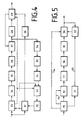
- the HDTV input signal passing through the image suppression circuit 5 is fed to both a mode selection circuit 23 and a block search circuit 31.
- either an interframe or an intraframe mode is selected by comparing the input signal with the output signal of the block search circuit 31 for coding the input signal.
- the coding happens e.g. uniform for a block containing 8 * 8 pixels. Are e.g. the deviations of the current picture from the previous picture are large, then an intra-frame coding is carried out.
- interframe coding is used for data reduction.
- the image signal is predicted along determined motion vectors and the difference signal between the original and prediction signal is forwarded.
- intraframe mode the input signal itself is forwarded.
- the block search circuit 31 determines a motion vector for each current block.
- the motion vector can e.g. B. from the minimum sum of the absolute values of the differences, the minimum sum of the alternating energy or minimal variance.
- the signal is fed to a discrete cosine transformer 24. Its output signal is sorted in a sorter (scanner) 25 and then a weighting circuit 26 and one Quantizer 27 supplied. The output signal of the quantizer 27 is fed to a coder 28 as well as for the reconstruction of the image signal via a circuit for inverse weighting 36, an inverse sampler 35 and an inverse discrete cosine transformer 34 of a block reconstruction circuit 33, the output of which is connected to an image memory 32.
- a sorter scanner
- the output signal of the quantizer 27 is fed to a coder 28 as well as for the reconstruction of the image signal via a circuit for inverse weighting 36, an inverse sampler 35 and an inverse discrete cosine transformer 34 of a block reconstruction circuit 33, the output of which is connected to an image memory 32.
- the encoder 28 receives weighted transformation coefficients quantized as an input signal in a sequence determined by the sampling. For data reduction, it carries out coding with variable word lengths and provides coded coefficients and addresses as an output signal. This is fed to a video multiplexer and buffer memory 29.
- the data stored in the image memory 32 is data from the previous image. They are required to determine movement information for a current block.
- a block of the current picture for example 8 * 8 pixels
- a search area of the previous picture for example 16 * 16 pixels
- a vector is determined from this resulting position and is supplied to the mode selection circuit 23 and a coder 30.
- This coder 30 also carries out coding with variable word length and forwards the coded motion vector for temporary storage in addition to the corresponding signal data to the video multiplexer and buffer memory 29.
- the buffer memory 29 is connected to the quantizer 27.
- the result of the mode selection is fed to the video multiplexer and buffer memory 29 and to the block reconstruction circuit 33 for correct block reconstruction.
- the output signal of the buffer memory 29 is fed to the second transmission channel at a constant data rate.
- Fig. 5 shows the HD decoder 7 with a buffer memory and video demultiplexer 15.
- Each output of the buffer memory 15 leads to a decoder 16 or 21.
- An output of the decoder 16 leads via an inverse weighting 17, an inverse scanner 18 and one inverse discrete cosine transformer 19 to a block reconstruction circuit 20.
- the output of the block reconstruction circuit 20 leads to the image regeneration circuit 8 and to an image or block memory 22.
- the output of the decoder 21 with the decoded motion vectors also leads to a further input of the image or block memory 22.
- the addresses and coefficients are decoded back into their original form.
- the decoder 21 does the same for the motion vectors.
- An information line 54 leads from the buffer memory 15 to the block reconstruction circuit 20 with the information as to whether the block was encoded in the interframe or in the intraframe mode.
- Another line 56 leads from the buffer memory 15 to the decoder 16, which transmit buffer status and information about the quantizer status.
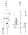
- the output signal of the HD decoder 7 is fed to an image memory 38.
- An output of the image memory 38 leads to an image interpolation circuit 37, a further output to an image memory 39 and a multiplexer 40.
- Further inputs of the image interpolation circuit 37 carry further data from the HD decoder 7, e.g. the motion vectors 53 and the encoder mode information 54, that is information about interframe or intraframe coding.
- An output of the image interpolation circuit 37 leads to the multiplexer 40.
- an HD signal with 1440 * 864 pixels, 50 Hz, 1: 1 can be tapped, hereinafter referred to as HDTV-TV signal.
- FIG. 7 The mode of operation of the image regenerator 8, FIG. 6 is illustrated in FIG. 7 using a one-dimensional example.
- Each image 2n + 1 output by the HD decoder is stored in the image memory 38 of the image regenerator, and the image 2n-1 previously transmitted is held in the image memory 39.
- the intermediate image 2n was omitted from the image suppression circuit 5 on the transmission side.
- Figure 7 shows the signals at the image interpolation circuit 37.
- One input carries the output signal 46 of the image memory 39 with the image information 49 and 50.
- the second input carries the output signal 48 of the image memory 38.
- the output signal 47 with the image information 51 is fed to the multiplexer 40.
- block 51 of the intermediate image 2n is determined directly from image 2n-1 and image 2n + 1 on a block basis by point-by-point averaging of the image contents. This is not shown in Fig. 7.
- the motion vector 53 of block 52 is known from the HD decoder.
- the one around the half motion vector 54 offset block 50 of image 2 n-1 (46) is adopted.
- the image 2n can be generated by pixel-by-pixel interpolation of the images 2n-1 and 2n + 1 shifted in the opposite direction by half the motion vector.
- the temporally high-resolution, locally interpolated and thus corresponding to the format of the HDTV image generated by the transcoder 4 is fed to a summer 41.
- the output signal of the image regeneration circuit 8 is also supplied to the summer 41.
- the summer 41 determines the sum of the absolute gray value differences of the two differently regenerated image signals via a point by point over an n * n window. The sum forms a value Z per window size n * n.
- the weighting factor a can assume a value between 0 and 1.
- the factor a 1 and thus the image information of the TV signal is adopted. If, on the other hand, the value Z is very small, ie if there is static image content, for example, the data is taken from the HD signal, since this represents the original high resolution from the source to the sink.
- the multiplication results of the multipliers are fed to a summer 45, the output signal of which corresponds to the original HDTV signal.
- the image regeneration process is carried out by evaluating both channels on the receiver side.
- the images generated by the above image regeneration methods are combined as follows.
- the differences between the temporally high-resolution, locally interpolated HDTV-TV signal generated by transcoding, which corresponds in format to the HDTV picture, and the HDTV-HD picture generated by picture interpolation are calculated point by point.
- the sum of the absolute gray value differences of the two differently regenerated image signals are determined and weighted point by point via an n * n window.
- a factor a in the range from 0 to 1 is determined by the weighting.
- the HDTV-TV and HDTV-HD image signals are linked with the weighting factor a as follows:
- the HDTV-TV signal is multiplied by the factor a, the HDTV-HD signal by the factor 1-a.
- the factor a 1 and thus the image information of the HDTV-TV signal is adopted. If, on the other hand, the value is very small, e.g. static image content, the data is taken from the HDTV-HD signal, since this represents the original high resolution from the source to the sink.
- the weighting factor a is set to 1 if the weighted sum of the absolute gray values unites Exceed threshold that is less than 1. Up to this threshold, the value of the weighting factor increases proportionally from 0 to 1.
- the weighted addition of the two channels can be determined by evaluated HD decoder information, i.e. Information about the transmission mode, the quantization status or the movement of the block, improve.
Landscapes
- Multimedia (AREA)
- Signal Processing (AREA)
- Engineering & Computer Science (AREA)
- Television Systems (AREA)
- Compression Or Coding Systems Of Tv Signals (AREA)
- Ultra Sonic Daignosis Equipment (AREA)
- Reduction Or Emphasis Of Bandwidth Of Signals (AREA)
- Apparatus For Radiation Diagnosis (AREA)
- Vehicle Body Suspensions (AREA)
- Color Television Systems (AREA)
- Closed-Circuit Television Systems (AREA)
- Two-Way Televisions, Distribution Of Moving Picture Or The Like (AREA)
- Testing, Inspecting, Measuring Of Stereoscopic Televisions And Televisions (AREA)
Applications Claiming Priority (4)
| Application Number | Priority Date | Filing Date | Title |
|---|---|---|---|
| DE3831104A DE3831104A1 (de) | 1988-09-13 | 1988-09-13 | Bildregenerationsverfahren |
| DE3831104 | 1988-09-13 | ||
| DE3831103 | 1988-09-13 | ||
| DE3831103A DE3831103A1 (de) | 1988-09-13 | 1988-09-13 | Uebertragungssystem |
Publications (2)
| Publication Number | Publication Date |
|---|---|
| EP0359094A1 true EP0359094A1 (fr) | 1990-03-21 |
| EP0359094B1 EP0359094B1 (fr) | 1992-12-16 |
Family
ID=25872158
Family Applications (2)
| Application Number | Title | Priority Date | Filing Date |
|---|---|---|---|
| EP89116351A Expired - Lifetime EP0359094B1 (fr) | 1988-09-13 | 1989-09-05 | Système de transmission pour un signal d'image à haute résolution temporelle et spatiale |
| EP89909739A Pending EP0439471A1 (fr) | 1988-09-13 | 1989-09-05 | Systeme de transmission |
Family Applications After (1)
| Application Number | Title | Priority Date | Filing Date |
|---|---|---|---|
| EP89909739A Pending EP0439471A1 (fr) | 1988-09-13 | 1989-09-05 | Systeme de transmission |
Country Status (12)
| Country | Link |
|---|---|
| US (1) | US5055927A (fr) |
| EP (2) | EP0359094B1 (fr) |
| KR (1) | KR900702718A (fr) |
| CN (1) | CN1027483C (fr) |
| AT (1) | ATE83595T1 (fr) |
| AU (1) | AU4191389A (fr) |
| CA (1) | CA1325055C (fr) |
| DE (1) | DE58903019D1 (fr) |
| ES (1) | ES2037358T3 (fr) |
| HK (1) | HK78594A (fr) |
| SG (2) | SG36672G (fr) |
| WO (1) | WO1990003082A1 (fr) |
Cited By (3)
| Publication number | Priority date | Publication date | Assignee | Title |
|---|---|---|---|---|
| WO1991007847A1 (fr) * | 1989-11-14 | 1991-05-30 | Deutsche Thomson-Brandt Gmbh | Dispositif de transmission |
| EP0477632A3 (en) * | 1990-09-14 | 1993-03-31 | Interessengemeinschaft Fuer Rundfunkschutzrechte Gmbh Schutzrechtsverwertung & Co. Kg. | Method for the bandsplitting of a signal being sampled with a fundamental sampling frequency in a transmitter and for bringing the bands together in a receiver |
| SG94685A1 (en) * | 1993-10-18 | 2003-03-18 | Canon Kk | Image data processing and encrypting apparatus |
Families Citing this family (40)
| Publication number | Priority date | Publication date | Assignee | Title |
|---|---|---|---|---|
| US6563875B2 (en) * | 1987-12-30 | 2003-05-13 | Thomson Licensing S.A. | Adaptive method of encoding and decoding a series of pictures by transformation, and devices for implementing this method |
| IT1230235B (it) * | 1989-06-07 | 1991-10-18 | Telettra Spa | Strutturazione e trasmissione a pacchetti dell'informazione generata da codificatore per segnali video. |
| FR2660139B1 (fr) * | 1990-03-23 | 1995-08-25 | France Etat | Procede de codage et de transmission a au moins deux niveaux de qualite d'images numeriques appartenant a une sequence d'images, et dispositifs correspondants. |
| US5528299A (en) * | 1990-10-09 | 1996-06-18 | U.S. Philips Corporation | Coding system for digital signals corresponding to television pictures and corresponding decoding system |
| US5367334A (en) * | 1991-05-20 | 1994-11-22 | Matsushita Electric Industrial Co., Ltd. | Video signal encoding and decoding apparatus |
| NL9101080A (nl) * | 1991-06-24 | 1993-01-18 | Koninkl Philips Electronics Nv | Inrichting voor het splitsen van een digitaal geinterlinieerd televisie signaal in componenten. |
| US5144425A (en) * | 1991-08-26 | 1992-09-01 | General Electric Company | Apparatus for hierarchically dividing video signals |
| US5231384A (en) * | 1991-08-26 | 1993-07-27 | General Electric Company | Apparatus for splitting video signal between two channels |
| GB2259421B (en) * | 1991-09-04 | 1995-01-18 | Sony Broadcast & Communication | Image data recording and transmission |
| KR100283343B1 (ko) * | 1992-06-25 | 2001-03-02 | 이데이 노부유끼 | 화상신호 부호화방법 및 복호화방법과 화상신호 부호화장치 및 복호화장치 |
| US5231486A (en) * | 1992-07-27 | 1993-07-27 | General Electric Company | Data separation processing in a dual channel digital high definition television system |
| GB9219185D0 (en) * | 1992-09-10 | 1992-10-28 | Thomson Consumer Electronics | A single digital modem encoder to generate a twin qam signal for advanced digital television (adtv) |
| US5477397A (en) * | 1993-02-23 | 1995-12-19 | Matsushita Electric Corporation Of America | Digital high definition television receiver with features that facilitate trick-play modes on a digital VCR |
| CA2115976C (fr) * | 1993-02-23 | 2002-08-06 | Saiprasad V. Naimpally | Magnetoscope de television haute definition numerique a fonctions speciales |
| US5410355A (en) * | 1993-04-02 | 1995-04-25 | Rca Thomson Licensing Corporation | Video signal processor including input codeword buffer for providing stored codewords to codeword priority analysis circuit |
| US5412426A (en) * | 1993-04-16 | 1995-05-02 | Harris Corporation | Multiplexing of digitally encoded NTSC and HDTV signals over single microwave communication link from television studio to tower transmitter facility for simultaneous broadcast (simulcast) to customer sites by transmitter facility |
| JP2979900B2 (ja) * | 1993-05-26 | 1999-11-15 | 日本ビクター株式会社 | 記録媒体 |
| US5408270A (en) * | 1993-06-24 | 1995-04-18 | Massachusetts Institute Of Technology | Advanced television system |
| CA2126467A1 (fr) * | 1993-07-13 | 1995-01-14 | Barin Geoffry Haskell | Codage et decodage variables pour systeme video haute definition progressif |
| BE1007330A3 (nl) * | 1993-07-16 | 1995-05-16 | Philips Electronics Nv | Inrichting voor het overdragen van een digitaal beeldsignaal. |
| US6870886B2 (en) * | 1993-12-15 | 2005-03-22 | Koninklijke Philips Electronics N.V. | Method and apparatus for transcoding a digitally compressed high definition television bitstream to a standard definition television bitstream |
| US6243139B1 (en) * | 1993-12-22 | 2001-06-05 | Canon Kabushiki Kaisha | Apparatus for block-encoding input image signals |
| JP3332580B2 (ja) * | 1994-06-14 | 2002-10-07 | キヤノン株式会社 | 画像再生装置及び画像再生方式 |
| US5572248A (en) * | 1994-09-19 | 1996-11-05 | Teleport Corporation | Teleconferencing method and system for providing face-to-face, non-animated teleconference environment |
| US5771073A (en) * | 1995-06-07 | 1998-06-23 | Massachusetts Institute Of Technology | Advanced television system using a different encoding technique for non-image areas |
| WO1999022518A1 (fr) * | 1997-10-28 | 1999-05-06 | Siemens Aktiengesellschaft | Procede et dispositif pour le traitement d'une image numerique |
| EP1247401B1 (fr) * | 1999-12-30 | 2003-07-02 | Swisscom Mobile AG | Procede de transmission de donnees-image |
| GB0002481D0 (en) * | 2000-02-04 | 2000-03-22 | Eastman Kodak Co | Method of image processing |
| US6680752B1 (en) * | 2000-03-31 | 2004-01-20 | Ati International Srl | Method and apparatus for deinterlacing video |
| JP2004503960A (ja) * | 2000-06-15 | 2004-02-05 | コーニンクレッカ フィリップス エレクトロニクス エヌ ヴィ | 画像シーケンスのノイズフィルタリング |
| GB2400254A (en) * | 2003-03-31 | 2004-10-06 | Sony Uk Ltd | Video processing |
| US20060245737A1 (en) * | 2005-04-29 | 2006-11-02 | Walker Philip M | Combining different content discs for playback of supplemental content |
| US20060271990A1 (en) * | 2005-05-18 | 2006-11-30 | Rodriguez Arturo A | Higher picture rate HD encoding and transmission with legacy HD backward compatibility |
| US8457214B2 (en) | 2007-09-10 | 2013-06-04 | Cisco Technology, Inc. | Video compositing of an arbitrary number of source streams using flexible macroblock ordering |
| US8300987B2 (en) * | 2007-09-28 | 2012-10-30 | Ati Technologies Ulc | Apparatus and method for generating a detail-enhanced upscaled image |
| US8964117B2 (en) | 2007-09-28 | 2015-02-24 | Ati Technologies Ulc | Single-pass motion adaptive deinterlacer and method therefore |
| US8259228B2 (en) * | 2007-12-10 | 2012-09-04 | Ati Technologies Ulc | Method and apparatus for high quality video motion adaptive edge-directional deinterlacing |
| US8396129B2 (en) * | 2007-12-28 | 2013-03-12 | Ati Technologies Ulc | Apparatus and method for single-pass, gradient-based motion compensated image rate conversion |
| US10567703B2 (en) | 2017-06-05 | 2020-02-18 | Cisco Technology, Inc. | High frame rate video compatible with existing receivers and amenable to video decoder implementation |
| US10572976B2 (en) * | 2017-10-18 | 2020-02-25 | International Business Machines Corporation | Enhancing observation resolution using continuous learning |
Citations (3)
| Publication number | Priority date | Publication date | Assignee | Title |
|---|---|---|---|---|
| EP0113933A1 (fr) * | 1982-12-22 | 1984-07-25 | Philips Electronics Uk Limited | Système de transmission de télévision |
| WO1987005769A1 (fr) * | 1986-03-19 | 1987-09-24 | British Broadcasting Corporation | Mesurage du mouvement d'images tv |
| DE3704777C1 (de) * | 1987-02-16 | 1988-04-07 | Ant Nachrichtentech | Verfahren zum UEbertragen und zum Wiedergeben von Fernsehbildsequenzen |
Family Cites Families (10)
| Publication number | Priority date | Publication date | Assignee | Title |
|---|---|---|---|---|
| DE2920303C2 (de) * | 1979-05-19 | 1984-02-16 | Robert Bosch Gmbh, 7000 Stuttgart | Vorrichtung zum Übertragen von Videosignalen |
| US4383272A (en) * | 1981-04-13 | 1983-05-10 | Bell Telephone Laboratories, Incorporated | Video signal interpolation using motion estimation |
| JPS58197983A (ja) * | 1982-05-14 | 1983-11-17 | Nec Corp | 動き補償フレ−ム間復号化装置 |
| US4628344A (en) * | 1982-09-14 | 1986-12-09 | New York Institute Of Technoloy | Method and apparatus for encoding and decoding video |
| GB2132846A (en) * | 1982-12-22 | 1984-07-11 | Philips Electronic Associated | Television transmission system |
| NL8301071A (nl) * | 1983-03-28 | 1984-10-16 | Philips Nv | Televisiestelsel met een lijnenaantalconversie en daartoe geschikte informatiegever en -ontvanger. |
| JPH0644815B2 (ja) * | 1984-04-27 | 1994-06-08 | 日本電気株式会社 | 動物体の動き内挿装置 |
| IT1215909B (it) * | 1988-02-18 | 1990-02-22 | Rai Radiotelevisione Italiana | Procedimento di generazione e trasmissione di segnali televisivi a colori ad alta definizione compatibile con gli standardattuali e procedimento e apparecchiatura di ricezione didetti segnali. |
| US4907069A (en) * | 1988-06-01 | 1990-03-06 | Zenith Electronics Corporation | Two-channel compatible HDTV system |
| EP0368400B1 (fr) * | 1988-11-08 | 1995-05-10 | Laboratoires D'electronique Philips | Codage, décodage et système de transmission d'images de télévision |
-
1989
- 1989-09-05 US US07/402,701 patent/US5055927A/en not_active Expired - Lifetime
- 1989-09-05 AU AU41913/89A patent/AU4191389A/en not_active Abandoned
- 1989-09-05 SG SG1995904884A patent/SG36672G/en unknown
- 1989-09-05 AT AT89116351T patent/ATE83595T1/de not_active IP Right Cessation
- 1989-09-05 EP EP89116351A patent/EP0359094B1/fr not_active Expired - Lifetime
- 1989-09-05 WO PCT/EP1989/001035 patent/WO1990003082A1/fr not_active Ceased
- 1989-09-05 EP EP89909739A patent/EP0439471A1/fr active Pending
- 1989-09-05 ES ES198989116351T patent/ES2037358T3/es not_active Expired - Lifetime
- 1989-09-05 DE DE8989116351T patent/DE58903019D1/de not_active Expired - Fee Related
- 1989-09-11 CN CN89107062A patent/CN1027483C/zh not_active Expired - Fee Related
- 1989-09-13 CA CA000611169A patent/CA1325055C/fr not_active Expired - Fee Related
-
1990
- 1990-05-14 KR KR1019900701006A patent/KR900702718A/ko not_active Withdrawn
-
1993
- 1993-05-20 SG SG66493A patent/SG66493G/en unknown
-
1994
- 1994-08-04 HK HK78594A patent/HK78594A/xx not_active IP Right Cessation
Patent Citations (3)
| Publication number | Priority date | Publication date | Assignee | Title |
|---|---|---|---|---|
| EP0113933A1 (fr) * | 1982-12-22 | 1984-07-25 | Philips Electronics Uk Limited | Système de transmission de télévision |
| WO1987005769A1 (fr) * | 1986-03-19 | 1987-09-24 | British Broadcasting Corporation | Mesurage du mouvement d'images tv |
| DE3704777C1 (de) * | 1987-02-16 | 1988-04-07 | Ant Nachrichtentech | Verfahren zum UEbertragen und zum Wiedergeben von Fernsehbildsequenzen |
Non-Patent Citations (4)
| Title |
|---|
| I.E.E.E. TRANSACTIONS ON BROADCASTING, Band BC-33, Nr. 4, Dezember 1987, Seiten 107-115, IEEE, New York, NY, US; W.E. GLENN et al.: "High definition television compatible transmission system" * |
| I.E.E.E. TRANSACTIONS ON CIRCUITS AND SYSTEMS, Band CAS-34, Nr. 11, November 1987, Seiten 1432-1439, IEEE, New York, NY, US; G. SCHAMEL: "Pre- and postfiltering of HDTV signals for sampling rate reduction and display up-conversion" * |
| I.E.E.E. TRANSACTIONS ON CONSUMER ELECTRONICS "1988 INTERNATIONAL CONFERENCE ON CONSUMER ELECTRONICS, PART 1", Band 34, Nr. 3, August 1988, Seiten 484-492, IEEE, New York, NY, US; W.E. BRETL: "3XNTSC-A "Leapfrog" production standard for HDTV" * |
| PHILIPS TECHNICAL REVIEW, Band 43, Nr. 8, August 1987, Seiten 197-212, Eindhoven, NL; M.J.J.C. ANNEGARN et al.: "HD-MAC: a step forward in the evolution of television technology" * |
Cited By (3)
| Publication number | Priority date | Publication date | Assignee | Title |
|---|---|---|---|---|
| WO1991007847A1 (fr) * | 1989-11-14 | 1991-05-30 | Deutsche Thomson-Brandt Gmbh | Dispositif de transmission |
| EP0477632A3 (en) * | 1990-09-14 | 1993-03-31 | Interessengemeinschaft Fuer Rundfunkschutzrechte Gmbh Schutzrechtsverwertung & Co. Kg. | Method for the bandsplitting of a signal being sampled with a fundamental sampling frequency in a transmitter and for bringing the bands together in a receiver |
| SG94685A1 (en) * | 1993-10-18 | 2003-03-18 | Canon Kk | Image data processing and encrypting apparatus |
Also Published As
| Publication number | Publication date |
|---|---|
| AU4191389A (en) | 1990-04-02 |
| ES2037358T3 (es) | 1993-06-16 |
| HK78594A (en) | 1994-08-12 |
| SG66493G (en) | 1993-08-06 |
| US5055927A (en) | 1991-10-08 |
| WO1990003082A1 (fr) | 1990-03-22 |
| CA1325055C (fr) | 1993-12-07 |
| CN1027483C (zh) | 1995-01-18 |
| EP0439471A1 (fr) | 1991-08-07 |
| EP0359094B1 (fr) | 1992-12-16 |
| CN1041254A (zh) | 1990-04-11 |
| ATE83595T1 (de) | 1993-01-15 |
| DE58903019D1 (de) | 1993-01-28 |
| SG36672G (en) | 1995-09-18 |
| KR900702718A (ko) | 1990-12-08 |
Similar Documents
| Publication | Publication Date | Title |
|---|---|---|
| EP0359094B1 (fr) | Système de transmission pour un signal d'image à haute résolution temporelle et spatiale | |
| DE69323586T2 (de) | Gerät zur Schichtkodierung/-dekodierung für ein progressives Eingangsbildsignal | |
| DE69120139T2 (de) | Gerät und Verfahren zur adaptiven Kompression von aufeinanderfolgenden Blöcken eines digitalen Videosignals | |
| DE69131438T2 (de) | Adaptive Bewegungskompensation für das digitale Fernsehen | |
| DE69130329T2 (de) | System und verfahren zur codierung eines zeilensprunghalbbildes | |
| DE69221191T2 (de) | Verfahren und Vorrichtung zur Prädiktiven Kodierung eines Bildsignals mit Bewegungskompensation | |
| DE69233505T2 (de) | Videokodierungssystem | |
| DE69535228T2 (de) | Bildumsetzungsvorrichtung | |
| DE69118654T2 (de) | Progressives Signalkodierungssystem für bewegte Bilder | |
| DE69322769T2 (de) | Koder für zeitveränderliche bilder | |
| DE69232063T2 (de) | Adaptive Bewegungskompensation mit mehreren Bewegungskompensatoren | |
| DE69423798T2 (de) | Vorrichtungungen und Verfahren zur skalierbaren Kodierung und Dekodierung von Videosignalen | |
| DE69031045T2 (de) | Einrichtung zur adaptiven Zwischenbild-Prädiktionsdekodierung eines Videosignals | |
| DE69417480T2 (de) | Bestimmung von Bewegungsvektoren in einem Videokodierer mit Bilddezimation | |
| DE69422564T2 (de) | Verfahren zur halbpixel Bewegungskompensation in Bilddekodierung | |
| DE69415158T2 (de) | Verfahren und vorrichtung zur skalierbaren bildsignalkomprimierung | |
| DE60214837T2 (de) | Erkennung und genaue skalierung bewegter bereiche mit zeilensprung in mpeg-2 komprimiertem video | |
| DE69510753T2 (de) | Vorrichtung zum Interpolieren von Abtastzeilen und Bewegungsvektordetektor | |
| DE69836470T2 (de) | Überträger, empfänger und medium für progressives bildsignal | |
| DE68918893T2 (de) | Verfahren und Installation zur Sendung von kompatiblen Hochauflösungsfernsehprogrammen. | |
| DE69229255T2 (de) | Kodierungs- und Dekodierungseinrichtung für ein Videosignal | |
| DE69322816T2 (de) | Vorrichtung zur Kodierung von digitalen Bildsignalen mit Bewegungskompensation | |
| EP0346637B1 (fr) | Procédé pour le traitement et la transmission d'une séquence d'images | |
| DE69709293T2 (de) | Verfahren und Vorrichtung zur Kodierung und Dekodierung von Bewegtbildern | |
| EP0533675B1 (fr) | Dispositif de transmission |
Legal Events
| Date | Code | Title | Description |
|---|---|---|---|
| PUAI | Public reference made under article 153(3) epc to a published international application that has entered the european phase |
Free format text: ORIGINAL CODE: 0009012 |
|
| AK | Designated contracting states |
Kind code of ref document: A1 Designated state(s): ES GR |
|
| 17P | Request for examination filed |
Effective date: 19900822 |
|
| XX | Miscellaneous (additional remarks) |
Free format text: VERBUNDEN MIT 89909739.8/0439471 (EUROPAEISCHE ANMELDENUMMER/VEROEFFENTLICHUNGSNUMMER) DURCH ENTSCHEIDUNG VOM 14.08.91. |
|
| 17Q | First examination report despatched |
Effective date: 19911009 |
|
| GRAA | (expected) grant |
Free format text: ORIGINAL CODE: 0009210 |
|
| ITF | It: translation for a ep patent filed | ||
| AK | Designated contracting states |
Kind code of ref document: B1 Designated state(s): AT BE CH DE ES FR GB GR IT LI LU NL SE |
|
| PG25 | Lapsed in a contracting state [announced via postgrant information from national office to epo] |
Ref country code: GR Free format text: LAPSE BECAUSE OF FAILURE TO SUBMIT A TRANSLATION OF THE DESCRIPTION OR TO PAY THE FEE WITHIN THE PRESCRIBED TIME-LIMIT Effective date: 19921216 |
|
| REF | Corresponds to: |
Ref document number: 83595 Country of ref document: AT Date of ref document: 19930115 Kind code of ref document: T |
|
| XX | Miscellaneous (additional remarks) |
Free format text: VERBUNDEN MIT 89909739.8/0439471 (EUROPAEISCHE ANMELDENUMMER/VEROEFFENTLICHUNGSNUMMER) DURCH ENTSCHEIDUNG VOM 14.08.91. |
|
| GBT | Gb: translation of ep patent filed (gb section 77(6)(a)/1977) |
Effective date: 19921216 |
|
| REF | Corresponds to: |
Ref document number: 58903019 Country of ref document: DE Date of ref document: 19930128 |
|
| ET | Fr: translation filed | ||
| REG | Reference to a national code |
Ref country code: ES Ref legal event code: FG2A Ref document number: 2037358 Country of ref document: ES Kind code of ref document: T3 |
|
| PLBE | No opposition filed within time limit |
Free format text: ORIGINAL CODE: 0009261 |
|
| STAA | Information on the status of an ep patent application or granted ep patent |
Free format text: STATUS: NO OPPOSITION FILED WITHIN TIME LIMIT |
|
| 26N | No opposition filed | ||
| EPTA | Lu: last paid annual fee | ||
| EAL | Se: european patent in force in sweden |
Ref document number: 89116351.1 |
|
| REG | Reference to a national code |
Ref country code: GB Ref legal event code: 746 Effective date: 19970904 |
|
| REG | Reference to a national code |
Ref country code: GB Ref legal event code: IF02 |
|
| PGFP | Annual fee paid to national office [announced via postgrant information from national office to epo] |
Ref country code: GB Payment date: 20060728 Year of fee payment: 18 |
|
| PGFP | Annual fee paid to national office [announced via postgrant information from national office to epo] |
Ref country code: FR Payment date: 20060914 Year of fee payment: 18 |
|
| PGFP | Annual fee paid to national office [announced via postgrant information from national office to epo] |
Ref country code: DE Payment date: 20060918 Year of fee payment: 18 Ref country code: NL Payment date: 20060918 Year of fee payment: 18 |
|
| PGFP | Annual fee paid to national office [announced via postgrant information from national office to epo] |
Ref country code: BE Payment date: 20060922 Year of fee payment: 18 Ref country code: AT Payment date: 20060922 Year of fee payment: 18 |
|
| PGFP | Annual fee paid to national office [announced via postgrant information from national office to epo] |
Ref country code: CH Payment date: 20060925 Year of fee payment: 18 |
|
| PGFP | Annual fee paid to national office [announced via postgrant information from national office to epo] |
Ref country code: ES Payment date: 20060926 Year of fee payment: 18 |
|
| PGFP | Annual fee paid to national office [announced via postgrant information from national office to epo] |
Ref country code: LU Payment date: 20060927 Year of fee payment: 18 |
|
| PGFP | Annual fee paid to national office [announced via postgrant information from national office to epo] |
Ref country code: IT Payment date: 20060930 Year of fee payment: 18 |
|
| PGFP | Annual fee paid to national office [announced via postgrant information from national office to epo] |
Ref country code: SE Payment date: 20060925 Year of fee payment: 18 |
|
| BERE | Be: lapsed |
Owner name: DEUTSCHE *THOMSON-BRANDT G.M.B.H. Effective date: 20070930 |
|
| PG25 | Lapsed in a contracting state [announced via postgrant information from national office to epo] |
Ref country code: SE Free format text: LAPSE BECAUSE OF NON-PAYMENT OF DUE FEES Effective date: 20070906 |
|
| REG | Reference to a national code |
Ref country code: CH Ref legal event code: PL |
|
| EUG | Se: european patent has lapsed | ||
| GBPC | Gb: european patent ceased through non-payment of renewal fee |
Effective date: 20070905 |
|
| PG25 | Lapsed in a contracting state [announced via postgrant information from national office to epo] |
Ref country code: NL Free format text: LAPSE BECAUSE OF NON-PAYMENT OF DUE FEES Effective date: 20080401 |
|
| NLV4 | Nl: lapsed or anulled due to non-payment of the annual fee |
Effective date: 20080401 |
|
| PG25 | Lapsed in a contracting state [announced via postgrant information from national office to epo] |
Ref country code: AT Free format text: LAPSE BECAUSE OF NON-PAYMENT OF DUE FEES Effective date: 20070905 |
|
| PG25 | Lapsed in a contracting state [announced via postgrant information from national office to epo] |
Ref country code: LI Free format text: LAPSE BECAUSE OF NON-PAYMENT OF DUE FEES Effective date: 20070930 Ref country code: DE Free format text: LAPSE BECAUSE OF NON-PAYMENT OF DUE FEES Effective date: 20080401 Ref country code: CH Free format text: LAPSE BECAUSE OF NON-PAYMENT OF DUE FEES Effective date: 20070930 |
|
| PG25 | Lapsed in a contracting state [announced via postgrant information from national office to epo] |
Ref country code: BE Free format text: LAPSE BECAUSE OF NON-PAYMENT OF DUE FEES Effective date: 20070930 |
|
| REG | Reference to a national code |
Ref country code: FR Ref legal event code: ST Effective date: 20080531 |
|
| PG25 | Lapsed in a contracting state [announced via postgrant information from national office to epo] |
Ref country code: FR Free format text: LAPSE BECAUSE OF NON-PAYMENT OF DUE FEES Effective date: 20071001 |
|
| PG25 | Lapsed in a contracting state [announced via postgrant information from national office to epo] |
Ref country code: GB Free format text: LAPSE BECAUSE OF NON-PAYMENT OF DUE FEES Effective date: 20070905 |
|
| REG | Reference to a national code |
Ref country code: ES Ref legal event code: FD2A Effective date: 20070906 |
|
| PG25 | Lapsed in a contracting state [announced via postgrant information from national office to epo] |
Ref country code: ES Free format text: LAPSE BECAUSE OF NON-PAYMENT OF DUE FEES Effective date: 20070906 |
|
| PG25 | Lapsed in a contracting state [announced via postgrant information from national office to epo] |
Ref country code: IT Free format text: LAPSE BECAUSE OF NON-PAYMENT OF DUE FEES Effective date: 20070905 Ref country code: LU Free format text: LAPSE BECAUSE OF NON-PAYMENT OF DUE FEES Effective date: 20070905 |