EP0359162A2 - Installation de halage pour roue de véhicule dans une installation de lavage de voiture - Google Patents
Installation de halage pour roue de véhicule dans une installation de lavage de voiture Download PDFInfo
- Publication number
- EP0359162A2 EP0359162A2 EP89116732A EP89116732A EP0359162A2 EP 0359162 A2 EP0359162 A2 EP 0359162A2 EP 89116732 A EP89116732 A EP 89116732A EP 89116732 A EP89116732 A EP 89116732A EP 0359162 A2 EP0359162 A2 EP 0359162A2
- Authority
- EP
- European Patent Office
- Prior art keywords
- sliding blocks
- towing
- towing device
- traction means
- traction
- Prior art date
- Legal status (The legal status is an assumption and is not a legal conclusion. Google has not performed a legal analysis and makes no representation as to the accuracy of the status listed.)
- Ceased
Links
- 238000005406 washing Methods 0.000 title description 3
- 238000009434 installation Methods 0.000 title 1
- 229910000831 Steel Inorganic materials 0.000 description 2
- 229910052782 aluminium Inorganic materials 0.000 description 2
- XAGFODPZIPBFFR-UHFFFAOYSA-N aluminium Chemical compound [Al] XAGFODPZIPBFFR-UHFFFAOYSA-N 0.000 description 2
- 238000005452 bending Methods 0.000 description 2
- 238000010276 construction Methods 0.000 description 2
- 230000001846 repelling effect Effects 0.000 description 2
- 238000005096 rolling process Methods 0.000 description 2
- 239000010959 steel Substances 0.000 description 2
- 239000000969 carrier Substances 0.000 description 1
- 238000012423 maintenance Methods 0.000 description 1
- 229910052751 metal Inorganic materials 0.000 description 1
- 239000002184 metal Substances 0.000 description 1
- 230000004048 modification Effects 0.000 description 1
- 238000012986 modification Methods 0.000 description 1
- 238000005494 tarnishing Methods 0.000 description 1
Images

Classifications
-
- B—PERFORMING OPERATIONS; TRANSPORTING
- B60—VEHICLES IN GENERAL
- B60S—SERVICING, CLEANING, REPAIRING, SUPPORTING, LIFTING, OR MANOEUVRING OF VEHICLES, NOT OTHERWISE PROVIDED FOR
- B60S3/00—Vehicle cleaning apparatus not integral with vehicles
- B60S3/004—Conveyors for vehicle cleaning apparatus
-
- B—PERFORMING OPERATIONS; TRANSPORTING
- B65—CONVEYING; PACKING; STORING; HANDLING THIN OR FILAMENTARY MATERIAL
- B65G—TRANSPORT OR STORAGE DEVICES, e.g. CONVEYORS FOR LOADING OR TIPPING, SHOP CONVEYOR SYSTEMS OR PNEUMATIC TUBE CONVEYORS
- B65G19/00—Conveyors comprising an impeller or a series of impellers carried by an endless traction element and arranged to move articles or materials over a supporting surface or underlying material, e.g. endless scraper conveyors
- B65G19/02—Conveyors comprising an impeller or a series of impellers carried by an endless traction element and arranged to move articles or materials over a supporting surface or underlying material, e.g. endless scraper conveyors for articles, e.g. for containers
Definitions
- the invention relates to a towing device with the features in the preamble of the main claim.
- GB 529 157 shows a towing device with a moving grating, between the crossbars of which the vehicle wheel rests. From DE-OS 20 17 089 is also the arrangement of a Deflector known before the drag roller.
- the invention solves this problem with the features in the characterizing part of the main claim.
- the sliding blocks take over the lateral guidance during transport.
- the vehicle wheel still pushed by the towing roller can no longer ride on the moving sliding block and leave the towing track.
- the sliding blocks prevent damage to the wheel parts protruding to the side, in particular to modern aluminum rims.
- Even vehicles with over-wide tires that do not fit in the towing track are no longer a problem for the towing device according to the invention. Such wide tires can be gripped and charged by the sliding blocks without damage.
- the sliding blocks can be arranged on or above the traction means. However, they are preferably arranged as a separate component next to the traction means and are independently supported on the floor. Here, storage and independent guidance on a rail are ideal. This has particular advantages in terms of wear.
- the wheel forces are supported on a component that is easy to change and not on the traction mechanism itself.
- the vehicle wheel can move freely between the successive sliding blocks and without contact with moving parts of the towing device Tread can be positioned. This is particularly advantageous for extra-wide tires that have enough space to position between the further apart traction element strands and are only charged by the next approaching sliding block. This results in high operational and accident safety. If the sliding blocks are higher than the neighboring traction device or its cover, the tires can be of any width and even protrude laterally over the traction device.
- a beveling of the sliding blocks has the advantage that an undesired riding of the wheel is avoided in all situations with certainty. It also serves to improve the protection of the wheel and especially the rims. If the bevel is present on both opposite sliding blocks, a funnel guide is created, which also allows the safe mounting and guiding of wide tires, which do not yet protrude over the sliding blocks on either side, but which also have no place in the track.
- the bevel can not only be used for sliding blocks which are arranged separately from the traction means, but can also be used successfully for any guide elements carried with the traction means. These can be, for example, support elements placed directly on a chain or a traction device designed directly in the form of sliding blocks. This would be an appropriately designed chain link, for example.
- the first link of the sliding blocks can have an inwardly directed guide surface.
- the towing device according to the invention can consist of a traction device with only one strand and trailing rollers and sliding blocks arranged thereon at intervals. In the preferred embodiment, however, two strands are provided, on which the sliding blocks are fastened at the same height on both sides of the track.
- the sliding blocks and the drag roller can be connected to the traction means separately from one another. For reasons of construction costs and stability, however, it is advisable to connect the parts to one another to form a U-shaped drag shoe, the drag roller being mounted on the sliding blocks.
- the connection to the traction device is preferably made at the front end via a rotatably mounted bolt.
- the sliding blocks are not only in front of but also behind the drag roller. This can be achieved with all types of sliding blocks.
- An H-shaped drag shoe is created in the combination of the sliding blocks and the drag roller.
- the rear sliding block area primarily allows the front wheels to be guided, should the rear wheels be dragged by a roller jump and the front wheels run free. In this case, the chamfering of the sliding blocks with their improved repelling function is particularly advantageous.
- the rear sliding block area has a certain distance from the next rear drag roller, which is coordinated with the usual or even the smallest wheelbase. Accordingly, there are certain lengths of the rear sliding block area. If the latter is chosen to be relatively large, small cars with a short wheelbase can experience lateral guidance through the sliding blocks on all wheels even when the front wheels are towed.
- the towing device according to the invention can be operated with traction means of any kind, for example chains, belts, ropes or the like.
- the invention also allows the sliding blocks, preferably in the form of the U-shaped drag shoes, to be releasably attached to the traction means.
- a rope is particularly suitable for this purpose, which is in towing engagement with the sliding blocks via drivers.
- the traction device can thus run around continuously, while the sliding blocks are only hung up and taken along when necessary. On the one hand, this reduces the wear of the moving parts and, on the other hand, improves the accident safety for persons who enter the towing track during maintenance work, when leaving the vehicle or the like on other occasions.
- the sliding blocks consist of a plurality of links which are connected to one another in an articulated manner and can thus follow the curvatures of the traction means at the deflection points.
- the sliding blocks can alternatively consist of a number of separate links that are individually connected to the traction mechanism.
- This construction is simple and particularly reliable in terms of wear.
- the link length corresponds to the pitch of the chain or the corresponding size of a traction device of any other design.
- the arrangement of separate links is suitable for all types of sliding blocks.
- connection points are freely accessible without dismantling the chain.
- the sliding blocks are guided in the longitudinal direction on a rail and are preferably also supported on this.
- lateral guidance can take place on the cover of the traction means.
- the sliding blocks are guided on a countersunk sliding plate or another guide element.
- the sliding blocks have a chamfer and a rounded longitudinal edge for damage-free guidance and centering of the vehicle wheels at the front end.
- a deflector near the ground is arranged in front of the towing roller and is preferably attached to the side of the sliding blocks. This prevents a foot from being pulled under the running drag roller and squeezed.
- the towing device according to the invention can be installed in new plants, but can also be retrofitted to existing washing plants.
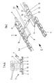
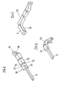
- the drawings show sections of a towing device (1) for a car wash, which consists of an endlessly rotating traction device (3), a plurality of sliding blocks (10) and towing rollers (7).
- the traction means (3) each have two strands, which are arranged on both sides of the track (8) for the vehicle wheel.
- the traction means can consist of two chains (4) or ropes (5) which are guided in a suitable manner in the longitudinal direction.
- Guide rails (9) are arranged inside and along the chains (4) or ropes (5) on both sides of the track (8), on which the sliding blocks (10) are mounted and guided in a longitudinally movable manner.
- the sliding blocks (10) have a U-shaped guide groove (29) with which the guide rails (9) are gripped.
- the sliding blocks (10) are supported on them and / or the track (8).
- the storage can be done on rollers or sliding surfaces.
- the guide grooves (29) are chamfered at the ends (not shown). This makes it easier to slide onto the rails (9).
- the sliding blocks (10) are fastened to the traction means (3) at intervals, the sliding blocks of a pair each being at the same height in the towing direction (23).
- the sliding blocks surround and guide the wheel (2) laterally, moving with it.
- the wheel (2) is pushed through the transverse and rotatably mounted trailing roller (7).
- the sliding blocks (10) are arranged in the towing direction (23) in front of the towing roller (7). They form a U-shaped drag shoe (12) from above.
- the drag roller (7) is rotatably mounted (17) at the rear end of the sliding blocks (10).
- the sliding blocks (10) are in turn connected to the adjacent strand of the traction means (3).
- transverse bolts (11) which are rotatably mounted on the chain links.
- each part (7, 10) can also be individually supported on the traction means (3) and guided separately in the towing direction (23).
- the sliding blocks (10) can also be connected to the traction means (3) via two bearing points, for example via the roller bearing (17).
- the sliding blocks (10) each consist of a plurality of links (13) which are arranged one behind the other in the towing direction (23) and are connected at the top by joints (14).
- the sliding blocks (10) have a smooth surface on the side and top.
- V-shaped recesses (15) are provided at the connection points on the lower side edge, so that the sliding block (10) can follow the bending of the rotating traction means (3) at the deflection points (cf. FIG. 4).
- the sliding blocks (10) surround a normal-wide vehicle wheel (2) with more or less lateral spacing. Should the towed wheel get out of track and run diagonally against a sliding block (10), it will be straightened again on this. Since the sliding blocks (10) are moved with the wheel (2), it does not ride up. In order to be able to guide the wheel safely, the sliding blocks (10) have a sufficient length, preferably at least 3/4 of the maximum expected wheel diameter.
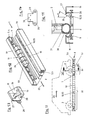
- the inside of the sliding blocks (10) facing the raceway (8) has a bevel (26) which serves to avoid damage to the tarnishing wheel and as special security against treading. This falls from the upper longitudinal edge of the sliding block (10) to the raceway (8) and goes a bit above the ground into a vertical drop, which prevents the tire (30) from reaching under (see FIG. 11).
- the angle of inclination alpha is preferably between 20 o and 30 o with respect to the vertical.
- the bevel (26) can be provided in all embodiments of the sliding blocks.
- the bevel (26) rejects the wheel touching and allows it to slide back onto the raceway (8).
- the two opposing bevels (26) of the sliding block pair also create a contact funnel that holds wide tires safely and in a centered manner and avoids one-sided ground contact of the wheel edges.
- the chamfer (26) means that the upper edges of the sliding blocks (10) are at a sufficient distance from the rim well (31) even for extreme low-profile tires.
- the upper inner longitudinal edge of the sliding blocks (10) can be rounded (see FIGS. 7 and 8).
- the sliding blocks (10) can also have a bevel (16) which is inclined inwards to the raceway (8). This serves as a guide surface to force the wheel (2) inward into the towing lane when starting. If necessary, the bevel can additionally have a component that slopes downward to make it easier to reach under and load wide tires.
- a cross-directional, rod-shaped deflector (18) is attached at the rear end near the ground in front of the trailing roller (7).
- a vehicle wheel (2) has a greater width than the free track between the sliding blocks (10) or is positioned with a strong lateral offset on the entrance side of the car wash, it is gripped, lifted and charged by one or both approaching sliding blocks (10) .
- Fig. 2 shows this position in which the wheel (2) rests on both sliding blocks (10) and is protected and dragged by them. To prevent it from rolling backwards, the drag roller (7) projects upwards over the sliding blocks (10).
- the sliding blocks (10) have a lateral, longitudinal shoulder which limits the contact area of the wheel (2).
- the traction means (3) here two chains (4), runs without or with a cover and in this case can be the same height or higher than the wheel contact area of the sliding blocks (10).
- the sliding blocks (10) project upward beyond the traction means (3).
- a wide tire can also protrude laterally over the traction means (3) without stressing it.
- the traction means (3) can also be provided with a cover (19) which surrounds the traction means (3) laterally and at the top.
- the cover (19) has a hook-shaped bend (20) on the inner longitudinal edge, on which the sliding blocks (10) are additionally guided laterally.
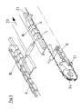
- FIGS. 6 and 9 shows a traction device (3) in the form of a steel cable (5) with drivers (6) arranged at intervals. Both strands usually consist of a steel cable.
- the drivers (6) consist of pressed-on metal rollers. They can also be designed differently, for example as balls.
- the sliding blocks (10) can be detached from the carriers (6) attached and can be attached and detached if necessary.
- catch hook (21) which projects laterally at the front end and which engages with the trailing driver (6) in a form-fitting manner.
- the catch hook (21) has a downwardly open slot (22) which overlaps the rope (5), the wider driver (6) being guided in a form-fitting manner on the slot walls.
- the driver (6) and the diaphragm walls are provided on the end face with matching conical or spherical shapes.
- Fig. 9 illustrates the drag position of a returning sliding block (10). This is guided on its wheel contact surface on a slide plate (not shown). If this slide plate is a bit lower than the lower rope run, both parts (3,10) can be moved separately.
- a deflector fork takes hold of the sliding block (10) or the towing shoe (12) at the deflection point, releases it from the traction device (3) and lets it slide onto the underlying sliding surface.
- the sliding blocks (10) are conveyed further by suitable drive means and lifted at the other end via a flap and suspended again in the rotating traction means (3).
- Fig. 9 shows this position.
- the rope (5) is moved together with the articulated sliding block (10) over a narrow deflection roller (4).
- This has trailing grooves (25) on the circumferential side for positive engagement with the drivers (6). These are additionally provided with a radial depression at the front end.
- the distance between the joints (14) of the sliding blocks (10) is matched to the diameter of the deflection roller (24) or to the pitch of a chain (4).
- the sliding blocks (10) are arranged in the towing direction (23) in front of and behind the towing roller (7) (cf. FIG. 10). Together they form an H-shaped drag shoe (12).
- the sliding blocks (10) in this embodiment also have a sufficient length in the area (33) located in front of the drag roller, preferably of at least 3/4 of the maximum expected wheel diameter.
- the rear sliding block area (32) is used to guide the front wheels in the event of a roller jump and the vehicle is pushed on the rear wheel by the next trailing roller (7).
- the front and rear wheels are guided from the front and rear sliding block areas (32, 33) of different tow rollers (7).
- the length of the rear sliding block area (32) or its distance from the next trailing roller (7) is matched to the expected wheelbases of the vehicles.
- the currently smallest known car wheelbase is approximately 1.80 m.
- a distance of the sliding block end to the next rear drag roller (7) of approx. 1.70 m is selected.
- With a trailing roller distance of approx. 3.20 m this results in a length of the rear sliding block area (32) of 1.50 m.
- the wheelbases are over 2 m.
- a distance of 2.30 m or a length of the rear sliding block area (32) of 0.90 m has also proven to be sufficient.
- a sliding block which is continuous over the entire length of the individual traction means (3) and in this respect is endless be used.
- the sliding blocks (10) have a longitudinal step (27) on the rear upper edge.
- the L-shaped covers (19) of the traction means (3) engage in them with play and prevent the sliding blocks (10) from lifting off (cf. FIG. 11).
- the sliding blocks (10) are thereby additionally supported against lateral forces exerted by the wheel (2) and cannot tilt.
- the bevel (26) there may still be a reduced top surface of the sliding blocks as a wheel support. This preferably projects upwards over the traction element cover (19) in order to lift a charged wide tire over it during transport. Depending on the width of the tire, the wheel can be positioned in the space between the traction device covers (19) when entering the car wash or, if the width is too large, on the traction device covers (19). In order to prevent the sliding blocks (10) from rolling backwards, the drag roller (7) projects upwards above the sliding blocks (10).
- the sliding blocks (10) each consist of a series of several independent links (13) which are arranged one behind the other in the towing direction (23). They have a slight distance between them in order to be able to follow the bending of the rotating traction means (3) at the deflection points.
- the links (13) can also abut one another and have V-shaped recesses on the lower side edge.
- the links are individually attached to the traction mechanism (3).
- a chain (4) they are mounted on the link plates (28).
- these link plates (28) are provided with an enlarged mounting plate (34) which extends between the chain eyes (35) extends above.
- the mounting plate (34) lies flat against the rear wall of the links (13) and is connected to it at several points by means of screws or bolts (11) above the normal bracket height. The connection points are thus accessible without dismantling the chain (4) and allow the links (13) to be replaced quickly.
- the drag rollers (7) are alternatively rotatably mounted on the sliding blocks (10) or directly connected to the traction means (3).
- they can have a longitudinal guide, for example in the form of lateral, radially projecting collar rollers which engage in a floor channel.
- the towing device (1) can be present in a car wash system once or twice with corresponding traction means synchronization.
Landscapes
- Engineering & Computer Science (AREA)
- Mechanical Engineering (AREA)
- Vehicle Cleaning, Maintenance, Repair, Refitting, And Outriggers (AREA)
Applications Claiming Priority (4)
| Application Number | Priority Date | Filing Date | Title |
|---|---|---|---|
| DE3830910 | 1988-09-10 | ||
| DE19883830910 DE3830910C1 (fr) | 1988-09-10 | 1988-09-10 | |
| DE3843643 | 1988-12-23 | ||
| DE19883843643 DE3843643A1 (de) | 1988-09-10 | 1988-12-23 | Schleppvorrichtung fuer fahrzeugraeder in autowaschanlagen |
Publications (2)
| Publication Number | Publication Date |
|---|---|
| EP0359162A2 true EP0359162A2 (fr) | 1990-03-21 |
| EP0359162A3 EP0359162A3 (fr) | 1991-01-09 |
Family
ID=25872112
Family Applications (1)
| Application Number | Title | Priority Date | Filing Date |
|---|---|---|---|
| EP19890116732 Ceased EP0359162A3 (fr) | 1988-09-10 | 1989-09-09 | Installation de halage pour roue de véhicule dans une installation de lavage de voiture |
Country Status (2)
| Country | Link |
|---|---|
| EP (1) | EP0359162A3 (fr) |
| DE (1) | DE3843643A1 (fr) |
Cited By (4)
| Publication number | Priority date | Publication date | Assignee | Title |
|---|---|---|---|---|
| EP0688707A1 (fr) * | 1994-05-25 | 1995-12-27 | Thaler SKB-GmbH, Spulanlagen - Kabelverlegemaschinen - Baugeräte | Dispositif pour le transport de véhicules au travers d'un dispositif de lavage |
| CN102107777A (zh) * | 2009-12-24 | 2011-06-29 | 同方威视技术股份有限公司 | 车辆输送装置和具有该车辆输送装置的车辆辐射检测系统 |
| CN101633351B (zh) * | 2008-07-23 | 2012-02-15 | 同方威视技术股份有限公司 | 车辆输送装置和具有该车辆输送装置的车辆辐射检测系统 |
| CN102530474B (zh) * | 2008-07-23 | 2014-03-26 | 同方威视技术股份有限公司 | 用于车辆的输送装置的伸缩杆单元 |
Families Citing this family (2)
| Publication number | Priority date | Publication date | Assignee | Title |
|---|---|---|---|---|
| DE102008034571A1 (de) | 2008-07-24 | 2010-02-04 | Wash Tec Holding Gmbh | Radleitschiene, Fahrzeugwaschanlage und Verfahren zum mittigen Positionieren eines Fahrzeugs |
| DE202008009959U1 (de) | 2008-07-24 | 2009-12-10 | Washtec Holding Gmbh | Radleitschiene und Fahrzeugwaschanlage |
Family Cites Families (6)
| Publication number | Priority date | Publication date | Assignee | Title |
|---|---|---|---|---|
| US3058433A (en) * | 1959-12-23 | 1962-10-16 | Mowatt M Hurst | Conveyor for vehicles |
| US3596606A (en) * | 1968-11-12 | 1971-08-03 | Sherman Car Wash Equip Co | Vehicle conveyor |
| DE2017089A1 (de) * | 1970-04-10 | 1971-10-28 | Keindienst & Co Maschinenfabri | Vorrichtung zum Transportieren eines Fahrzeuges durch eine Autowaschstraße |
| US3731637A (en) * | 1971-06-03 | 1973-05-08 | Foundation And Bridge Corp | Pusher device |
| NL7215336A (fr) * | 1972-11-13 | 1974-05-15 | ||
| US4194449A (en) * | 1977-01-03 | 1980-03-25 | Breau Arisma J | Double dolly |
-
1988
- 1988-12-23 DE DE19883843643 patent/DE3843643A1/de active Granted
-
1989
- 1989-09-09 EP EP19890116732 patent/EP0359162A3/fr not_active Ceased
Cited By (4)
| Publication number | Priority date | Publication date | Assignee | Title |
|---|---|---|---|---|
| EP0688707A1 (fr) * | 1994-05-25 | 1995-12-27 | Thaler SKB-GmbH, Spulanlagen - Kabelverlegemaschinen - Baugeräte | Dispositif pour le transport de véhicules au travers d'un dispositif de lavage |
| CN101633351B (zh) * | 2008-07-23 | 2012-02-15 | 同方威视技术股份有限公司 | 车辆输送装置和具有该车辆输送装置的车辆辐射检测系统 |
| CN102530474B (zh) * | 2008-07-23 | 2014-03-26 | 同方威视技术股份有限公司 | 用于车辆的输送装置的伸缩杆单元 |
| CN102107777A (zh) * | 2009-12-24 | 2011-06-29 | 同方威视技术股份有限公司 | 车辆输送装置和具有该车辆输送装置的车辆辐射检测系统 |
Also Published As
| Publication number | Publication date |
|---|---|
| EP0359162A3 (fr) | 1991-01-09 |
| DE3843643A1 (de) | 1990-06-28 |
Similar Documents
| Publication | Publication Date | Title |
|---|---|---|
| WO2017032675A1 (fr) | Poulie à courroie pour installation d'ascenseur | |
| DE202005016966U1 (de) | Laufrollenanordnung für die Kette eines Raupenfahrwerkes | |
| DE10156992B4 (de) | Trittelementbefestigung für Personenbeförderer | |
| DE3732542C1 (en) | Apparatus for conveying motor vehicles in vehicle washing installations | |
| EP0359162A2 (fr) | Installation de halage pour roue de véhicule dans une installation de lavage de voiture | |
| DE3830910C1 (fr) | ||
| DE8909620U1 (de) | Rad für Wagen o.dgl. mit einer Vorrichtung zur Blockierung auf einer schiefen Ebene | |
| DE60004787T2 (de) | Aufhebeanordnung für raupenfahrzeugrad | |
| EP0431141A1 (fr) | Chariot d'entreposage et de transfert de porteurs de marchandises. | |
| DE2017089A1 (de) | Vorrichtung zum Transportieren eines Fahrzeuges durch eine Autowaschstraße | |
| DE10011799B4 (de) | Vorrichtung zum Anheben von in einem angetriebenen Förderstrang befindlichen Unterlagen | |
| DE102012107923A1 (de) | Zwischenträger zum hängenden Transport eines Objekts sowie Zwischenträgereinheit mit einem solchen Zwischenträger und Hängeförderanlage mit einer solchen Zwischenträgereinheit | |
| CH683516A5 (de) | Sicherheitsvorrichtung für einen Laufwagen an einer Seilkran-Anlage. | |
| EP2757003B1 (fr) | Dispositif de convoyage pour véhicules automobiles | |
| DE102018104706A1 (de) | Auffahrschiene | |
| DE20103074U1 (de) | Fahrtreppe oder Fahrsteig | |
| DE20214518U1 (de) | Schleppvorrichtung für Fahrzeugräder in Autowaschanlagen | |
| DE4418027A1 (de) | Vorrichtung zur Beförderung von Kraftfahrzeugen durch eine Waschanlage | |
| DE20114170U1 (de) | Schleppvorrichtung für Fahrzeugräder in Autowaschanlagen | |
| EP4070975A1 (fr) | Rouleau de bâche destiné au stockage mobile d'une bâche | |
| DE2802401A1 (de) | Haengebahnanlage | |
| DE684184C (de) | Fahrtreppe | |
| DE10335300A1 (de) | Stahlgelenkkette | |
| DE1431544C (fr) | ||
| DE1580899C3 (de) | Rolltreppe oder Rollsteig mit Plattenwagen |
Legal Events
| Date | Code | Title | Description |
|---|---|---|---|
| PUAI | Public reference made under article 153(3) epc to a published international application that has entered the european phase |
Free format text: ORIGINAL CODE: 0009012 |
|
| AK | Designated contracting states |
Kind code of ref document: A2 Designated state(s): DE ES FR GB IT |
|
| PUAL | Search report despatched |
Free format text: ORIGINAL CODE: 0009013 |
|
| AK | Designated contracting states |
Kind code of ref document: A3 Designated state(s): DE ES FR GB IT |
|
| 17P | Request for examination filed |
Effective date: 19910619 |
|
| 17Q | First examination report despatched |
Effective date: 19921002 |
|
| STAA | Information on the status of an ep patent application or granted ep patent |
Free format text: STATUS: THE APPLICATION HAS BEEN REFUSED |
|
| 18R | Application refused |
Effective date: 19930322 |