EP0359167A2 - Réfractomètre utilisant une division d'ouverture en dépendance de l'index de réfraction - Google Patents
Réfractomètre utilisant une division d'ouverture en dépendance de l'index de réfraction Download PDFInfo
- Publication number
- EP0359167A2 EP0359167A2 EP89116738A EP89116738A EP0359167A2 EP 0359167 A2 EP0359167 A2 EP 0359167A2 EP 89116738 A EP89116738 A EP 89116738A EP 89116738 A EP89116738 A EP 89116738A EP 0359167 A2 EP0359167 A2 EP 0359167A2
- Authority
- EP
- European Patent Office
- Prior art keywords
- measuring
- receiver
- refractometer
- light
- refractive index
- Prior art date
- Legal status (The legal status is an assumption and is not a legal conclusion. Google has not performed a legal analysis and makes no representation as to the accuracy of the status listed.)
- Withdrawn
Links
Images

Classifications
-
- G—PHYSICS
- G01—MEASURING; TESTING
- G01N—INVESTIGATING OR ANALYSING MATERIALS BY DETERMINING THEIR CHEMICAL OR PHYSICAL PROPERTIES
- G01N21/00—Investigating or analysing materials by the use of optical means, i.e. using sub-millimetre waves, infrared, visible or ultraviolet light
- G01N21/17—Systems in which incident light is modified in accordance with the properties of the material investigated
- G01N21/41—Refractivity; Phase-affecting properties, e.g. optical path length
- G01N21/43—Refractivity; Phase-affecting properties, e.g. optical path length by measuring critical angle
-
- G—PHYSICS
- G01—MEASURING; TESTING
- G01J—MEASUREMENT OF INTENSITY, VELOCITY, SPECTRAL CONTENT, POLARISATION, PHASE OR PULSE CHARACTERISTICS OF INFRARED, VISIBLE OR ULTRAVIOLET LIGHT; COLORIMETRY; RADIATION PYROMETRY
- G01J3/00—Spectrometry; Spectrophotometry; Monochromators; Measuring colours
- G01J3/28—Investigating the spectrum
- G01J3/2803—Investigating the spectrum using photoelectric array detector
-
- G—PHYSICS
- G01—MEASURING; TESTING
- G01N—INVESTIGATING OR ANALYSING MATERIALS BY DETERMINING THEIR CHEMICAL OR PHYSICAL PROPERTIES
- G01N2201/00—Features of devices classified in G01N21/00
- G01N2201/08—Optical fibres; light guides
- G01N2201/0826—Fibre array at source, distributing
-
- G—PHYSICS
- G01—MEASURING; TESTING
- G01N—INVESTIGATING OR ANALYSING MATERIALS BY DETERMINING THEIR CHEMICAL OR PHYSICAL PROPERTIES
- G01N2201/00—Features of devices classified in G01N21/00
- G01N2201/08—Optical fibres; light guides
- G01N2201/0833—Fibre array at detector, resolving
Definitions
- the present invention relates to a refractometer, consisting of a measuring prism with a measuring surface, which is in optical contact with the sample to be measured, an illumination device with a light beam that falls on the measuring surface under such an angular range that the critical angle for toltal reflection in it is included, as well as a photoelectric receiver.
- Such a device is e.g. known from DE-AS 1 266 016.
- a comparison photo cell is always hit by the reflected light and another comparison photo cell always receives only scattered light.
- Such a refractometer only has a sharp light-dark boundary when measuring with monochromatic light or when - when illuminated with white light - a so-called compensator is used to compensate for the dispersion of the white light (Abbe refractometer).
- Such a refractometer is not suitable for measuring the refractive index curve (refractive index as a function of the wavelength). It also has the disadvantage that all parts necessary for the measurement are arranged in the immediate vicinity of the measuring prism.
- the object of the present invention is therefore to provide a refractometer which is as simple as possible in construction, in which as few parts as possible have to be in the vicinity of the measuring prism and which is also suitable for measuring the course of the refractive index.
- the object is achieved based on a structure specified in the preamble of claim 1 according to the invention in that the light reflected from the measuring surface is focused by optical means on a receiver or a receiver surface.
- the refractive index-dependent aperture is determined by focusing the reflected radiation on a receiver or a receiver area measured and evaluated as a change in intensity. Since an aperture rating is made for each wavelength of radiation corresponding to the refractive index belonging to it, which is independent of the aperture rating of the other wavelengths, the course of the refractive index can also be measured with the aid of a spectrometer.
- the spectrometer it is particularly advantageous to connect the spectrometer to the measuring head housing via a light guide, the entry surface of the light guide serving as a receiver surface on which the light reflected by the measuring prism is focused.
- the measuring head housing can be constructed very compactly, that no moving parts are necessary and that the measuring head housing is explosion-proof, since in it no electrical voltages and no large optical powers are necessary.
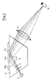
- (11) denotes a measuring prism on whose measuring surface (11m) the sample (12) is applied, the refractive index of which is measured.
- the measuring surface (11m) is illuminated by the beam (13s) diverging from the light source (13).
- the radiation reflected from the measuring surface (11m) is focused by the objective (14) on the receiver (15) after exiting the measuring prism (11).
- a characteristic part (t) of the aperture (a) emanating from the light source is reflected on the measuring surface (11m) and focused on the receiver (15).
- the refractive index-dependent aperture part impinging on the receiver and thus the intensity measured by the receiver is therefore a direct measure of the refractive index n of the sample (12). If a continuum emitter is used as the light source (13) and e.g.
- the refractive index quotients n ( ⁇ ) / N ( ⁇ ) can be determined simultaneously in a large spectral range by measuring the wavelength-dependent reflectivity R ( ⁇ ) of the measuring surface, which is converted into the dispersion curve n ( ⁇ ) using a calibration curve can.
- the arrangement shown in FIG. 1, like the arrangements shown in FIGS. 2 and 3, is also suitable for measurement at only one or a few wavelengths.
- a light emitting diode or a line emitter can be used.
- a filter or an exchange device with several filters can be arranged before or after the measuring prism.
- the receiver can be used with a photodiode.
- a diode line spectrometer is used as the receiver to record the refractive index curve
- either the input slit of the spectrometer or - in a particularly advantageous embodiment - is shown at the location of the receiver (15) in FIG staltung of the invention - the input surface of an optical fiber that leads to the spectrometer, arranged.
- the latter embodiment of the invention is shown in FIG. 2, in which it is also shown that the light beam striking the measuring surface can also be convergent.
- the light source in FIG. 2 is connected to the measuring prism via an optical fiber (27).
- the measuring prism (22) shown in Figure 2 has the shape of a hemisphere; therefore no further optical parts are required.
- (22m) denotes the flat measuring surface of the measuring prism, which is fastened in a measuring head housing (26), which is designed with holes (26b) for fastening on its flange-like edge.
- the light guide (27) leads to a lamp housing, not shown, in which e.g. a xenon, halogen, deuterium or metal halide lamp is included.
- the end face (27e) of the light guide the core of which e.g. has a diameter of 200 ⁇ m, serves as a cold point light source. It is arranged at a distance from the spherical surface (22k) that is larger than its focal length, so that the beam path is convergent in the interior of the hemisphere.
- the end surface (27e) of the light guide (27) is imaged into the receiver surface (25) by the spherical surface (22k) of the measuring prism (22m).
- the starting surface (28a) of the light guide (28) is arranged, which has a core diameter of e.g. 600 ⁇ m and leads to a diode line spectrometer, not shown.
- the light guides (27) and (28) are connected to the lamp housing and diode array spectrometer in the e.g. known from DE-OS 3 701 721.
- Liquid, pasty or solid substances can be used for the measurement, the latter having to have a flat surface which is brought into optical contact with the measuring surface with a liquid whose refractive index is equal to or greater than the refractive index N of the measuring prism.
- FIG. 3 shows an exemplary embodiment for the measurement of the refractive index or the course of the refractive index on a substance which is located in a reaction vessel.
- the spherical section (32k) firmly connected to the measuring head housing (36) together with the observation window (39) of the reaction vessel forms the hemisphere of the measuring prism (32), so that the measuring surface (32m) lies on the side of the observation window facing away from the spherical section.
- Spherical section (32k) and observation window (39) are expediently made from the same type of glass, so that they have the same refractive index and refractive index curve.
- the optical contact is e.g. achieved by a suitable liquid with a sufficiently high refractive index or by cementing.
Landscapes
- Physics & Mathematics (AREA)
- Health & Medical Sciences (AREA)
- Life Sciences & Earth Sciences (AREA)
- Chemical & Material Sciences (AREA)
- Analytical Chemistry (AREA)
- Biochemistry (AREA)
- General Health & Medical Sciences (AREA)
- General Physics & Mathematics (AREA)
- Immunology (AREA)
- Pathology (AREA)
- Investigating Or Analysing Materials By Optical Means (AREA)
Applications Claiming Priority (2)
| Application Number | Priority Date | Filing Date | Title |
|---|---|---|---|
| DE3831346 | 1988-09-15 | ||
| DE19883831346 DE3831346A1 (de) | 1988-09-15 | 1988-09-15 | Refraktometer mit brechzahlabhaengiger aperturteilung |
Publications (2)
| Publication Number | Publication Date |
|---|---|
| EP0359167A2 true EP0359167A2 (fr) | 1990-03-21 |
| EP0359167A3 EP0359167A3 (fr) | 1991-06-05 |
Family
ID=6362992
Family Applications (1)
| Application Number | Title | Priority Date | Filing Date |
|---|---|---|---|
| EP19890116738 Withdrawn EP0359167A3 (fr) | 1988-09-15 | 1989-09-09 | Réfractomètre utilisant une division d'ouverture en dépendance de l'index de réfraction |
Country Status (3)
| Country | Link |
|---|---|
| EP (1) | EP0359167A3 (fr) |
| JP (1) | JPH02114151A (fr) |
| DE (1) | DE3831346A1 (fr) |
Cited By (8)
| Publication number | Priority date | Publication date | Assignee | Title |
|---|---|---|---|---|
| US5309288A (en) * | 1991-09-18 | 1994-05-03 | Janesko Oy | Prismatic device for use with process refractometers |
| US5742382A (en) * | 1993-09-07 | 1998-04-21 | Janeksko Oy | Refractometer |
| RU2113710C1 (ru) * | 1997-12-26 | 1998-06-20 | Закрытое акционерное общество Международная компания "Луч" | Автоматический рефрактометр для контроля параметров жидких сред |
| CN102590142A (zh) * | 2012-03-12 | 2012-07-18 | 南开大学 | 聚焦全内反射法测量物质折射率分布 |
| DE102014201079A1 (de) | 2013-01-23 | 2014-07-24 | Janesko Oy | Verfahren zur Messung eines Brechungsindexes und Refraktometer |
| US9632025B2 (en) | 2014-05-13 | 2017-04-25 | Janesko Oy | Method and measuring device for continuously measuring the abbe number |
| US10113960B2 (en) | 2015-06-29 | 2018-10-30 | Janesko Oy | Arrangement in connection with measuring window of refractometer, and refractometer |
| US10657354B2 (en) * | 2015-01-23 | 2020-05-19 | Abilma LLC | Compact system for registering papillary ridge patterns |
Families Citing this family (4)
| Publication number | Priority date | Publication date | Assignee | Title |
|---|---|---|---|---|
| US5641230A (en) * | 1993-04-15 | 1997-06-24 | Japan Energy Corporation | Method of determining cloud points and cloud point meter |
| US5565978A (en) * | 1993-04-15 | 1996-10-15 | Japan Energy Corporation | Total-reflection type refractive index sensor |
| FI108259B (fi) * | 1998-01-30 | 2001-12-14 | Janesko Oy | Refraktometri |
| FI124951B (fi) * | 2010-02-05 | 2015-04-15 | Jan Kåhre | Optinen järjestelmä |
Family Cites Families (4)
| Publication number | Priority date | Publication date | Assignee | Title |
|---|---|---|---|---|
| US2885923A (en) * | 1954-08-13 | 1959-05-12 | Phillips Petroleum Co | Reflection refractometer |
| JPS554262B2 (fr) * | 1975-03-25 | 1980-01-29 | ||
| DE3414261A1 (de) * | 1984-04-14 | 1985-10-24 | Fa. Carl Zeiss, 7920 Heidenheim | Interferenz-refraktometer |
| DE3701721A1 (de) * | 1987-01-22 | 1988-08-04 | Zeiss Carl Fa | Remissionsmessgeraet zur beruehrungslosen messung |
-
1988
- 1988-09-15 DE DE19883831346 patent/DE3831346A1/de not_active Withdrawn
-
1989
- 1989-09-09 EP EP19890116738 patent/EP0359167A3/fr not_active Withdrawn
- 1989-09-14 JP JP23737089A patent/JPH02114151A/ja active Pending
Cited By (10)
| Publication number | Priority date | Publication date | Assignee | Title |
|---|---|---|---|---|
| US5309288A (en) * | 1991-09-18 | 1994-05-03 | Janesko Oy | Prismatic device for use with process refractometers |
| US5742382A (en) * | 1993-09-07 | 1998-04-21 | Janeksko Oy | Refractometer |
| RU2113710C1 (ru) * | 1997-12-26 | 1998-06-20 | Закрытое акционерное общество Международная компания "Луч" | Автоматический рефрактометр для контроля параметров жидких сред |
| CN102590142A (zh) * | 2012-03-12 | 2012-07-18 | 南开大学 | 聚焦全内反射法测量物质折射率分布 |
| CN102590142B (zh) * | 2012-03-12 | 2014-03-26 | 南开大学 | 聚焦全内反射法测量物质折射率分布 |
| DE102014201079A1 (de) | 2013-01-23 | 2014-07-24 | Janesko Oy | Verfahren zur Messung eines Brechungsindexes und Refraktometer |
| US9719919B2 (en) | 2013-01-23 | 2017-08-01 | Janesko Oy | Method for measuring refractive index, and refractometer |
| US9632025B2 (en) | 2014-05-13 | 2017-04-25 | Janesko Oy | Method and measuring device for continuously measuring the abbe number |
| US10657354B2 (en) * | 2015-01-23 | 2020-05-19 | Abilma LLC | Compact system for registering papillary ridge patterns |
| US10113960B2 (en) | 2015-06-29 | 2018-10-30 | Janesko Oy | Arrangement in connection with measuring window of refractometer, and refractometer |
Also Published As
| Publication number | Publication date |
|---|---|
| DE3831346A1 (de) | 1990-04-05 |
| EP0359167A3 (fr) | 1991-06-05 |
| JPH02114151A (ja) | 1990-04-26 |
Similar Documents
| Publication | Publication Date | Title |
|---|---|---|
| DE2739585C2 (de) | Spektrophotometer | |
| EP0655128B1 (fr) | Systeme spectroscopiques pour analyser de faibles et d'infimes quantites de substances | |
| EP0209860B1 (fr) | Appareil de mesure de la réflexion pour mesure sans contact | |
| DE112012004766B4 (de) | Durchflusszelle und Flüssigkeitsanalysegerät | |
| DE3414261A1 (de) | Interferenz-refraktometer | |
| WO2001046656A1 (fr) | Spectrometre miniaturise | |
| EP0279191A2 (fr) | Dispositif pour la mesure sans contact de la rémission | |
| DE2851455C3 (de) | Vorrichtung zur Bestimmung von das Glanzvermögen von Oberflächen charakterisierenden Remissionswerten | |
| EP0154875A2 (fr) | Appareil pour la détermination de la réflectivité diffuse d'un surface échantillon de petites dimensions | |
| EP0458223A2 (fr) | Appareil pour mesurer l'absorption d'échantillons transparents d'une forme défavorable | |
| DE102016212507A1 (de) | Chromatisch-konfokaler Bereichssensor mit Kamerateil | |
| EP0359167A2 (fr) | Réfractomètre utilisant une division d'ouverture en dépendance de l'index de réfraction | |
| DE3304780C2 (fr) | ||
| WO2005114146A1 (fr) | Dispositif pour l'analyse ou la mesure d'absorption concernant une petite quantite de substance liquide a l'aide de lumiere | |
| DE2363202C3 (de) | Optischer Schnellanalysator | |
| DE4200869A1 (de) | Infrarot mikroskop-spektrometer | |
| DE4343872C2 (de) | Vorrichtung mit einem Spektralphotometer und Lichtleitern | |
| DE10107210C1 (de) | Mikroskop | |
| DE102022128701A1 (de) | Messvorrichtung für abgeschwächte totalreflexion, die zu einer raman-spektralmessung in der lage ist | |
| DE4138679C2 (de) | Gerät zur Bestimmung visueller Oberflächeneigenschaften | |
| DE10149879B4 (de) | Vorrichtung zur spektralphotometrischen Analyse von flüssigen Medien | |
| DE10021379A1 (de) | Optische Messanordnung insbesondere zur Schichtdickenmessung | |
| DE10316514A1 (de) | Vorrichtung zur IR-spektrometrischen Analyse eines festen, flüssigen oder gasförmigen Mediums | |
| DE1203980B (de) | Einrichtung zum Messen und UEberwachen des Brechungsindexes von Fluessigkeiten od. dgl. | |
| EP0327499B1 (fr) | Tête de mesure |
Legal Events
| Date | Code | Title | Description |
|---|---|---|---|
| PUAI | Public reference made under article 153(3) epc to a published international application that has entered the european phase |
Free format text: ORIGINAL CODE: 0009012 |
|
| AK | Designated contracting states |
Kind code of ref document: A2 Designated state(s): CH DE FR GB IT LI |
|
| PUAL | Search report despatched |
Free format text: ORIGINAL CODE: 0009013 |
|
| AK | Designated contracting states |
Kind code of ref document: A3 Designated state(s): CH DE FR GB IT LI |
|
| STAA | Information on the status of an ep patent application or granted ep patent |
Free format text: STATUS: THE APPLICATION IS DEEMED TO BE WITHDRAWN |
|
| 18D | Application deemed to be withdrawn |
Effective date: 19911206 |