EP0359247A2 - Capteur de rotation - Google Patents
Capteur de rotation Download PDFInfo
- Publication number
- EP0359247A2 EP0359247A2 EP89116986A EP89116986A EP0359247A2 EP 0359247 A2 EP0359247 A2 EP 0359247A2 EP 89116986 A EP89116986 A EP 89116986A EP 89116986 A EP89116986 A EP 89116986A EP 0359247 A2 EP0359247 A2 EP 0359247A2
- Authority
- EP
- European Patent Office
- Prior art keywords
- bearing
- stator
- encoder according
- shaft
- roller bearings
- Prior art date
- Legal status (The legal status is an assumption and is not a legal conclusion. Google has not performed a legal analysis and makes no representation as to the accuracy of the status listed.)
- Withdrawn
Links
Images
Classifications
-
- G—PHYSICS
- G01—MEASURING; TESTING
- G01D—MEASURING NOT SPECIALLY ADAPTED FOR A SPECIFIC VARIABLE; ARRANGEMENTS FOR MEASURING TWO OR MORE VARIABLES NOT COVERED IN A SINGLE OTHER SUBCLASS; TARIFF METERING APPARATUS; MEASURING OR TESTING NOT OTHERWISE PROVIDED FOR
- G01D5/00—Mechanical means for transferring the output of a sensing member; Means for converting the output of a sensing member to another variable where the form or nature of the sensing member does not constrain the means for converting; Transducers not specially adapted for a specific variable
- G01D5/26—Mechanical means for transferring the output of a sensing member; Means for converting the output of a sensing member to another variable where the form or nature of the sensing member does not constrain the means for converting; Transducers not specially adapted for a specific variable characterised by optical transfer means, i.e. using infrared, visible, or ultraviolet light
- G01D5/32—Mechanical means for transferring the output of a sensing member; Means for converting the output of a sensing member to another variable where the form or nature of the sensing member does not constrain the means for converting; Transducers not specially adapted for a specific variable characterised by optical transfer means, i.e. using infrared, visible, or ultraviolet light with attenuation or whole or partial obturation of beams of light
- G01D5/34—Mechanical means for transferring the output of a sensing member; Means for converting the output of a sensing member to another variable where the form or nature of the sensing member does not constrain the means for converting; Transducers not specially adapted for a specific variable characterised by optical transfer means, i.e. using infrared, visible, or ultraviolet light with attenuation or whole or partial obturation of beams of light the beams of light being detected by photocells
- G01D5/347—Mechanical means for transferring the output of a sensing member; Means for converting the output of a sensing member to another variable where the form or nature of the sensing member does not constrain the means for converting; Transducers not specially adapted for a specific variable characterised by optical transfer means, i.e. using infrared, visible, or ultraviolet light with attenuation or whole or partial obturation of beams of light the beams of light being detected by photocells using displacement encoding scales
- G01D5/3473—Circular or rotary encoders
Definitions
- the invention relates to a rotary encoder with a stator, which is connected to a housing and in which a shaft is mounted via two roller bearings, on which a graduated disk is attached, to which an electro-optical scanning unit fixed to the stator is assigned.
- Light-emitting diodes or filament lamps are usually used to scan the graduation of the indexing disk in rotary encoders of the type mentioned. Maintaining a certain distance between a scanning or graticule arranged on the side of the light-emitting diode / filament lamp and the graduated disk is of considerable importance for the measuring accuracy. Light-emitting diodes and filament lamps are known to form a light cone. In order to avoid measurement errors, the distance between the scanning plate and the indexing disk must be kept as constant as possible.
- the encoder is also mechanically designed so that a Bearing shaft is preferably received in a bearing flange via deep groove ball bearings. One end of the shaft is available for attachment to the outside via the bearing flange and the indexing plate is arranged at the inward end of the shaft. A cover protecting the entire system including a printed circuit board is attached to the bearing flange.
- the invention is therefore based on the object of avoiding the shortcomings indicated and improving a rotary encoder of the type mentioned at the outset in such a way that a simple distance between the scanning plate and the indexing disk can be ensured using simple constructional means with a low overall height.
- this technical problem is solved according to the invention in a rotary encoder with a stator, which is connected to a surrounding housing and in which a shaft is mounted via two roller bearings, to which a graduated disk is attached, which is assigned an electro-optical scanning unit fixed to the stator that the stator is formed by two interconnected bearing flanges, which are designed so that in the connected Zu the bearing flanges remained free an annular space receiving the indexing plate and that the outer ring of one roller bearing is fixed to one bearing flange and the outer ring of the other roller bearing is fixed to the other bearing flange.
- the inner rings of the roller bearings designed as shoulder ball bearings are preferably fixed on the shaft, which can be a hollow or solid shaft, by gluing, and the bearing flanges are screwed together to form the stator.
- the inner rings of the roller bearings are preloaded axially, preferably in the sense of increasing the mutual distance, for example by a pressure-elastic element arranged between the inner rings, in particular a compression spring.
- the bearing flanges screwed together to form the stator are preferably connected to the housing via a double membrane coupling.
- indexing disk and the scanning plate or the entire scanning unit lie inside the two bearing flanges achieves the lowest overall height that is possible at all. This is particularly favorable for hollow shaft encoders.
- the outer rings of the rolling bearings e.g. B. ball bearings can be fixed in the bearing flanges, for example by gluing.
- the inner rings of the two rolling bearings which are under axial, defined prestressing by the elastic element, are glued to the bearing shaft.
- B. an anaerobic curing adhesive is used. This ensures that the clearance of the bearing shaft or the rolling bearing is retained.
- a particularly favorable bearing geometry also results from the fact that the roller bearings can be attached to the extremely possible position of the stator, which nevertheless results in a compact construction of the rotary encoder. This has a positive effect on the service life of the rolling bearings and the permissible vertical load, i.e. the stability of the encoder as a whole, is significantly increased.
- the bores of the two bearing flanges for receiving the outer rings of the roller bearings can have the same diameter, which results in a further simplification in the manufacture of the individual parts and in the assembly thereof to form the rotary encoder according to the invention.
- the construction according to the invention can be used both for solid shaft encoders and for hollow shaft encoders.
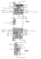
- the encoder shown has a double diaphragm coupling 8 on to compensate for unavoidable misalignments of a drive shaft, not shown, of an external drive to the bearing shaft 7 or to two bearing flanges 6.1 and 6.2, which form a stator 13 in the screwed state.
- a membrane 8b is screwed to the stator 13 and the other membrane 8a to a fastening ring 10, which is part of a housing 12.
- the mounting ring 10 also serves as a centering ring and mounting flange for the rotary encoder to be suspended on the mounting surface of the external drive.
- the bearing shaft 7 is rotatably supported by means of two roller bearings 11.
- a dividing disk 1 is fastened, which engages in an annular space formed by the stepped shape of the bearing flanges 6.1 and 6.2.
- the graduated disk 1 is assigned a scanning unit 15 attached to the bearing flange 6.2, which has a scanning or reticle 2, at least one light-emitting diode 5 being arranged on one side of the scanning plate 2 and at least one photoelectric receiver 4 on the other side of the scanning plate 2.
- the measuring graduation of the graduated disk 1 is thus scanned by the receiver 4 in relation to the line pattern of the scanning plate 2 in transmitted light from the light-emitting diode 5.
- the entire scanning unit 15 is thus arranged in the space enclosed by the bearing flanges 6.1, 6.2.
- the light-emitting diode 5 forms a light cone 16, as a result of which the scanning of the measuring graduation of the graduated disk 1 is dependent on changes in distance between the scanning plate 2 and the graduated disk 1.
- the inner rings 11a are the Rolling bearing 11 axially clamped relative to the outer rings 11b, so that the axial bearing play is eliminated.
- an axially acting helical spring 9 is inserted between the inner ring 11a of the roller bearing 11 and a collar or shaft flange 18, which coaxially surrounds the bearing shaft 7.
- the outer rings 11b of the roller bearings 11 are connected to the bearing flanges 6.1 and 6.2, which preferably have holes of the same size for receiving these outer rings, by adhesive bonding.
- the roller bearings 11 are installed in such a way that the bearing shaft 7 is pushed into the inner ring 11a of the roller bearing 11 arranged in the bearing flange 6.2 and then the coil spring 9 is pushed over the bearing shaft 7 and then the bearing flange 6.1 onto the bearing shaft 7.
- adhesive e.g. B. an anaerobic curing adhesive, applied to glue the inner rings 11a of the roller bearings 11 to the shaft 7, the two bearing flanges 6.1 and 6.2 being screwed together within the setting or curing time of the adhesive and then forming the stator 13.
- the scanning unit 15 Due to the construction enclosing the scanning unit and the play compensation due to the axial bracing of the roller bearings 11, signal fluctuations when scanning the indexing disk 1 by the scanning unit 15 are excluded. Since the axial fixing of the shaft 7 via a preload of the roller bearings 11 has no influence on the scanning stone Unit 15, the scanning unit 15 can in principle be designed as desired. For example, the invention can be applied to incremental rotary encoders as well as to absolute encoders and the scanning can be carried out using the transmitted light or reflection method.
Landscapes
- Physics & Mathematics (AREA)
- General Physics & Mathematics (AREA)
- Optical Transform (AREA)
- Transmission And Conversion Of Sensor Element Output (AREA)
Applications Claiming Priority (2)
| Application Number | Priority Date | Filing Date | Title |
|---|---|---|---|
| AT227388 | 1988-09-16 | ||
| AT2273/88 | 1988-09-16 |
Publications (2)
| Publication Number | Publication Date |
|---|---|
| EP0359247A2 true EP0359247A2 (fr) | 1990-03-21 |
| EP0359247A3 EP0359247A3 (fr) | 1991-03-06 |
Family
ID=3531288
Family Applications (1)
| Application Number | Title | Priority Date | Filing Date |
|---|---|---|---|
| EP19890116986 Withdrawn EP0359247A3 (fr) | 1988-09-16 | 1989-09-13 | Capteur de rotation |
Country Status (1)
| Country | Link |
|---|---|
| EP (1) | EP0359247A3 (fr) |
Cited By (3)
| Publication number | Priority date | Publication date | Assignee | Title |
|---|---|---|---|---|
| EP0428462A1 (fr) * | 1989-11-14 | 1991-05-22 | A.T.R. Advanced Technology Research, S.A. | Procédé de montage de roulements d'axes, en particulier de codeurs, dispositif pour la mise en oeuvre de ce procédé et codeurs ainsi obtenus |
| CN107340011A (zh) * | 2017-07-25 | 2017-11-10 | 上海康比利仪表有限公司 | 一种编码器的安全防护装置 |
| CN114147767A (zh) * | 2021-11-24 | 2022-03-08 | 大连理工大学 | 一种用于测量工业机器人末端姿态角度的装置 |
Family Cites Families (1)
| Publication number | Priority date | Publication date | Assignee | Title |
|---|---|---|---|---|
| US4182953A (en) * | 1978-01-17 | 1980-01-08 | General Atomic Company | Rotating shaft pulse generating apparatus |
-
1989
- 1989-09-13 EP EP19890116986 patent/EP0359247A3/fr not_active Withdrawn
Cited By (3)
| Publication number | Priority date | Publication date | Assignee | Title |
|---|---|---|---|---|
| EP0428462A1 (fr) * | 1989-11-14 | 1991-05-22 | A.T.R. Advanced Technology Research, S.A. | Procédé de montage de roulements d'axes, en particulier de codeurs, dispositif pour la mise en oeuvre de ce procédé et codeurs ainsi obtenus |
| CN107340011A (zh) * | 2017-07-25 | 2017-11-10 | 上海康比利仪表有限公司 | 一种编码器的安全防护装置 |
| CN114147767A (zh) * | 2021-11-24 | 2022-03-08 | 大连理工大学 | 一种用于测量工业机器人末端姿态角度的装置 |
Also Published As
| Publication number | Publication date |
|---|---|
| EP0359247A3 (fr) | 1991-03-06 |
Similar Documents
| Publication | Publication Date | Title |
|---|---|---|
| EP2860546B1 (fr) | Appareil de mesure doté d'un miroir rotatif pour le balayage optique d'un environnement | |
| EP1211482B1 (fr) | Système de mesure d'angle | |
| WO1994003737A1 (fr) | Roulement a billes radial sans jeu | |
| EP3507580A1 (fr) | Capteur de couple à transmission de couple élastique radialement | |
| EP0913669B1 (fr) | Procédé de fabrication d'une division angulaire sur un plateau diviseur pour dispositif de mesure de rotation | |
| EP3507582A1 (fr) | Capteur de couple à membrane d'étanchéité | |
| DE4121428A1 (de) | Spindelmotor, insbesondere fuer plattenspeicher | |
| DE2833362A1 (de) | Lagerung einer eingangs- oder ausgangswelle in einem getriebegehaeuse, insbesondere einer ritzelwelle in einem hinterachsgetriebegehaeuse von personenkraftwagen | |
| WO1989001101A1 (fr) | Agencement d'un train d'engrenages coniques dans un carter d'engrenages | |
| DE3740744A1 (de) | Verfahren zur ueberfuehrung einer eingestellten lage von einer justiervorrichtung auf eine externe antriebseinheit und vorrichtung zur durchfuehrung des verfahrens | |
| DE102014203517A1 (de) | Wälzlager mit einer integrierten Winkelmesseinrichtung | |
| EP0359247A2 (fr) | Capteur de rotation | |
| EP1643216B1 (fr) | Procédé de fabrication et de montage d'un corps avec une échelle angulair | |
| DE3643164C2 (fr) | ||
| WO1988009520A1 (fr) | Monture pour element optique | |
| DE19816827B4 (de) | Vormontierte Winkelmeßvorrichtung | |
| EP0533973B1 (fr) | Dispositif pour mesurer des angles | |
| DE102011003091A1 (de) | Winkelmesseinrichtung | |
| WO1992004550A1 (fr) | Palier, notamment pour broches de memoires a disques | |
| EP0042916B1 (fr) | Couplage rigide entre un essieu et un disque de codage dans un périscope d'observation | |
| EP2401585B1 (fr) | Élément de construction pour dispositif de mesure d'angle et dispositif de mesure d'angle correspondant | |
| DE29908796U1 (de) | Drehgeber | |
| DE3344249A1 (de) | Anordnung zur einstellung des axialspiels bzw. der axialen lager-anstellkraft einer rotorwelle | |
| DE102022211026A1 (de) | Drehspiegeleinheit für einen LIDAR-Sensor, LIDAR-Sensor und Verfahren zum Aufbau einer Drehspiegeleinheit | |
| DD292693A5 (de) | Anordnung zur lagejustierung von codescheiben |
Legal Events
| Date | Code | Title | Description |
|---|---|---|---|
| PUAI | Public reference made under article 153(3) epc to a published international application that has entered the european phase |
Free format text: ORIGINAL CODE: 0009012 |
|
| AK | Designated contracting states |
Kind code of ref document: A2 Designated state(s): AT BE CH DE ES FR GB GR IT LI LU NL SE |
|
| PUAL | Search report despatched |
Free format text: ORIGINAL CODE: 0009013 |
|
| AK | Designated contracting states |
Kind code of ref document: A3 Designated state(s): AT BE CH DE ES FR GB GR IT LI LU NL SE |
|
| STAA | Information on the status of an ep patent application or granted ep patent |
Free format text: STATUS: THE APPLICATION IS DEEMED TO BE WITHDRAWN |
|
| 18D | Application deemed to be withdrawn |
Effective date: 19910907 |