EP0359420A2 - Ame d'un câble à rainure hélicoidale et des dispositifs d'installation pour une fibre optique dans la rainure - Google Patents
Ame d'un câble à rainure hélicoidale et des dispositifs d'installation pour une fibre optique dans la rainure Download PDFInfo
- Publication number
- EP0359420A2 EP0359420A2 EP89308533A EP89308533A EP0359420A2 EP 0359420 A2 EP0359420 A2 EP 0359420A2 EP 89308533 A EP89308533 A EP 89308533A EP 89308533 A EP89308533 A EP 89308533A EP 0359420 A2 EP0359420 A2 EP 0359420A2
- Authority
- EP
- European Patent Office
- Prior art keywords
- core
- groove
- guide
- pitch
- downstream
- Prior art date
- Legal status (The legal status is an assumption and is not a legal conclusion. Google has not performed a legal analysis and makes no representation as to the accuracy of the status listed.)
- Withdrawn
Links
- 239000013307 optical fiber Substances 0.000 title claims abstract description 30
- 239000000835 fiber Substances 0.000 claims abstract description 40
- 238000011144 upstream manufacturing Methods 0.000 claims abstract description 36
- 230000003287 optical effect Effects 0.000 claims description 18
- 238000000034 method Methods 0.000 claims description 10
- 230000003534 oscillatory effect Effects 0.000 claims description 8
- 238000004519 manufacturing process Methods 0.000 claims description 6
- 238000001125 extrusion Methods 0.000 claims description 4
- 230000010355 oscillation Effects 0.000 claims 1
- 238000000926 separation method Methods 0.000 claims 1
- 230000007246 mechanism Effects 0.000 description 5
- 239000000463 material Substances 0.000 description 3
- 230000000737 periodic effect Effects 0.000 description 3
- 239000004033 plastic Substances 0.000 description 3
- 229920003023 plastic Polymers 0.000 description 3
- 230000009467 reduction Effects 0.000 description 3
- 229920001169 thermoplastic Polymers 0.000 description 3
- 239000004416 thermosoftening plastic Substances 0.000 description 3
- 230000001154 acute effect Effects 0.000 description 2
- 238000005452 bending Methods 0.000 description 2
- 230000000295 complement effect Effects 0.000 description 2
- 239000004519 grease Substances 0.000 description 2
- 230000002093 peripheral effect Effects 0.000 description 2
- 239000004743 Polypropylene Substances 0.000 description 1
- 229910000831 Steel Inorganic materials 0.000 description 1
- 230000008901 benefit Effects 0.000 description 1
- 230000001276 controlling effect Effects 0.000 description 1
- 238000001816 cooling Methods 0.000 description 1
- 230000003111 delayed effect Effects 0.000 description 1
- 238000010586 diagram Methods 0.000 description 1
- 230000000694 effects Effects 0.000 description 1
- 238000003780 insertion Methods 0.000 description 1
- 230000037431 insertion Effects 0.000 description 1
- 230000001788 irregular Effects 0.000 description 1
- 238000010297 mechanical methods and process Methods 0.000 description 1
- -1 polypropylene Polymers 0.000 description 1
- 229920001155 polypropylene Polymers 0.000 description 1
- 230000008569 process Effects 0.000 description 1
- 230000001105 regulatory effect Effects 0.000 description 1
- 230000004044 response Effects 0.000 description 1
- 239000010959 steel Substances 0.000 description 1
- XLYOFNOQVPJJNP-UHFFFAOYSA-N water Substances O XLYOFNOQVPJJNP-UHFFFAOYSA-N 0.000 description 1
Images
Classifications
-
- G—PHYSICS
- G02—OPTICS
- G02B—OPTICAL ELEMENTS, SYSTEMS OR APPARATUS
- G02B6/00—Light guides; Structural details of arrangements comprising light guides and other optical elements, e.g. couplings
- G02B6/44—Mechanical structures for providing tensile strength and external protection for fibres, e.g. optical transmission cables
- G02B6/4479—Manufacturing methods of optical cables
- G02B6/4489—Manufacturing methods of optical cables of central supporting members of lobe structure
-
- G—PHYSICS
- G02—OPTICS
- G02B—OPTICAL ELEMENTS, SYSTEMS OR APPARATUS
- G02B6/00—Light guides; Structural details of arrangements comprising light guides and other optical elements, e.g. couplings
- G02B6/44—Mechanical structures for providing tensile strength and external protection for fibres, e.g. optical transmission cables
- G02B6/4479—Manufacturing methods of optical cables
- G02B6/449—Twisting
- G02B6/4491—Twisting in a lobe structure
Definitions
- This specification discloses two related inventions: a first relating to cable core, and to apparatus and a method for its manufacture, and a second relating to the laying of optical fibre into grooves in such cable core.
- the first invention relates to a cable core formed with a longitudinal channel for receiving a filament such as an optical fibre or fibre ribbons, to apparatus for extruding such a cable core and to a method of manufacturing such a cable core.
- the invention is particularly useful in the manufacture of optical cable incorporating an extruded core of thermoplastics material having a set of parallel longitudinally-extending channels, at least one of which accommodates one or more optical fibres, the core being surrounded by an outer sheath.
- Optical fibre cable of this type must be capable of tolerating axial strain without transmitting tension to the optical fibres, and this has generally been achieved by causing the channels to twist in a continuous or periodically reversing helix about the core axis.
- the optical fibres are loosely accommodated within the respective channel or channels, which may either be completely closed or be formed as grooves in the periphery of the core.
- Optical cable of this type must also tolerate being bent around a drum, again without tensioning or compressing unduly the optical fibres, and periodic reversal of the helical twist of the channels is capable of giving the optical cable such a tolerance.
- the channels are required to twist with a much shorter pitch than is required simply to give the optical cable the necessary tolerance to bending around a drum.
- the wide amplitude and relatively short pitch twisting of the channels makes the subsequent process of feeding optical fibres or ribbons into the channels especially difficult, since the channels have to be followed by the feeding mechanism.
- the invention provides a cable core formed with at least one continuous longitudinal channel for receiving a filament (for example an electric wire or an optical fibre), the twist angle of the channel oscillating, as a function of longitudinal position, with relatively short-pitch, small amplitude variations superimposed on a relatively long-pitch variation.
- a filament for example an electric wire or an optical fibre
- the invention provides apparatus for extruding cable core of this type, comprising an extrusion die having at least one channel-forming element, and means for causing relative oscillatory motion of the channel-forming element and an inner region of the core as the core is extruded so as to form a continuous longitudinal channel whose twist angle oscillates, as a function of longitudinal position, with relatively short-pitch, small amplitude variations superimposed on a relatively long-pitch variation.
- the invention in a further aspect, consists in a method of manufacturing cable core of this type using a channel-forming element, comprising causing superimposed relative continuous axial movement and relative oscillatory twisting movement between the element and an inner region of the core, the oscillatory twisting movement comprising relatively short-pitch, small amplitude variations superimposed on a relatively long-pitch variation.
- the long-pitch variation gives the resulting cable a tolerance of bending strain, while the short-pitch variations give it a tolerance of axial strain.
- the or each channel is preferably a groove formed in the surface of the core, and the relatively long-pitch variation is preferably a relatively large-amplitude oscillatory variation, to generate a reversing helical pattern.
- the second invention relates to apparatus and to a method for laying an optical fibre unit into one of a plurality of parallel helical or reversing helical grooves in the outer surface of a cable core, and to an optical cable core assembly thus produced.
- One purpose of the invention is to provide apparatus which is capable of accommodating both the short-pitch and the long-pitch variations of groove position without constricting the free movement of the or each optical fibre unit from the supply into the groove.
- the invention provides, in a first aspect, apparatus for laying an optical fibre unit into one of a plurality of parallel helical or reversing helical grooves in the outer surface of a cable core, comprising: means for conveying the core along a path; a downstream guide freely rotatable about the core path and having an aperture for feeding the fibre unit into the groove and an inward projection for following one of the grooves to maintain registration of the downstream guide with the groove; an upstream guide independently rotatable about the core path and adjacent and upstream of the downstream guide, having means for guiding the fibre unit from a fibre unit supply towards the downstream guide; and servo drive means responsive to the rotation of the downstream guide relative to the upstream guide to drive the upstream guide such as to reduce that relative angle.
- the fibre unit is preferably an optical fibre ribbon.
- the invention provides a method of laying an optical fibre unit into one of a plurality of parallel, reversing helical grooves in the outer surface of a cable core, each groove having a twist angle which oscillates as a function of longitudinal position with relatively short-pitch, small amplitude variations superimposed on a relatively long-pitch variation, comprising : conveying the core along a path through upstream and downstream fibre guides; feeding the fibre unit from a supply first through the upstream guide and then through the downstream guide and into the groove, the downstream guide having means for following the angular position of the groove to maintain its registration with the groove independently of the upstream guide; and sensing the relative angular positions of the upstream and downstream guides to rotate the upstream guide so as to follow the downstream guide.
- the invention provides an optical cable core assembly comprising a plurality of optical fibre ribbons contained loosely in at least one helical or reversing helical groove in the surface of a cable core, one or more ribbon to each groove, the length of each ribbon exceeding the length along the groove to provide axial tensile strain relief, wherein each ribbon is orientated substantially radially of the core.
- a core assembly embodying the invention has the advantage of combining a high fibre density with substantial axial tensile strain relief for the fibres, because of their freedom to undulate across the groove.
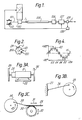
- a stranded steel strength member 101 is pulled from a drum 110 through an extruder head 102 which deposits around the strength member a core 200 of thermoplastics material such as polypropylene, the extruder head 102 being equipped with tooling to produce a multi-grooved plastics section, for example as shown in Figure 2.
- the core is formed with six such grooves 2 with square sides, for accommodating optical fibre ribbons 120, or individual fibres (not shown), one or more in each groove 2.
- the grooves could be wider, as shown at 2A in Figure 2.
- the grooves 2 are made to twist relative to the central strength member 101, in a manner to be described below with reference to Figures 3 and 4.
- the core assembly comprising the plastics core section 200 with the embedded strength member 101, is then passed through a cooling trough 105 of a length sufficient to harden the thermoplastics material, and is subsequently passed through a dryer 106 to remove water.
- the core assembly 101, 200 then passes to a capstan 107 which is arranged to draw the assembly from the extruder head 102, and whose speed is linked to that of the extruder scroll, both being controlled by a control unit 108 in response to signals from a diameter sensing device 109.
- Figure 4 is a graph of the twist angle of the groove, i.e. the angle of rotation about the core axis. This variation is represented by the continuous line 42, which can also be viewed as a representation of the groove as it would appear if the surface of the core were opened out flat.
- a twist angle of 135° is equivalent in terms of peripheral distance around the core to (135/360) ⁇ D, where D is the core diameter.
- the twisting pattern 42 is equivalent to a periodically reversing helix 41 of long pitch (i.e. 1000 mm) and large amplitude (a peak-to-peak variation of about 300°), superimposed on which is a substantially sinusoidal variation of short pitch (about 200 mm) and small amplitude (with a peak-to-peak variation of approximately 90°).
- long pitch 1000 mm
- large amplitude peak-to-peak variation 135° superimposed on which is a short pitch (100 mm) small amplitude peak-to-peak variation of about 40°.
- the preferred pattern is produced by making corresponding rotary movements of a toothed element of the extrusion die 102.
- the toothed element whose shape is generally complementary to that of the cross-section of the cable core 200, is driven by a motor drive assembly shown in Figure 3, such that its angular position varies in accordance with the curve 42 of Figure 4.
- the sequence of angular movements imparted to the toothed element would be, in one example; -65°, +132°, -65°, +132°, etc.
- the toothed element would undergo a net rotation of +67° for each cycle of this short-pitch variation, and these net rotations would accumulate to constitute the long-pitch variation.
- This sequence would be reversed at each half cycle of the long-pitch variation, i.e. after every 500 mm in axial position, and the next sequence would be; -132°, +65°, -132°, +65°, etc.
- This motion could be imparted to the toothed element of the die 102 by means of an electrically-controlled stepper motor, for example, but a particularly simple mechanical method will now be described with reference to Figure 3.
- An electric drive motor 21 is supported for periodic sliding movement about its axis on a base 22.
- the rotor of the motor 21 is coupled to a fly-wheel 24 to which the rack 29 of a rack and pinion arrangement 29, 30 is coupled eccentrically by means of a pivoting arm 28.
- the resulting reciprocating motion 31 of the rack 29 is converted to angular variations 32 of the pinion 30, which is coupled rotationally to the toothed element of the die 102.
- the rotor of the motor 21 is also coupled, by way of reduction gearing 25, to a further fly-wheel 23 which is coupled eccentrically to a fixed bracket 27 by way of a pivoting arm 26.
- the reaction from the reduction gearing 25 originating from the fixed bracket 27 causes the stator of the motor 21 to reciprocate angularly about its axis, sliding on the base 22. This superimposes an angular reciprocating motion of a relatively long period onto the relatively rapid rotational movement of fly-wheel 24.
- the motion of the pinion 30 can be made to correspond to the variation 42 of Figure 4.
- the diameter D of the core 3 is 9 mm, and the slots are 1.5 mm deep and 2 mm wide.
- the relatively long pitch although illustrated here as being 1000 mm, could for example be 800 or 900 mm, or even as much as 1200 mm or more.
- the short pitch twist angle in this example 90°, could be as little as 35° or 40°.
- the amplitude of the long pitch twist, in this example 150° could of course vary over a wide range.
- optical cable described in this example is particularly compact, the outer diameter of the sheath being as little as 13 mm or even 12.5 mm.
- twist variations are regular and periodic, it will be appreciated that the invention could still be performed using irregular variations, provided that they comprised relatively short-pitch, small amplitude variations superimposed on a relatively long-pitch variation.
- the cable core 1 is paid off the stationary supply reel 3 and is fed along a straight feed path, which may be horizontal or vertical, to a take-up reel 17.
- the core 1 is tensioned between two twin-wheel tension units 4 and 14 between which 24 optical fibre ribbons are fed into the core, 4 in each groove 2.
- the cable is tensioned so as to elongate the core by a predetermined amount sufficient to provide an overfeed of optical fibre ribbon in each groove once the core is allowed to relax further downstream.
- the core 1 passes through a grease applicator 15, at which the grooves are filled with grease, and then a lapping head 16 at which one or more tapes are applied longitudinally or helically around the core and ribbons.
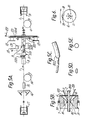
- the core 1 Downstream of the first tension unit 4, the core 1 is fed axially through an upstream fibre guide 5, a downstream fibre guide 51 and then a whipping head 9.
- the upstream fibre guide 5 guides six groups each of four parallel optical fibre ribbons from supply bobbins 12 to corresponding apertures 10 in the downstream fibre guide 51, shown in greater detail in Figure 5B.
- the rotational position of the upstream fibre guide 5 is controlled by an electric motor 13 in accordance with a servo mechanism 131, which responds to the relative angles of the upstream and downstream guides, which have shaft encoders.
- the downstream fibre guide 51 is free to rotate about the core feed path independently of the upstream fibre guide 5.
- the downstream fibre guide 51 consists of a cylindrical body 7 supported by roller bearings 511 for free rotation about the feed path, limited only by a friction brake 522 ( Figure 5A) which exerts a predetermined constant braking torque.
- the cylindrical body 7 is closed at its upstream end by a guide plate 6 in which the apertures 10, referred to above, are spaced equi-angularly at a common radius, as shown more clearly in Figure 6.
- the guide plate 6 has a central circular aperture on the core feed path, into which project six follower teeth 11 adjacent respective apertures 10.
- the teeth 11 are complementary in shape to the grooves 2, and in use follow the grooves to maintain the plate 6 and consequently the whole of the downstream fibre guide 51 in correct register with the grooves on the core 200.
- the cylindrical body 7 is fitted with a close-fitting die 8 which defines an annular guiding surface 81 concentric with, and at a slightly greater radius than, the core surface.
- a resiliently deformable O-ring 82 projects from an annular retaining groove in the surface 81.
- the die 8, cylindrical body 7 and end guide plate 6 together define a frusto-conical chamber within which the six groups of four optical fibre ribbons 120 are guided as stacks into their respective grooves 2.
- the die 8 causes a respective stack of four ribbons 120 to slide into the base of its respective groove.
- the die has a resiliently expandable bore, by virtue of the O-ring 82.
- the fact that the downstream fibre guide 51 follows precisely the positions of the grooves ensures that the ribbons 120 are guided into the grooves at the correct angle, which will in general be a small acute angle to an imaginary longitudinal line on the core surface when viewed normally to that surface. This is to allow for the fact that the grooves are helical and not straight.
- the surface 81 of the die 8 is as close as possible to the guide plate 6 without making the angle a between the ribbon 120 and the core feed path so great as to interfere with the smooth sliding of the ribbon into the groove. Over this small axial distance, the angular position of each groove will have changed very slightly, as described below.
- the upstream fibre guide will now be described with reference to Figures 5A, 5C, 5D and 5E.
- It comprises a dumb-bell shaped bobbin 501 driven by the electric motor 13 under the control of the servo mechanism described above.
- a plastics guide tube 502 is secured generally longitudinally between the peripheral edges of the two end discs of the dumb-bell shaped bobbin 501.
- the guide tubes 502 are distributed around the periphery in six groups of four adjacent ones, the groups being spaced equally by 60° to correspond with the positions of the grooves 2 and the apertures 10.
- the guide tubes 502 are co-extensive with the bobbin 501, and have a circular cross-section (Figure 5E) at the upstream end changing smoothly to an oval, almost rectangular, cross-section ( Figure 5D) at the downstream end. This is achieved by pushing the downstream ends into longitudinal grooves in the surface of the downstream disc of the bobbin 501, the tubes 502 being naturally cylindrical.
- the downstream ends of the guide tubes 502 may be inclined at a small acute angle to the axis, to assist in the passage of the ribbons into the grooves.
- An independently rotatable cylinder 503 is located directly upstream of the bobbin 501, and has a highly polished, low friction surface.
- the cylinder may be freely rotatable, but is preferably driven by independent drive means in such a direction as to assist the motion of the ribbons.
- Twenty-four ribbon supply bobbins 12 are arranged in a floating carriage 121 around the cylinder 503 and coaxial with it, with the axes of bobbins 12 parallel to that of the cylinder 503.
- the optical fibre ribbons 120 are fed from the respective bobbins 12 around respective guide rollers 504 and then around the common cylinder 503, and then through respective guide tubes 502, at each stage the angle of the ribbon axis relative to the cable core axis getting smaller, and the angle of orientation of the plane of each ribbon turning from being normal to the radius of the core to being parallel with the radius, i.e. "vertically" disposed with respect to the slots 2 as shown in Figure 2.
- This turning of the ribbons is achieved firstly by the curvature of the guide tube axes, and secondly by the flattened cross-section of the guide tubes which prevents the ribbons turning.
- the respective ribbons are maintained in station and are prevented from tangling; variations in longitudinal movement are also accommodated, and a slight tension may be applied.
- the orientation of the ribbons as they emerge from the upstream guide is thus radial relative to the core, i.e. the ribbon planes are normal to the core surface. It is at this orientation that the ribbons 120 rest in the grooves 2, side by side in a stack of four.
- the axial distance which should be less than a quarter of the pitch of the long pitch variations in groove position, between the plate 6 and the point of entry of each fibre ribbon into the groove, allows the fibre ribbon to enter at the correct angle.
- the function of the brake 522 is to cause the core 1 to twist about its axis, so that the grooves are partially straightened in the region at which the fibre ribbons are fed into them. This reduces the angular movement required of the upstream and downstream fibre guides 5, 51, and correspondingly reduces the dynamic forces involved.
- the braking force is adjusted so that the short pitch angular variations of the grooves do not overcome the brake and do not cause the fibre guides to move, so that the grooves are partially untwisted. Only the longer pitch, "S-Z" variations cause the plate 6 to apply sufficient torque to overcome the brake and to allow the fibre guides to follow the grooves.
- the amplitude of the long-pitch variations in groove angular position is ⁇ 360°, and periodically there may be an extra half-turn or full-turn.
- This is accommodated by a partial rotation of the ribbon supply bobbin carriage 121 about the core feedpath, controlled by a servo mechanism responsive to angular movements of the plate 6 in excess of a predetermined threshold, such as ⁇ 360° relative to the carriage.
- a lug 18 on the plate 6 (see Figure 2) activates either of two microswitches 19 in these circumstances, and this energises a motor 122 in the appropriate rotational sense.
- This invention is particularly useful with high fibre density cables, in which a "ribbon pack" occupies a high proportion of the groove area, and where it could be very difficult to feed the ribbons using guide tubes of the type disclosed in GB-2022644, for example.
- the invention exploits the inherent stiffness of the optical fibre ribbon, in that the end of the ribbon, downstream of the aperture in the downstream guide, need not be guided positively by a tube or any member projecting into the groove.
- the groove configuration is of the reversing helical type with superimposed short-pitch and long-pitch variations of twist angle
- the apparatus could be used with conventional reversing helical grooves, continuous helical grooves, or even straight grooves.
- the grooves are of the continuous helical type, as described above, the whole apparatus illustrated in Figure 5 would have to be rotatable.
- the ribbons are contained vertically in the grooves, i.e. edge on, with their planes radial to the cylindrical core and normal to the core surface.
- the ribbons undulate across the groove between the groove walls, and this allows a substantial degree of ribbon overfeed to be accommodated, to provide axial tensile strain relief.
- the grooves should not be so wide as to allow the ribbons to re-orientate parallel to the core surface - they should be maintained substantially "edge on”.
- the ribbon edge may engage the base of the groove, but this is not essential.
Landscapes
- Physics & Mathematics (AREA)
- Engineering & Computer Science (AREA)
- Manufacturing & Machinery (AREA)
- General Physics & Mathematics (AREA)
- Optics & Photonics (AREA)
- Processes Specially Adapted For Manufacturing Cables (AREA)
- Guides For Winding Or Rewinding, Or Guides For Filamentary Materials (AREA)
- Extrusion Moulding Of Plastics Or The Like (AREA)
Applications Claiming Priority (4)
| Application Number | Priority Date | Filing Date | Title |
|---|---|---|---|
| GB8820941 | 1988-09-07 | ||
| GB888820941A GB8820941D0 (en) | 1988-09-07 | 1988-09-07 | Cable core formed with twisting channel |
| GB8911533 | 1989-05-19 | ||
| GB898911533A GB8911533D0 (en) | 1988-09-07 | 1989-05-19 | Laying optical fibre into grooved cable core |
Publications (2)
| Publication Number | Publication Date |
|---|---|
| EP0359420A2 true EP0359420A2 (fr) | 1990-03-21 |
| EP0359420A3 EP0359420A3 (fr) | 1991-08-28 |
Family
ID=26294354
Family Applications (1)
| Application Number | Title | Priority Date | Filing Date |
|---|---|---|---|
| EP19890308533 Withdrawn EP0359420A3 (fr) | 1988-09-07 | 1989-08-23 | Ame d'un câble à rainure hélicoidale et des dispositifs d'installation pour une fibre optique dans la rainure |
Country Status (3)
| Country | Link |
|---|---|
| US (1) | US5060467A (fr) |
| EP (1) | EP0359420A3 (fr) |
| GB (2) | GB2222699B (fr) |
Cited By (1)
| Publication number | Priority date | Publication date | Assignee | Title |
|---|---|---|---|---|
| EP2356503B1 (fr) * | 2008-10-15 | 2016-08-10 | CCS Technology Inc. | Câble optique |
Families Citing this family (13)
| Publication number | Priority date | Publication date | Assignee | Title |
|---|---|---|---|---|
| DE4013755C2 (de) * | 1990-04-28 | 1995-02-16 | Kabelmetal Electro Gmbh | Optisches Verkabelungselement sowie Verfahren und Vorrichtung zu dessen Herstellung |
| DE69214115T2 (de) * | 1992-01-02 | 1997-02-06 | Yoshida Kogyo Kk | Vorrichtung zur Herstellung optischer Kabel mit Führungsnuten |
| US5263309A (en) * | 1992-05-11 | 1993-11-23 | Southwire Company | Method of and apparatus for balancing the load of a cabling apparatus |
| US5706642A (en) * | 1996-10-08 | 1998-01-13 | Haselwander; Jack G. | Variable twist level yarn |
| JP3365285B2 (ja) * | 1996-12-19 | 2003-01-08 | 住友電気工業株式会社 | Szスロット型光ファイバケーブルの製造方法及び装置 |
| US5983617A (en) * | 1997-12-31 | 1999-11-16 | Siecor Corporation | Stranding machine for use in the manufacture of fiber optic cables |
| US7299615B2 (en) * | 2004-06-18 | 2007-11-27 | Mannington Mills, Inc. | Variable twist level yarn using fluid twisting |
| US7288306B2 (en) * | 2004-08-25 | 2007-10-30 | Mannington Mills, Inc. | Textile substrate having low variable twist yarn |
| US8224140B2 (en) | 2009-12-11 | 2012-07-17 | Corning Cable Systems Llc | Cables with bend insensitive optical fibers |
| JP6990959B2 (ja) * | 2017-11-30 | 2022-01-12 | Nittoku株式会社 | 撚り線装置及び撚り線の製造方法 |
| JP2020067586A (ja) * | 2018-10-25 | 2020-04-30 | 住友電気工業株式会社 | 光ファイバケーブルの製造方法 |
| JP7810174B2 (ja) * | 2021-04-22 | 2026-02-03 | 住友電気工業株式会社 | 光ファイバの製造装置、光ファイバの製造方法 |
| CN114368642B (zh) * | 2021-11-08 | 2024-03-01 | 江苏亨通电力智网科技有限公司 | 一种光纤束主动绕纱装置及绕纱方法 |
Family Cites Families (19)
| Publication number | Priority date | Publication date | Assignee | Title |
|---|---|---|---|---|
| FR2388931A1 (fr) * | 1977-04-27 | 1978-11-24 | Lignes Telegraph Telephon | Procede de fabrication d'elements de cablage comportant des fibres optiques par machine verticale |
| GB2022644B (en) * | 1978-06-07 | 1983-03-16 | Northern Telecom Ltd | Optical cable manufacute |
| US4154049A (en) * | 1978-06-08 | 1979-05-15 | Northern Telecom Limited | Method and apparatus for forming optical cables |
| FR2458086A2 (fr) * | 1979-05-30 | 1980-12-26 | Lignes Telegraph Telephon | Perfectionnements a la fabrication d'elements de cablage comportant des fibres optiques |
| FR2500174A1 (fr) * | 1981-02-17 | 1982-08-20 | Lignes Telegraph Telephon | Tete de pose simultanee de fibres optiques dans un support cylindrique rainure et dispositif de fabrication d'elements de cablage comportant une telle tete |
| FR2502346A1 (fr) * | 1981-03-20 | 1982-09-24 | Cables De Lyon Geoffroy Delore | Dispositif suiveur de pas de rainures helicoidales |
| IT1152225B (it) * | 1982-05-31 | 1986-12-31 | Pirelli Cavi Spa | Apparecchiatura per la fabbricazione di un cavo con fibre ottiche |
| FR2565360B1 (fr) * | 1984-05-30 | 1986-09-05 | Telecommunications Sa | Systeme d'asservissement de la rotation d'un dispositif d'alimentation et de distribution de fibres optiques dans une ligne de cablage |
| DE3508959A1 (de) * | 1984-09-20 | 1986-03-27 | Frisch Kabel- Und Verseilmaschinenbau Gmbh, 4030 Ratingen | Verfahren zur herstellung eines optischen kabels |
| FR2577051B1 (fr) * | 1985-02-07 | 1989-03-31 | Lignes Telegraph Telephon | Dispositif de fabrication d'elements de cablage et tete de pose simultanee de fibres optiques dans un support cylindrique rainure pour un tel dispositif |
| FR2588095B1 (fr) * | 1985-10-01 | 1988-12-02 | Lignes Telegraph Telephon | Tete de pose de fibres optiques dans les rainures a pas alterne d'un jonc cylindrique |
| GB2181090B (en) * | 1985-10-02 | 1990-04-18 | Telephone Cables Ltd | Optical fibre cable |
| GB2186520A (en) * | 1986-02-07 | 1987-08-19 | Austral Standard Cables Pty Lt | Manufacture of helically grooved optical cable core |
| US4695128A (en) * | 1986-03-25 | 1987-09-22 | Siecor Corporation | Fiber optic cable |
| CH678232A5 (fr) * | 1986-07-03 | 1991-08-15 | Maillefer Sa | |
| US4706449A (en) * | 1986-11-21 | 1987-11-17 | Northern Telecom Limited | Apparatus for assembling optical fibers onto a support filament |
| JPS63197908A (ja) * | 1987-02-10 | 1988-08-16 | Sumitomo Electric Ind Ltd | 光フアイバケ−ブルの製造方法 |
| FR2611924B1 (fr) * | 1987-03-02 | 1989-06-09 | Telecommunications Sa | Dispositif d'introduction de fibres optiques dans des rainures helicoidales d'un jonc pour ligne de cablage |
| JPH0672971B2 (ja) * | 1987-11-20 | 1994-09-14 | 住友電気工業株式会社 | らせん溝付スペーサへの光フアイバ挿入方法 |
-
1989
- 1989-08-23 EP EP19890308533 patent/EP0359420A3/fr not_active Withdrawn
- 1989-08-29 US US07/400,829 patent/US5060467A/en not_active Expired - Fee Related
- 1989-09-06 GB GB8920098A patent/GB2222699B/en not_active Expired - Fee Related
-
1990
- 1990-01-26 GB GB9001798A patent/GB2229461B/en not_active Expired - Fee Related
Cited By (1)
| Publication number | Priority date | Publication date | Assignee | Title |
|---|---|---|---|---|
| EP2356503B1 (fr) * | 2008-10-15 | 2016-08-10 | CCS Technology Inc. | Câble optique |
Also Published As
| Publication number | Publication date |
|---|---|
| GB2222699A (en) | 1990-03-14 |
| GB2229461B (en) | 1992-11-18 |
| GB2222699B (en) | 1992-11-18 |
| GB2229461A (en) | 1990-09-26 |
| EP0359420A3 (fr) | 1991-08-28 |
| GB9001798D0 (en) | 1990-03-28 |
| GB8920098D0 (en) | 1989-10-18 |
| US5060467A (en) | 1991-10-29 |
Similar Documents
| Publication | Publication Date | Title |
|---|---|---|
| US5060467A (en) | Cable core with a twisting channel, and laying optical fiber therein | |
| US4154049A (en) | Method and apparatus for forming optical cables | |
| CA1093877A (fr) | Traduction non-disponible | |
| US4195468A (en) | Method and apparatus for use in the assembly of optical cables | |
| US4904321A (en) | Manufacture of a flexible core for an optical cable | |
| EP0521503B1 (fr) | Méthode et appareil de fabrication d'un câble de fibres optiques | |
| WO1999054542A3 (fr) | Appareil permettant l'assemblage helicoidal d'au moins deux filaments | |
| JP2871745B2 (ja) | 光ケーブルを製造する方法並びに装置 | |
| EP0171841B1 (fr) | Méthode de fabrication pour un câble optique et dispositif pour effectuer la méthode | |
| US5699660A (en) | Stranding station for reverse lay or SZ type stranding machine | |
| US4586327A (en) | SZ stranding method and apparatus | |
| GB1573331A (en) | Methods of and apparatuses for producing multiple core power current cables or conductors | |
| US6190583B1 (en) | Apparatus and method for making slotted rod for optical cable | |
| EP0336738B1 (fr) | Fabrication d'un tube flexible, avec circonférence rigide pour un câble optique | |
| CA1083393A (fr) | Cables porteurs en fibres optiques | |
| US4783953A (en) | Laying of a tube containing transmission elements onto a support filament | |
| GB2219063A (en) | Method and apparatus for manufacture of an umbilical | |
| EP0463864B1 (fr) | Appareil pour câblage alterné et procédé de câblage | |
| EP1217408A2 (fr) | Appareil de retorsion pour fibre optiques à ruban et système de fabrication pour composants de câbles optiques | |
| US5355669A (en) | Apparatus and method for simultaneous reverse stranding and longitudinal strip winding of cables | |
| EP0189304A2 (fr) | Fabrication de fibres optiques | |
| GB2064808A (en) | Process and apparatus for the production of optical fibre cables | |
| GB2056336A (en) | Apparatus and method for producing a continuous flexible tubular conduit | |
| US3732680A (en) | Wire guide for a cabling machine | |
| CA1096566A (fr) | No translaton available |
Legal Events
| Date | Code | Title | Description |
|---|---|---|---|
| PUAI | Public reference made under article 153(3) epc to a published international application that has entered the european phase |
Free format text: ORIGINAL CODE: 0009012 |
|
| AK | Designated contracting states |
Kind code of ref document: A2 Designated state(s): DE FR IT NL SE |
|
| PUAL | Search report despatched |
Free format text: ORIGINAL CODE: 0009013 |
|
| AK | Designated contracting states |
Kind code of ref document: A3 Designated state(s): DE FR IT NL SE |
|
| 17P | Request for examination filed |
Effective date: 19910917 |
|
| 17Q | First examination report despatched |
Effective date: 19921130 |
|
| STAA | Information on the status of an ep patent application or granted ep patent |
Free format text: STATUS: THE APPLICATION IS DEEMED TO BE WITHDRAWN |
|
| 18D | Application deemed to be withdrawn |
Effective date: 19930414 |