EP0359461B1 - Elément optique et système - Google Patents
Elément optique et système Download PDFInfo
- Publication number
- EP0359461B1 EP0359461B1 EP89308991A EP89308991A EP0359461B1 EP 0359461 B1 EP0359461 B1 EP 0359461B1 EP 89308991 A EP89308991 A EP 89308991A EP 89308991 A EP89308991 A EP 89308991A EP 0359461 B1 EP0359461 B1 EP 0359461B1
- Authority
- EP
- European Patent Office
- Prior art keywords
- light
- optical element
- optical
- polarised
- dichroic
- Prior art date
- Legal status (The legal status is an assumption and is not a legal conclusion. Google has not performed a legal analysis and makes no representation as to the accuracy of the status listed.)
- Expired - Lifetime
Links
Images





Classifications
-
- G—PHYSICS
- G02—OPTICS
- G02B—OPTICAL ELEMENTS, SYSTEMS OR APPARATUS
- G02B27/00—Optical systems or apparatus not provided for by any of the groups G02B1/00 - G02B26/00, G02B30/00
- G02B27/10—Beam splitting or combining systems
- G02B27/1006—Beam splitting or combining systems for splitting or combining different wavelengths
- G02B27/102—Beam splitting or combining systems for splitting or combining different wavelengths for generating a colour image from monochromatic image signal sources
- G02B27/1046—Beam splitting or combining systems for splitting or combining different wavelengths for generating a colour image from monochromatic image signal sources for use with transmissive spatial light modulators
-
- G—PHYSICS
- G02—OPTICS
- G02B—OPTICAL ELEMENTS, SYSTEMS OR APPARATUS
- G02B27/00—Optical systems or apparatus not provided for by any of the groups G02B1/00 - G02B26/00, G02B30/00
- G02B27/10—Beam splitting or combining systems
- G02B27/14—Beam splitting or combining systems operating by reflection only
-
- G—PHYSICS
- G02—OPTICS
- G02B—OPTICAL ELEMENTS, SYSTEMS OR APPARATUS
- G02B27/00—Optical systems or apparatus not provided for by any of the groups G02B1/00 - G02B26/00, G02B30/00
- G02B27/10—Beam splitting or combining systems
- G02B27/14—Beam splitting or combining systems operating by reflection only
- G02B27/149—Beam splitting or combining systems operating by reflection only using crossed beamsplitting surfaces, e.g. cross-dichroic cubes or X-cubes
-
- G—PHYSICS
- G02—OPTICS
- G02B—OPTICAL ELEMENTS, SYSTEMS OR APPARATUS
- G02B27/00—Optical systems or apparatus not provided for by any of the groups G02B1/00 - G02B26/00, G02B30/00
- G02B27/28—Optical systems or apparatus not provided for by any of the groups G02B1/00 - G02B26/00, G02B30/00 for polarising
- G02B27/283—Optical systems or apparatus not provided for by any of the groups G02B1/00 - G02B26/00, G02B30/00 for polarising used for beam splitting or combining
Definitions
- the present invention relates to an optical element, and to an optical system preferably but not necessarily incorporating such an element.
- the dichroic elements within such systems merely serve to separate the light in a passive manner, and no variation of the colour separation properties is possible.
- a projection system is also known from SID '86 Digest, page 375 (1986).
- white light from a light source is separated into light of respective colours, and the coloured light is modulated to create an image by means of light valves.
- the modulated light is then synthesised for projection.
- coloured light in this instance red, green and blue
- a first wavelength selective optical element having wavelength selection properties as shown in Figure 10 (a).
- Light of the selected colours is synthesised by a further optical element having the same wavelength selection properties. Since the light passes through such a double wavelength selection process, loss of light having wavelengths in the skirt regions of the wavelength selection curves in Figure 10 (a) is substantial.
- Figure 10 (b) shows the spectral intensity after the light has undergone synthesis. The loss of light can be seen to be about fifty percent, comparing the light intensity of Figure 10 (a) with the light intensity of Figure 10 (b). Consequently, the rate of utilisation of the light flux in the projection system is low and a high power light source is required.
- an optical element having a first dichroic layer on one surface thereof and a second dichroic layer on another surface thereof for wavelength selection of reflected light and transmitted light, wherein:
- the present invention also provides an optical system comprising a first optical element for separating light from a light source into light of respective colours, light valves for modulating the coloured light, and a second optical element for synthesising the modulated coloured light, wherein one of the first and second optical elements selectively reflects red and blue light, characterised in that the other of the first and second optical elements is an optical element according to the immediately preceding paragraph.
- the two dichroic layers cross one another at right angles. This may conveniently be achieved by forming the optical element from four right angled prisms adhered together and by coating each dichroic layer on selected surfaces of the prisms.
- the present invention also provides an optical system comprising a first optical element for separating light from alight source into light of respective colours, light valves for modulating the coloured light, and a second optical light, where one of the first and second optical elements selectively reflects red and blue light, characterised in that the other of the first and second optical element is an optical element according to the immediately preceding paragraph.
- At least one of the first and second optical elements may have polarisation-dependent wave-length selection properties.
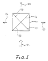
- an optical element according to the present invention comprises four right angled prisms 101 adhered together and having dichroic layers 102, 103 coated on selected ones of their right angled plane surfaces, which are sandwiched together, to provide intersecting wavelength selective layers as shown.
- the dichroic layer 102 functions as a red light (R) reflective layer with respect to P-polarised light and as a yellow light (Y) reflective layer with respect to S-polarised light.
- the dichroic layer 103 functions as a blue light (B) reflective layer with respect to the P-polarised light and as a cyan light (C) reflective layer with respect to the S-polarised light.
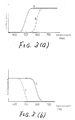
- Figures 3 (a) and 3 (b) show the wavelength selection properties, Figure 3 (a) corresponding to the dichroic layer 102, and Figure 3 (b) corresponding to the dichroic layer 103.
- the dotted line represents the wavelength selection with respect to the P-polarised light
- the solid line represents the wavelength selection with respect to the S-polarised light.
- transition or skirt regions for the wavelength selection in each case are in the visible range of light from 400 nm to 700 nm, and the wavelength selection functions for the S-polarised light effectively do not overlap those for the P-polarised light.
- the polarisation of the light determines its separation into reflected light 106, 107 and transmitted light 105.
- the linearly polarised light which is parallel to the paper surface, enters the optical element, the linearly polarised light is P-polarised light with respect to the dichroic layers, and so the dichroic layers reflect red and blue light.
- the light 105 transmitted by the element is green
- the light 106 reflected by the element is blue
- the light 107 reflected by the element is red.
- the reflected light 106 is blue close to cyan, the reflected light 107 is yellow close to red, and hardly any transmitted light 105 emerges from the optical element.
- the separation properties can be determined by the polarisation of the incident light. This means that the colour of the light produced can be controlled by electrically controlling the polarisation of the incident light by means of electro-optical effects, etc.
- Figure 2 shows how the structure of the optical element of Figure 1 may be produced.
- the dichroic layers are coated on selected ones of the surfaces, which meet in a right angle, of the respective prisms 201.
- One alternative is for the first and second dichroic layers to be coated on the surfaces designated 202 and 203, respectively.
- the other alternative is for the first and second dichroic layers to be coated on the surfaces designated 204 and 205, respectively.
- the dichroic layers in each case may be prepared in the normal manner for producing an optical thin film. In both cases, two complex dichroic layers are combined.
- a single dichroic layer may simply be coated on the longest side of one right angled prism, and this longest side may be adhered to the longest side of another right angled prism.
- the selective wavelength can still be determined by the incident polarised light.
- a P-type colour separation prism can produce wavelength selection properties for reflected and transmitted light having polarisation dependency in the same manner.
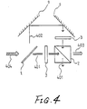
- Figure 4 shows an optical system for separating multiple, in this instance four, colours.
- the incident light is projected by way of a first and a second optical element without undergoing adverse double wavelength selection effects.
- the optical system shown in Figure 4 has as main structural elements a first optical element 1, a second optical element 2, light valves 3 and reflective mirrors 9.
- Light 404 from a light source is separated by the first optical element into transmitted light 401 and reflected light 402.
- the transmitted light 401 and the reflected light 402 are modulated by the light valves 3 before striking the second optical element 2.
- Figure 5 (a) shows the wavelength selection properties of he first optical element 1.
- the reference numeral 503 represents the transmitted light
- the reference numeral 506 represents the reflected light.
- the reference numeral 501 indicates the area where the two transition regions of the wavelength selection functions occur.
- Figure 5 (b) shows the wavelength selection properties of the second optical element.
- the reference numeral 504 represents the transmitted light and the reference numeral 507 represents the reflected light.
- the reference numeral 502 indicates the area where the transition regions of the wavelength selection functions occur. As can be seen, the area 501 does not overlap the area 502. As a result, the light 403 output after synthesis has a spectrum as shown in Figure 5 (c). Since such light is not doubly affected by the same wavelength selection properties, the reduction in light intensity as shown by Figures 10 (a) and 10 (b) is avoided.
- the light produced is magenta being synthesised from blue and red.
- the light valves 3 are provided between the first optical element and the second optical element as shown and the image is modulated, a multi-colour display can be achieved.
- the optical element 1 is preferably of conventional structure, and the optical element 2 preferably has a structure as described with reference to Figure 1. However, either of the first and second optical elements may have wavelength selection properties and dichroic layers as described in relation to Figure 1.
- a projection system as shown in Figure 6 having a first optical element according to the prior art with dichroic layers for selectively reflecting red and blue light and a second optical element according to the present invention with dichroic layers for selectively reflecting yellow and cyan light can be used.
- the arrangement of the first and second optical elements may be reversed.
- the cross shape is advantageous since the optical length is then short.
- the light of each colour entering the second optical element according to the invention may be limited to a specific polarisation (e.g. S-polarised light or P-polarised light). Further, the polarisation of the light which is reflected by the second optical element and the polarisation of the light which is transmitted by the second optical element may be different. With respect to the light of each colour which is selectively reflected by the second optical element, the wavelength selection properties of the first optical element do not overlap the wavelength selection properties of the second optical element. The coloured light which is sequentially transmitted through both elements is not affected by the wavelength selection properties of the second optical element with respect to different polarised light.
- a specific polarisation e.g. S-polarised light or P-polarised light
- the polarisation of the light which is reflected by the second optical element and the polarisation of the light which is transmitted by the second optical element may be different.
- the wavelength selection properties of the first optical element do not overlap the wavelength selection properties of the second optical element.
- Figure 6 is a structural view of the projection system for providing the full colour display.
- the first optical element comprises a blue reflective dichroic mirror 1 and a red reflective dichroic mirror 1' in the shape of a cross.
- the second optical element comprises an S-polarised cyan reflective dichroic mirror 2 and an S-polarised yellow reflective dichroic mirror 2' in the shape of a cross.
- a white light source 4 supplies light to the first optical element by way of a collimating lens 5.
- Light issuing from the second optical element is directed by a projection lens 6 onto a screen 7.
- Mirrors 9 reflect blue and red light from the mirrors 1, 1' towards respective light valves 3 for image forming, using a TN mode liquid crystal matrix type panel in this example.
- a further such light valve 3 is provided between the two optical elements.
- the light from the white light source 4 is collimated by the collimating lens 5 and then enters the first optical element.
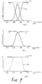
- the first optical element has colour separation properties as shown in Figure 7 (a) and divides the source light into red light (R), green light (G) and blue light (B).
- the red light (R) and blue light (B) are separated by reflection and have at least S-polarised components with respect to the dichroic mirrors of the first optical element.
- the red light (R) and blue light (B) are then reflected by the mirrors 9 and enter the light valves 3.
- the green light (G) passes directly into the respective light valve 3.
- the polarisers are arranged in Nicol's disposition.
- the light valves for modulating the red light (R) and blue light (B) transmit S-polarised light and the light valve for modulating the green light (G) transmits P-polarised light. Therefore, the red light (R) and the blue light (B) enter the second optical element as S-polarised light. The green light (G) enters the second optical element as P-polarised light.
- the second optical element comprises the S-polarised yellow reflective mirror 2 and the S-polarised cyan reflective mirror 2', and it has reflective properties as shown in Figure 7 (b) with respect to S-polarised light and transmission properties shown by the solid line in Figure 7 (c) with respect to P-polarised light. Consequently, the second optical element functions as a yellow mirror and a cyan mirror with respect only to S-polarised light, and it transmits the P-polarised light therethrough.
- the second optical element thus issues light in accordance with the functions shown in Figures 7 (a) and 7 (b) in response to incident blue light and red light, and in accordance with the functions shown in Figure 7 (a) and by the solid line 701 in Figure 7 (c) in response to incident green light.
- the blue and red light keep the wavelength properties selected by the first optical element, and the green light keeps the wavelength properties selected by the first optical element. This is due to the fact that for light of each colour, the transition region of the wavelength selection function of one optical element does not overlap the transition region of the wavelength selection function of the other optical element. In other words, light of a particular wavelength is not doubly affected by the selection.
- each of the first and the second optical elements as mentioned in this example can be realised by a dichroic element, comprising multi-layer dielectric films, which can be obtained on the market.
- a dichroic element exhibits unnecessary interference.
- alternative optical elements can be employed in the present invention.
- the second optical element exhibits constant transmission properties (see the line 701 in Figure 7 (c)).
- the second optical element may have selection properties as shown by the dotted line 702 in Figure 7 (c) with respect to green light.
- the transition regions of the wavelength selection functions of the first optical element must not overlap the transition regions of the wavelength selection functions of the second optical element.
- the transmitted light in this case green light
- the transmitted light may have a constant spectrum.
- a filter for giving the function as shown by the line 704 may be inserted into the light path between the first optical element and the second optical element to supply the colour separation of the first optical element. Then, the filter properties effectively should not overlap the transition region of the wavelength selection function of the second optical element.
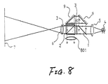
- the light from a light source 4 is collimated by a collimating lens 5 and is then separated by a first optical element 1 according to the prior art.
- the reflected component is changed in direction by mirrors 9 and then enters a light valve 3.
- the transmitted component enters a further light valve 3 directly.
- These components are synthesised by a second optical element 2.
- the synthesised light passes through a projection lens 6, thereby producing an image on a screen 7.
- the separation properties of the first optical element are shown in Figure 9 (a) and the synthesis properties of the second optical element are shown in Figure 9 (b).
- the first optical element reflects cyan light (C) and transmits yellow light (Y) in the vicinity of 550 nm of the visible spectrum.
- the second optical element reflects blue light (B) and transmits red light (R). Therefore, yellow light (Y) and cyan light (C) having a wavelength in the range of 500 nm to 550 nm emerges as leakage light towards a lens 801.
- the wavelength distribution and the maximum intensity of the synthesised light is shown in Figure 9 (c).
- transition region for the wavelength selection by the first optical element is large and the transition region for the wavelength selection by the second optical element is narrow, an excellent multi-colour display with colour purity for red, blue and black and magenta can be obtained by preventing the transition regions of the wavelength selection functions from overlapping.
- the transition region for wave-length selection by the first optical element is larger, the polarising beam splitter operates over a large area.
- the first optical element may then reflect S-polarised light and transmits P-polarised light as described.
- the second optical element operates in the same manner as the first optical element, almost no light loss occurs during transmission through the light valves, and the synthesis of the two images from the light valves is very effective.
- an effective colour projection display can be obtained by giving the wavelength selection properties to either optical element. Namely, the light is separated according to polarisation and is synthesised according to wavelength. Concretely, a polarising beam splitter for the separation of visible light is employed for the first optical element and a dichroic mirror is employed for the second optical element.
- the wavelength selection properties of an optical element can be controlled by incident polarised light.
- a compact optical element can be constructed by joining prisms in a cube.
- the present invention may be applied to various optical apparatus.
- the wavelength selection transition regions effectively do not overlap.
- polarisation properties to the wavelength selection transition region, a projection display without significant loss of light and with high efficiency can be obtained. Since one optical element may determine the colour reproduction properties, the other optical element does not need sharp selection properties.
- the focal length of the projection lens can be reduced to a minimum by disposing dichroic layers of the optical elements in the shape of a cross, whereby the design of the lens may be simplified.
Landscapes
- Physics & Mathematics (AREA)
- General Physics & Mathematics (AREA)
- Optics & Photonics (AREA)
- Projection Apparatus (AREA)
- Polarising Elements (AREA)
- Optical Filters (AREA)
- Optical Elements Other Than Lenses (AREA)
Claims (8)
- Elément optique ayant une première couche dichroïque (102) sur une de ses surfaces et une seconde couche dichroïque (103) sur une autre de ses surfaces pour la sélection de longueur d'onde de la lumière réfléchie et de la lumière émise, dans lequel :(i) la première couche dichroïque réfléchit la lumière rouge lorsque la lumière incidente subit une polarisation du type P et réfléchit la lumière jaune lorsque la lumière incidente subit une polarisation du type S ; et(ii) la seconde couche dichroïque réfléchit la lumière bleue lorsque la lumière incidente subit une polarisation du type P et réfléchit la lumière cyan lorsque la lumière incidente subit une polarisation du type S.
- Elément optique selon la revendication 1, caractérisé en ce que les deux couches dichroïques se croisent.
- Elément optique selon la revendication 1 ou 2, caractérisé en ce que l'élément comprend quatre prismes à angle droit (101, 201) joints ensemble, et en ce que la ou chaque couche dichroïque est revêtue sur au moins une surface particulière d'au moins un des prismes à angle droit.
- Système optique comprenant un premier élément optique (1) pour séparer la lumière en provenance d'une source de lumière (4) en lumière de couleurs respectives, des galvanomètres à cordes (3) pour moduler la lumière colorée, et un second élément optique (2) pour synthétiser la lumière colorée modulée, dans lequel un des premier et second éléments optiques réfléchit de manière sélective la lumière rouge et bleue, caractérisé en ce que l'autre des premier et second éléments optiques est un élément optique selon l'une quelconque des revendications 1 à 3.
- Système optique comprenant un premier élément optique (1) pour séparer la lumière en provenance d'une source de lumière (4) en lumière de couleurs respectives, des galvanomètres à cordes (3) pour moduler la lumière colorée, et un second élément optique (2) pour synthétiser la lumière colorée modulée, dans lequel un des premier et second éléments optiques réfléchit de manière sélective la lumière rouge et bleue, caractérisé en ce que l'autre des premier et second éléments optiques possède deux couches dichroïques qui réfléchissent, de manière sélective, la lumière jaune et cyan.
- Système optique selon la revendication 4, caractérisé en ce que les couches dichroïques se croisent à angle droit.
- Système optique selon les revendications 5 ou 6, caractérisé en ce que les propriétés de sélection de longueur d'onde d'au moins un des premier et second éléments optiques sont dépendantes de la polarisation.
- Projecteur comprenant une source de lumière (4), un système optique selon l'une quelconque des revendications 4 à 7, et des moyens (6) pour projeter la lumière synthétisée par le second élément optique sur un écran (7).
Applications Claiming Priority (2)
| Application Number | Priority Date | Filing Date | Title |
|---|---|---|---|
| JP227814/88 | 1988-09-12 | ||
| JP63227814A JPH0274903A (ja) | 1988-09-12 | 1988-09-12 | ダイクロイック光学素子及び投射型表示装置 |
Publications (3)
| Publication Number | Publication Date |
|---|---|
| EP0359461A2 EP0359461A2 (fr) | 1990-03-21 |
| EP0359461A3 EP0359461A3 (fr) | 1991-02-27 |
| EP0359461B1 true EP0359461B1 (fr) | 1998-11-25 |
Family
ID=16866796
Family Applications (1)
| Application Number | Title | Priority Date | Filing Date |
|---|---|---|---|
| EP89308991A Expired - Lifetime EP0359461B1 (fr) | 1988-09-12 | 1989-09-05 | Elément optique et système |
Country Status (4)
| Country | Link |
|---|---|
| US (1) | US5098183A (fr) |
| EP (1) | EP0359461B1 (fr) |
| JP (1) | JPH0274903A (fr) |
| DE (1) | DE68928858T2 (fr) |
Families Citing this family (62)
| Publication number | Priority date | Publication date | Assignee | Title |
|---|---|---|---|---|
| JPH04212102A (ja) * | 1990-07-26 | 1992-08-03 | Canon Inc | ダイクロイックミラーおよび該ミラーを用いた投写型表示装置 |
| FR2669440B1 (fr) * | 1990-11-21 | 1994-08-26 | Sextant Avionique | Dispositif de visualisation en couleur par projection mettant en óoeuvre des valves optiques. |
| US5317436A (en) * | 1990-12-31 | 1994-05-31 | Kopin Corporation | A slide assembly for projector with active matrix moveably mounted to housing |
| US5396304A (en) * | 1990-12-31 | 1995-03-07 | Kopin Corporation | Slide projector mountable light valve display |
| US5398081A (en) * | 1993-06-07 | 1995-03-14 | Raychem Corporation | Apparatus for projecting colored images |
| US5455678A (en) * | 1993-08-25 | 1995-10-03 | Kopin Corporation | Method for mounting light valves for projection display system |
| US5624174A (en) * | 1993-08-25 | 1997-04-29 | Kopin Corporation | Display panel mount for projection display system |
| US5365287A (en) * | 1993-11-08 | 1994-11-15 | Greyhawk Systems, Inc. | Three color channel, two-elevation optics for a single lens video projector |
| US5374968A (en) * | 1993-11-08 | 1994-12-20 | Greyhawk Systems, Inc. | Optics for a single-lens video projector with color-specific polarization channels |
| US5664859A (en) * | 1994-01-03 | 1997-09-09 | Kopin Corporation | Projection display docking system |
| US5550604A (en) * | 1994-06-03 | 1996-08-27 | Kopin Corporation | Compact high resolution light valve projector |
| US5806950A (en) * | 1994-06-03 | 1998-09-15 | Kopin Corporation | Compact high resolution light valve projector |
| USD368730S (en) | 1994-09-28 | 1996-04-09 | Kopin Corporation | Compact light valve projector |
| US5630659A (en) * | 1994-09-28 | 1997-05-20 | Kopin Corporation | Compact high resolution light valve projector |
| EP0752608A4 (fr) * | 1994-12-27 | 1998-01-14 | Seiko Epson Corp | Visuel du type a projection |
| JP3417757B2 (ja) * | 1995-02-28 | 2003-06-16 | ペンタックス株式会社 | 液晶表示装置およびその光束分離方法 |
| US6227670B1 (en) | 1995-03-06 | 2001-05-08 | Nikon Corporation | Projection type display apparatus |
| US6062694A (en) * | 1995-03-06 | 2000-05-16 | Nikon Corporation | Projection type display apparatus |
| JP3371190B2 (ja) * | 1996-05-24 | 2003-01-27 | ソニー株式会社 | 投射型液晶表示装置 |
| US6082863A (en) * | 1996-08-16 | 2000-07-04 | Raychem Corporation | Color projection prism |
| US6229651B1 (en) | 1996-11-01 | 2001-05-08 | Balzers Aktienresellschaft | Optical element and its manufacturing process |
| US6493159B1 (en) | 1996-11-01 | 2002-12-10 | Unaxis Balzers Aktiengesellschaft | Optical element and its manufacturing process |
| JPH10206814A (ja) * | 1997-01-23 | 1998-08-07 | Sharp Corp | 投影型カラー液晶表示装置 |
| JP3575234B2 (ja) | 1997-07-15 | 2004-10-13 | セイコーエプソン株式会社 | ダイクロイックプリズムおよび投写型表示装置 |
| JP3480256B2 (ja) | 1997-08-22 | 2003-12-15 | ミノルタ株式会社 | 投影光学装置 |
| US5951135A (en) * | 1997-10-14 | 1999-09-14 | Raychem Corporation | Color image projection system |
| US6046858A (en) * | 1997-10-16 | 2000-04-04 | Aurora Systems, Inc. | Light separation and recombination system for an off-axis projector |
| US6176586B1 (en) | 1998-03-24 | 2001-01-23 | Minolta Co., Ltd. | Projection display apparatus |
| US6097544A (en) * | 1998-03-25 | 2000-08-01 | Balzers Hochvakuum Ag | Optical element with two optical systems having identical optical paths |
| JP3959878B2 (ja) * | 1998-04-08 | 2007-08-15 | セイコーエプソン株式会社 | 光選択プリズムの製造方法 |
| TW407222B (en) * | 1998-05-14 | 2000-10-01 | Primax Electronics Ltd | The projective display apparatus used to show the image |
| US6019474A (en) * | 1998-10-06 | 2000-02-01 | International Business Machines Corporation | Modified X-cube arrangement for improved contrast projection display |
| US6375330B1 (en) | 1999-12-30 | 2002-04-23 | Gain Micro-Optics, Inc. | Reflective liquid-crystal-on-silicon projection engine architecture |
| US20020176054A1 (en) * | 1999-12-30 | 2002-11-28 | Mihalakis George M. | Reflective liquid-crystal-on-silicon projection engine architecture |
| JP3610280B2 (ja) * | 2000-04-07 | 2005-01-12 | キヤノン株式会社 | 色合成光学素子およびそれを用いた投写型画像表示装置 |
| US6808269B2 (en) * | 2002-01-16 | 2004-10-26 | Eastman Kodak Company | Projection apparatus using spatial light modulator |
| SE525114C2 (sv) * | 2002-06-24 | 2004-11-30 | Hemocue Ab | Passiv optisk komponent, samt system och metod för spektrofotometrisk analys som använder en sådan passiv optisk komponent |
| US6809873B2 (en) * | 2002-09-09 | 2004-10-26 | Eastman Kodak Company | Color illumination system for spatial light modulators using multiple double telecentric relays |
| US20060077350A1 (en) * | 2002-10-09 | 2006-04-13 | De Vaan Adrianus Johannes Step | 3-Panel transmissive projection system |
| US6947459B2 (en) * | 2002-11-25 | 2005-09-20 | Eastman Kodak Company | Organic vertical cavity laser and imaging system |
| US6758565B1 (en) | 2003-03-20 | 2004-07-06 | Eastman Kodak Company | Projection apparatus using telecentric optics |
| US6839181B1 (en) * | 2003-06-25 | 2005-01-04 | Eastman Kodak Company | Display apparatus |
| WO2005029156A1 (fr) * | 2003-09-24 | 2005-03-31 | Samsung Electronics Co., Ltd. | Filtre de couleurs et systeme de projection l'utilisant |
| US20050069376A1 (en) * | 2003-09-25 | 2005-03-31 | Eastman Kodak Company | Compound coupling |
| US7085063B2 (en) * | 2004-05-14 | 2006-08-01 | 3M Innovative Properties Company | Multi-directional optical element and an optical system utilizing the multi-directional optical element |
| WO2005114987A1 (fr) * | 2004-05-22 | 2005-12-01 | Diehl Bgt Defence Gmbh & Co. Kg | Dispositif pour detecter une scene d'objets |
| US7320521B2 (en) * | 2004-07-12 | 2008-01-22 | Next Wave Optics, Inc. | Optical engine architectures |
| US7530693B2 (en) * | 2005-05-31 | 2009-05-12 | Next Wave Optics Inc. | Single MEMS imager optical engine |
| US7411734B2 (en) | 2005-11-10 | 2008-08-12 | 3M Innovative Properties Company | Color-splitting optical element and an optical system utilizing the color-splitting optical element |
| US7158306B1 (en) | 2005-11-30 | 2007-01-02 | Corning Incorporated | Light separator |
| US10038304B2 (en) | 2009-02-17 | 2018-07-31 | Trilumina Corp. | Laser arrays for variable optical properties |
| US20130223846A1 (en) | 2009-02-17 | 2013-08-29 | Trilumina Corporation | High speed free-space optical communications |
| US10244181B2 (en) | 2009-02-17 | 2019-03-26 | Trilumina Corp. | Compact multi-zone infrared laser illuminator |
| US8995485B2 (en) | 2009-02-17 | 2015-03-31 | Trilumina Corp. | High brightness pulsed VCSEL sources |
| US8995493B2 (en) | 2009-02-17 | 2015-03-31 | Trilumina Corp. | Microlenses for multibeam arrays of optoelectronic devices for high frequency operation |
| US8979338B2 (en) | 2009-12-19 | 2015-03-17 | Trilumina Corp. | System for combining laser array outputs into a single beam carrying digital data |
| WO2011075609A1 (fr) * | 2009-12-19 | 2011-06-23 | Trilumina Corporation | Système et procédé de combinaison de réseaux de lasers pour sorties numériques |
| TWI431322B (zh) * | 2010-02-12 | 2014-03-21 | Asia Optical Co Inc | 三色光合成裝置 |
| US11095365B2 (en) | 2011-08-26 | 2021-08-17 | Lumentum Operations Llc | Wide-angle illuminator module |
| US8988564B2 (en) | 2011-09-09 | 2015-03-24 | Apple Inc. | Digital camera with light splitter |
| WO2015050473A1 (fr) | 2013-10-03 | 2015-04-09 | Huawei Technologies Co., Ltd | Système optique pour combiner des faisceaux |
| RU2602505C1 (ru) * | 2015-10-20 | 2016-11-20 | Акционерное общество "Научно-исследовательский институт телевидения" | Способ формирования телевизионного изображения в мутных средах с преобладающим над поглощением рассеянием (варианты) и устройство для его реализации |
Family Cites Families (15)
| Publication number | Priority date | Publication date | Assignee | Title |
|---|---|---|---|---|
| US3650608A (en) * | 1969-12-23 | 1972-03-21 | Texas Instruments Inc | Method and apparatus for displaying coherent light images |
| DE2018397B2 (de) * | 1970-04-17 | 1972-07-06 | Fernseh Gmbh, 6100 Darmstadt | Strahlenteilerprismensystem fuer ein geraet der farbfernsehtechnik, insbesondere fuer eine farbfernsehkamera |
| US3961334A (en) * | 1975-08-11 | 1976-06-01 | The Singer Company | Combined laser recording and color projection system |
| US4127322A (en) * | 1975-12-05 | 1978-11-28 | Hughes Aircraft Company | High brightness full color image light valve projection system |
| US4191456A (en) * | 1979-03-08 | 1980-03-04 | Hughes Aircraft Company | Optical block for high brightness full color video projection system |
| US4461542A (en) * | 1981-12-28 | 1984-07-24 | Hughes Aircraft Company | High efficiency optical tank for three color liquid crystal light valve image projection with color selective prepolarization |
| US4464018A (en) * | 1981-12-28 | 1984-08-07 | Hughes Aircraft Company | Liquid crystal light valve image projection system with color selective prepolarization and blue mirror |
| US4500172A (en) * | 1981-12-28 | 1985-02-19 | Hughes Aircraft Company | Two color liquid crystal light valve image projection system with single prepolarizer |
| EP0083090B1 (fr) * | 1981-12-28 | 1987-09-09 | Hughes Aircraft Company | Système optique de haute efficience pour la projection tricolore d'images par des valves de lumière à cristal liquide avec prépolarisation sélective à la couleur |
| US4850685A (en) * | 1984-10-22 | 1989-07-25 | Seiko Epson Corporation | Projection-type color display device |
| GB2191057A (en) * | 1986-05-19 | 1987-12-02 | Philips Electronic Associated | Colour video display arrangement |
| EP0287034B1 (fr) * | 1987-04-14 | 1995-01-18 | Seiko Epson Corporation | Dispositif d'affichage à cristal liquide en couleurs par projection |
| US4943154A (en) * | 1988-02-25 | 1990-07-24 | Matsushita Electric Industrial Co., Ltd. | Projection display apparatus |
| NL8802517A (nl) * | 1988-10-13 | 1990-05-01 | Philips Nv | Beeldprojektie-inrichting. |
| US4911547A (en) * | 1989-06-07 | 1990-03-27 | Hughes Aircraft Company | Compact optical system for a single light valve projector using two axes of polarization |
-
1988
- 1988-09-12 JP JP63227814A patent/JPH0274903A/ja active Pending
-
1989
- 1989-09-05 DE DE68928858T patent/DE68928858T2/de not_active Expired - Lifetime
- 1989-09-05 EP EP89308991A patent/EP0359461B1/fr not_active Expired - Lifetime
- 1989-09-06 US US07/403,515 patent/US5098183A/en not_active Expired - Lifetime
Also Published As
| Publication number | Publication date |
|---|---|
| US5098183A (en) | 1992-03-24 |
| EP0359461A2 (fr) | 1990-03-21 |
| EP0359461A3 (fr) | 1991-02-27 |
| JPH0274903A (ja) | 1990-03-14 |
| DE68928858T2 (de) | 1999-04-22 |
| HK1015179A1 (en) | 1999-10-08 |
| DE68928858D1 (de) | 1999-01-07 |
Similar Documents
| Publication | Publication Date | Title |
|---|---|---|
| EP0359461B1 (fr) | Elément optique et système | |
| JP3480702B2 (ja) | 反射型光バルブ用投影表示システム | |
| US6704065B1 (en) | Optical system for producing a modulated color image | |
| US5237435A (en) | Multicolor projector employing diffraction grating type liquid crystal light modulators | |
| US5826959A (en) | Projection image display apparatus | |
| US5626408A (en) | Illumination system for a color projection device and circular polarizer suitable for use in such an illumination system, and color image projection device comprising such an illumination system and circular polarizer | |
| EP0418947B1 (fr) | Système de projection | |
| US5200843A (en) | Polarized synthesization in projection type liquid crystal displays | |
| US5446510A (en) | Image display apparatus | |
| US5267029A (en) | Image projector | |
| US5829854A (en) | Angled color dispersement and recombination prism | |
| US6561652B1 (en) | Optical assembly for reflective light valves | |
| JP4637370B2 (ja) | 変調カラー画像を形成するための光学システム | |
| HK144196A (en) | Image projection device | |
| JPH11212023A5 (fr) | ||
| US5812223A (en) | Color LCD projector with three color separating polarizing beam splitters | |
| US5235444A (en) | Image projection arrangement | |
| EP0361559B1 (fr) | Dispositif de projection d'image | |
| JP3327153B2 (ja) | 投射型表示装置 | |
| JPH1048762A (ja) | 投射型画像表示装置 | |
| US20030048421A1 (en) | Liquid crystal projector | |
| JPH07113708B2 (ja) | 投射型表示装置 | |
| HK1015179B (en) | Optical element and system | |
| JPH11308640A (ja) | 虚像結像方法及び虚像結像装置 | |
| EP0083087B1 (fr) | Système optique de haute efficience pour la projection bicolore d'images par des valves de lumière à cristal liquide avec prépolarisation sélective à la couleur |
Legal Events
| Date | Code | Title | Description |
|---|---|---|---|
| PUAI | Public reference made under article 153(3) epc to a published international application that has entered the european phase |
Free format text: ORIGINAL CODE: 0009012 |
|
| AK | Designated contracting states |
Kind code of ref document: A2 Designated state(s): DE FR GB NL |
|
| RHK1 | Main classification (correction) |
Ipc: G02B 5/28 |
|
| PUAL | Search report despatched |
Free format text: ORIGINAL CODE: 0009013 |
|
| 17P | Request for examination filed |
Effective date: 19901206 |
|
| AK | Designated contracting states |
Kind code of ref document: A3 Designated state(s): DE FR GB NL |
|
| 17Q | First examination report despatched |
Effective date: 19931203 |
|
| GRAG | Despatch of communication of intention to grant |
Free format text: ORIGINAL CODE: EPIDOS AGRA |
|
| GRAG | Despatch of communication of intention to grant |
Free format text: ORIGINAL CODE: EPIDOS AGRA |
|
| GRAH | Despatch of communication of intention to grant a patent |
Free format text: ORIGINAL CODE: EPIDOS IGRA |
|
| GRAH | Despatch of communication of intention to grant a patent |
Free format text: ORIGINAL CODE: EPIDOS IGRA |
|
| GRAA | (expected) grant |
Free format text: ORIGINAL CODE: 0009210 |
|
| AK | Designated contracting states |
Kind code of ref document: B1 Designated state(s): DE FR GB NL |
|
| REF | Corresponds to: |
Ref document number: 68928858 Country of ref document: DE Date of ref document: 19990107 |
|
| ET | Fr: translation filed | ||
| PLBE | No opposition filed within time limit |
Free format text: ORIGINAL CODE: 0009261 |
|
| STAA | Information on the status of an ep patent application or granted ep patent |
Free format text: STATUS: NO OPPOSITION FILED WITHIN TIME LIMIT |
|
| 26N | No opposition filed | ||
| REG | Reference to a national code |
Ref country code: GB Ref legal event code: IF02 |
|
| PGFP | Annual fee paid to national office [announced via postgrant information from national office to epo] |
Ref country code: NL Payment date: 20080915 Year of fee payment: 20 Ref country code: FR Payment date: 20080915 Year of fee payment: 20 |
|
| PGFP | Annual fee paid to national office [announced via postgrant information from national office to epo] |
Ref country code: GB Payment date: 20080910 Year of fee payment: 20 |
|
| PGFP | Annual fee paid to national office [announced via postgrant information from national office to epo] |
Ref country code: DE Payment date: 20080919 Year of fee payment: 20 |
|
| REG | Reference to a national code |
Ref country code: GB Ref legal event code: PE20 Expiry date: 20090904 |
|
| NLV7 | Nl: ceased due to reaching the maximum lifetime of a patent |
Effective date: 20090905 |
|
| PG25 | Lapsed in a contracting state [announced via postgrant information from national office to epo] |
Ref country code: GB Free format text: LAPSE BECAUSE OF EXPIRATION OF PROTECTION Effective date: 20090904 Ref country code: NL Free format text: LAPSE BECAUSE OF EXPIRATION OF PROTECTION Effective date: 20090905 |