EP0359498A2 - Ensemble de boîtier et de bracelet de montre destiné à être utilisé dans une montre-bracelet - Google Patents
Ensemble de boîtier et de bracelet de montre destiné à être utilisé dans une montre-bracelet Download PDFInfo
- Publication number
- EP0359498A2 EP0359498A2 EP89309188A EP89309188A EP0359498A2 EP 0359498 A2 EP0359498 A2 EP 0359498A2 EP 89309188 A EP89309188 A EP 89309188A EP 89309188 A EP89309188 A EP 89309188A EP 0359498 A2 EP0359498 A2 EP 0359498A2
- Authority
- EP
- European Patent Office
- Prior art keywords
- band
- case
- watch
- fitting
- assembly
- Prior art date
- Legal status (The legal status is an assumption and is not a legal conclusion. Google has not performed a legal analysis and makes no representation as to the accuracy of the status listed.)
- Granted
Links
Images

Classifications
-
- A—HUMAN NECESSITIES
- A44—HABERDASHERY; JEWELLERY
- A44C—PERSONAL ADORNMENTS, e.g. JEWELLERY; COINS
- A44C5/00—Bracelets; Wrist-watch straps; Fastenings for bracelets or wrist-watch straps
- A44C5/18—Fasteners for straps, chains or the like
-
- G—PHYSICS
- G04—HOROLOGY
- G04B—MECHANICALLY-DRIVEN CLOCKS OR WATCHES; MECHANICAL PARTS OF CLOCKS OR WATCHES IN GENERAL; TIME PIECES USING THE POSITION OF THE SUN, MOON OR STARS
- G04B37/00—Cases
- G04B37/14—Suspending devices, supports or stands for time-pieces insofar as they form part of the case
- G04B37/1486—Arrangements for fixing to a bracelet
Definitions
- the present invention relates to a watch case and band assembly for use in a wrist watch.
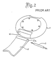
- Figure 2 shows a known watch case and band assembly for use in a wrist watch in which a recess 14 for fitting a band part 12 is formed on the reverse side of a case part 11 of a wrist watch.
- a band retaining member 13, for example a spring bar, is retained at both ends within the recess 14, the band retaining member 13 passing through a hole or bore 12a in the band part 12, thereby coupling together the band part 12 and the case part 11.
- the recess 14 provided on the reverse side of the case part 11 is open at its lower side, that is, on the reverse side of the watch, and therefore, when the watch is attached to the wrist, the band part 12 can pivot about the band retaining member 13 so as to make the connection between the case part 11 and the band part 12 unreliable.
- the end portion of the band part 12 is supported within the recess 14 on the reverse side of the case part 11, it is impossible to increase the size of an indicator-masking portion which is formed on the obverse side of the case part 11 which has the recess 14 formed therein, and this imposes a great restriction on designing.
- a watch case and band assembly for use in a wrist watch comprising a case part and a band part one part of which has at least one portion which is located in a respective space in the other part and which is connected thereat to the other part by retaining means characterised in that the or each said portion is an outwardly extending portion of the said one part and is disposed adjacent at least one recess in the said one part, the other part having at least one projecting portion which is disposed adjacent the or each space and is located in a respective recess.
- the or each outwardly extending portion is disposed between two recesses, the other part having two projecting portions on opposite sides of the respective space.
- the said one part is the case part and the said other part is the band part.
- case part is preferably provided on each of its diametrically opposite sides with an outwardly extending portion disposed between respective recesses, each of the opposite ends of the band part being provided with a respective space and projecting portions.
- the band part may have two portions one end of each of which is connected to the case part and the opposite end of which is connected to the other portion of the band part.
- the band part may have one single expansible portion only.
- the or each outwardly extending portion and the respective projecting portion or portions have aligned bores, the respective retaining means being located in said aligned bores.
- the distal end of the or each outwardly projecting portion engages or is engageable with a respective surface of the band part so as to limit pivotal movement of the latter with respect to the case part.
- pivoting of the first link of the band part is limited by the walls of the recesses.
- the engagement between the said distal end and the said surface may be arranged to limit the pivoting of the second link of the band part so as to make it look as though there is an integral coupling structure between the case part and the band part.
- FIG. 1 there is shown a watch case and band assembly according to the present invention comprising a case part 1, a band part 2 composed of a plurality of links joined together, and a retaining member 3 which is used to couple the band part 2 to the case part 1.
- the case part 1 is provided on diametrically opposite sides thereof with fitting portions 1a for coupling together the band part 2 and the case part 1.
- Each fitting portion 1a is formed with an outwardly extending portion 1e.
- the side of the outwardly extending portion 1e is provided with a bore 1c for receiving the retaining member 3 which is in the form of a bar.
- Each outwardly extending portion 1e is disposed between recesses 1b which are formed in a portion of the case part 1 which is contiguous with each end of the fitting portion 1a.
- Each outwardly extending portion 1e moreover, is disposed in a respective space 2e in the band part 2.
- the recesses 1b are, if necessary, coated with a polymeric material suitable for use with the material of the case part 1 to prevent the case part 1 from being damaged by contact with the band part 2.
- the first link 2c of the band part 2 is formed with a bore 2a which, when the parts are assembled, communicates with and is aligned the bore 1c in the case part 1.
- the distal end projecting portions 2b of the first link 2c of the band 2 that project with respect to the bore 2a are inserted into the corresponding recesses 1b formed in the case part 1, so that, when the band part 2 is attached to the wrist, the pivoting of the first link 2c of the band part 2 about the retaining member 3 and relative to the case part 1 is limited by the distal end portions 2b of the first link 2c of the band part 2 which abut against the inner walls of the corresponding recesses 1b.
- the projecting portions 2b are disposed on opposite sides of the space 2e.
- each fitting portion 1a of the case part 1 abuts against a surface 2d of the second link of the band part 2, so that the pivoting of the band part 2 relative to the watch case is limited within a certain range which is determined by the engagement between the surface 2d and the distal end 1d.
- the end portions 2b of the band 2 are inserted into recesses 1b provided on opposite sides of the outwardly extending portion 1e formed in each fitting portion 1a of the side of the case part 1 where the band part 2 is fitted, thereby limiting the pivoting of the band part 2 and, in addition, the distal end 1d of the outwardly extending portion 1e is also arranged to abut against a link of the band part 2, thereby assisting in stabilising the connection between the band part 2 and the case part 1. It is also possible with this construction to create a variety of designs.
- the construction shown in Figure 1 is thus adapted to minimize the gaps between the case part 1 and the band part 2 so that the watch case appears to be integral with its band, while at the same time being adapted to prevent excessive pivoting of the band relative to the watch case when the user wears the wrist watch.
Landscapes
- Physics & Mathematics (AREA)
- General Physics & Mathematics (AREA)
- Buckles (AREA)
- Professional, Industrial, Or Sporting Protective Garments (AREA)
- Clamps And Clips (AREA)
- Snaps, Bayonet Connections, Set Pins, And Snap Rings (AREA)
- Stackable Containers (AREA)
Applications Claiming Priority (2)
| Application Number | Priority Date | Filing Date | Title |
|---|---|---|---|
| JP119679/88 | 1988-09-12 | ||
| JP1988119679U JPH0618313Y2 (ja) | 1988-09-12 | 1988-09-12 | 時計ケースとバンドの嵌合構造 |
Publications (3)
| Publication Number | Publication Date |
|---|---|
| EP0359498A2 true EP0359498A2 (fr) | 1990-03-21 |
| EP0359498A3 EP0359498A3 (en) | 1990-05-09 |
| EP0359498B1 EP0359498B1 (fr) | 1993-04-07 |
Family
ID=14767367
Family Applications (1)
| Application Number | Title | Priority Date | Filing Date |
|---|---|---|---|
| EP89309188A Expired - Lifetime EP0359498B1 (fr) | 1988-09-12 | 1989-09-11 | Ensemble de boîtier et de bracelet de montre destiné à être utilisé dans une montre-bracelet |
Country Status (3)
| Country | Link |
|---|---|
| EP (1) | EP0359498B1 (fr) |
| JP (1) | JPH0618313Y2 (fr) |
| KR (1) | KR900004295A (fr) |
Families Citing this family (1)
| Publication number | Priority date | Publication date | Assignee | Title |
|---|---|---|---|---|
| JP2001046143A (ja) * | 1999-08-05 | 2001-02-20 | Hiroyoshi Takagi | コンパクトケース |
Family Cites Families (4)
| Publication number | Priority date | Publication date | Assignee | Title |
|---|---|---|---|---|
| US2990678A (en) * | 1956-05-22 | 1961-07-04 | Comte Jacques | Wrist-watch |
| GB933969A (en) * | 1960-10-28 | 1963-08-14 | Theodor Engelhard | Improvements in or relating to strap attachments for wristwatches |
| JPS5418939Y2 (fr) * | 1974-07-03 | 1979-07-14 | ||
| JPS61170309U (fr) * | 1985-04-12 | 1986-10-22 |
-
1988
- 1988-09-12 JP JP1988119679U patent/JPH0618313Y2/ja not_active Expired - Lifetime
-
1989
- 1989-09-11 EP EP89309188A patent/EP0359498B1/fr not_active Expired - Lifetime
- 1989-09-12 KR KR1019890013195A patent/KR900004295A/ko not_active Withdrawn
Also Published As
| Publication number | Publication date |
|---|---|
| KR900004295A (ko) | 1990-04-12 |
| JPH0241191U (fr) | 1990-03-22 |
| JPH0618313Y2 (ja) | 1994-05-11 |
| EP0359498B1 (fr) | 1993-04-07 |
| EP0359498A3 (en) | 1990-05-09 |
Similar Documents
| Publication | Publication Date | Title |
|---|---|---|
| JP3394849B2 (ja) | 紐止め具 | |
| US4935910A (en) | Fitting structure for watch case and band | |
| USD399777S (en) | Bracelet for watch | |
| USD390496S (en) | Clasp adapter | |
| US5038557A (en) | Adjustable watch band having multi-part link units | |
| USD390128S (en) | Watch and bracelet | |
| EP0787664B1 (fr) | Système d'arrêt avec ouvertures désaxées pour les tiges d'un transporteur | |
| USD401864S (en) | Watch and bracelet | |
| USD396899S (en) | Joystick | |
| WO1989001548A1 (fr) | Griffe de pelle excavatrice | |
| EP0384075A2 (fr) | Joint pivotant pour chaîne | |
| EP0841022B1 (fr) | Dispositif de fixation d'un bracelet à une montre | |
| FR2701741B1 (fr) | Joint homocinetique, notamment du type a tripode. | |
| JPH05253009A (ja) | 腕 輪 | |
| USD390129S (en) | Watch and bracelet | |
| MY124606A (en) | Multi-way input device | |
| USD399462S (en) | Pair of shock absorber ends | |
| US20020122152A1 (en) | Angle adjustment mechanism for temple of eyeglasses | |
| USD390127S (en) | Watch and bracelet | |
| EP0359498A2 (fr) | Ensemble de boîtier et de bracelet de montre destiné à être utilisé dans une montre-bracelet | |
| USD375913S (en) | Jewelry chain | |
| USD443584S1 (en) | Housing for batteries | |
| USD355663S (en) | Optical viewer | |
| EP0248529A1 (fr) | Monture de lunettes | |
| USD349661S (en) | Water meter housing |
Legal Events
| Date | Code | Title | Description |
|---|---|---|---|
| PUAI | Public reference made under article 153(3) epc to a published international application that has entered the european phase |
Free format text: ORIGINAL CODE: 0009012 |
|
| AK | Designated contracting states |
Kind code of ref document: A2 Designated state(s): CH GB IT LI |
|
| PUAL | Search report despatched |
Free format text: ORIGINAL CODE: 0009013 |
|
| AK | Designated contracting states |
Kind code of ref document: A3 Designated state(s): CH GB IT LI |
|
| 17P | Request for examination filed |
Effective date: 19900911 |
|
| 17Q | First examination report despatched |
Effective date: 19910823 |
|
| GRAA | (expected) grant |
Free format text: ORIGINAL CODE: 0009210 |
|
| AK | Designated contracting states |
Kind code of ref document: B1 Designated state(s): CH GB IT LI |
|
| ITF | It: translation for a ep patent filed | ||
| PLBE | No opposition filed within time limit |
Free format text: ORIGINAL CODE: 0009261 |
|
| STAA | Information on the status of an ep patent application or granted ep patent |
Free format text: STATUS: NO OPPOSITION FILED WITHIN TIME LIMIT |
|
| 26N | No opposition filed | ||
| PGFP | Annual fee paid to national office [announced via postgrant information from national office to epo] |
Ref country code: GB Payment date: 19940901 Year of fee payment: 6 |
|
| PGFP | Annual fee paid to national office [announced via postgrant information from national office to epo] |
Ref country code: CH Payment date: 19940914 Year of fee payment: 6 |
|
| PG25 | Lapsed in a contracting state [announced via postgrant information from national office to epo] |
Ref country code: GB Effective date: 19950911 |
|
| PG25 | Lapsed in a contracting state [announced via postgrant information from national office to epo] |
Ref country code: LI Effective date: 19950930 Ref country code: CH Effective date: 19950930 |
|
| GBPC | Gb: european patent ceased through non-payment of renewal fee |
Effective date: 19950911 |
|
| REG | Reference to a national code |
Ref country code: CH Ref legal event code: PL |
|
| PG25 | Lapsed in a contracting state [announced via postgrant information from national office to epo] |
Ref country code: IT Free format text: LAPSE BECAUSE OF NON-PAYMENT OF DUE FEES;WARNING: LAPSES OF ITALIAN PATENTS WITH EFFECTIVE DATE BEFORE 2007 MAY HAVE OCCURRED AT ANY TIME BEFORE 2007. THE CORRECT EFFECTIVE DATE MAY BE DIFFERENT FROM THE ONE RECORDED. Effective date: 20050911 |