EP0359527A2 - Buse de soufflage - Google Patents
Buse de soufflage Download PDFInfo
- Publication number
- EP0359527A2 EP0359527A2 EP89309252A EP89309252A EP0359527A2 EP 0359527 A2 EP0359527 A2 EP 0359527A2 EP 89309252 A EP89309252 A EP 89309252A EP 89309252 A EP89309252 A EP 89309252A EP 0359527 A2 EP0359527 A2 EP 0359527A2
- Authority
- EP
- European Patent Office
- Prior art keywords
- nozzle
- filament
- parts
- gas jet
- jet wiping
- Prior art date
- Legal status (The legal status is an assumption and is not a legal conclusion. Google has not performed a legal analysis and makes no representation as to the accuracy of the status listed.)
- Granted
Links
- 239000011248 coating agent Substances 0.000 claims abstract description 10
- 238000000576 coating method Methods 0.000 claims abstract description 10
- 229910052751 metal Inorganic materials 0.000 claims description 22
- 239000002184 metal Substances 0.000 claims description 22
- 238000000034 method Methods 0.000 claims description 13
- 238000001816 cooling Methods 0.000 claims description 10
- 239000012809 cooling fluid Substances 0.000 claims description 3
- 229910001338 liquidmetal Inorganic materials 0.000 claims 1
- 239000007789 gas Substances 0.000 description 55
- HCHKCACWOHOZIP-UHFFFAOYSA-N Zinc Chemical compound [Zn] HCHKCACWOHOZIP-UHFFFAOYSA-N 0.000 description 3
- 239000000463 material Substances 0.000 description 3
- 229910052725 zinc Inorganic materials 0.000 description 3
- 239000011701 zinc Substances 0.000 description 3
- 239000000956 alloy Substances 0.000 description 2
- 229910045601 alloy Inorganic materials 0.000 description 2
- 239000004411 aluminium Substances 0.000 description 2
- 229910052782 aluminium Inorganic materials 0.000 description 2
- XAGFODPZIPBFFR-UHFFFAOYSA-N aluminium Chemical compound [Al] XAGFODPZIPBFFR-UHFFFAOYSA-N 0.000 description 2
- RWSOTUBLDIXVET-UHFFFAOYSA-N Dihydrogen sulfide Chemical compound S RWSOTUBLDIXVET-UHFFFAOYSA-N 0.000 description 1
- CWYNVVGOOAEACU-UHFFFAOYSA-N Fe2+ Chemical compound [Fe+2] CWYNVVGOOAEACU-UHFFFAOYSA-N 0.000 description 1
- 229910000831 Steel Inorganic materials 0.000 description 1
- 238000010276 construction Methods 0.000 description 1
- 238000003754 machining Methods 0.000 description 1
- 150000002739 metals Chemical class 0.000 description 1
- 239000010959 steel Substances 0.000 description 1
Images

Classifications
-
- C—CHEMISTRY; METALLURGY
- C25—ELECTROLYTIC OR ELECTROPHORETIC PROCESSES; APPARATUS THEREFOR
- C25F—PROCESSES FOR THE ELECTROLYTIC REMOVAL OF MATERIALS FROM OBJECTS; APPARATUS THEREFOR
- C25F5/00—Electrolytic stripping of metallic layers or coatings
-
- C—CHEMISTRY; METALLURGY
- C23—COATING METALLIC MATERIAL; COATING MATERIAL WITH METALLIC MATERIAL; CHEMICAL SURFACE TREATMENT; DIFFUSION TREATMENT OF METALLIC MATERIAL; COATING BY VACUUM EVAPORATION, BY SPUTTERING, BY ION IMPLANTATION OR BY CHEMICAL VAPOUR DEPOSITION, IN GENERAL; INHIBITING CORROSION OF METALLIC MATERIAL OR INCRUSTATION IN GENERAL
- C23C—COATING METALLIC MATERIAL; COATING MATERIAL WITH METALLIC MATERIAL; SURFACE TREATMENT OF METALLIC MATERIAL BY DIFFUSION INTO THE SURFACE, BY CHEMICAL CONVERSION OR SUBSTITUTION; COATING BY VACUUM EVAPORATION, BY SPUTTERING, BY ION IMPLANTATION OR BY CHEMICAL VAPOUR DEPOSITION, IN GENERAL
- C23C2/00—Hot-dipping or immersion processes for applying the coating material in the molten state without affecting the shape; Apparatus therefor
- C23C2/14—Removing excess of molten coatings; Controlling or regulating the coating thickness
- C23C2/16—Removing excess of molten coatings; Controlling or regulating the coating thickness using fluids under pressure, e.g. air knives
- C23C2/18—Removing excess of molten coatings from elongated material
- C23C2/185—Tubes; Wires
Definitions
- the present invention relates to an improved process for the gas jet wiping of metallic filaments which have been dip coated in a molten metal bath, to apparatus for carrying out such a process and to an improved method for threading a filament through such an apparatus.
- gas jet wiping processes a stream of a gas is caused to impinge upon the filament to strip the excess coating material therefrom.
- Typical gas jet wiping apparatus and nozzles therefore are described in the following patent specifications: United States 2,194,565 3,060,889 3,270,364 3,611,986 3,707,400 3,736,174 4,287,238 Australian 458,892 537,944 539,396 544,277
- the present invention consists in a gas jet wiping nozzle or a reactive gas containment vessel for use in the gas jet wiping of a filament, in which the nozzle or the containment vessel is formed of at least two non-annular parts which when abutted together form an annulus, the at least two parts being separable from one another in a direction transverse to the direction in which, in use, a filament would pass through the nozzle and/or the containment vessel, means being provided to releasably retain the at least two parts in operational abutment.
- the present invention consists in apparatus for the coating of a metallic filament with a molten metal, comprising a molten metal bath, means to draw a filament from the molten metal bath and through the apparatus, a gas jet wiping nozzle through which the filament passes and cooling means adapted to cool the filament by contacting it with a cooling fluid, characterized in that the gas jet wiping nozzle is a nozzle according to the present invention and/or in that a reactive gas containment vessel according to this invention is positioned between the gas jet wiping nozzle and the cooling means.
- the present invention consists in a process for the gas jet wiping of a metallic filament passing upwardly from a molten metal bath, wherein the filament passes through a gas jet wiping nozzle and/or a reactive gas containment vessel according to this invention.
- the present invention comprises a method of threading a filament in apparatus for the coating of a metallic filament with a molten metal according to this invention, comprising the steps of:-
- the gas jet wiping nozzle used in the present invention may be of any conventional construction but is preferably constructed according to Applicant's copending Australian patent application No. PJ 0032 entitled “Improved Product and Process” the contents whereof are incorporated herein by reference.
- the essential feature of the present invention is that the nozzle and/or the reactive gas containment vessel be separable into parts such that the filament does not have to be threaded through the throat of the nozzle or the vessel but rather the nozzle or vessel parts are separated laterally while the filament is positioned in the apparatus and then brought together in operational abutment about the threaded filament.
- the nozzle may be cut diametrically into two equal parts with plane abutting faces. It is preferred, however, that means be provided on the parts to ensure that when abutting the gas passages in the respective parts of the nozzle are in alignment. In one embodiment of the invention this is done by forming a ridge on an abutting face of one part of the nozzle and a corresponding groove on the abutting face of the other part. While it is preferred that the nozzle is cut into only two parts it is recognised that the advantages of the present invention could be obtained with a nozzle cut into three or more parts.
- operation abutment is used in this specification to indicate that there is a sufficient contact between the faces that there is only a limited possibility for wiping gas to flow out of the nozzle between the abutting faces of the nozzle parts rather than through the gas passage.
- operational abutment is used in this specification to indicate that there is sufficient contact between the faces that there is only a limited possibility for reactive gas to leak from the containment vessel other than through the filament inlet and outlet apertures. It has been surprisingly found that this is quite easy to achieve by simple machining of the abutting faces and that, contrary to expectation, there is no significant gas loss in either case.
- the nozzle or containment vessel parts may be held in abutment by any suitable means. These means may comprise a simple clamp which fits about the nozzle or vessel. In an alternative embodiment spring pins are used to both align the parts and to releasably hold them together. Alternatively the parts, or at least one of them, may be mounted on a double acting hydraulic or pneumatic ram which can be actuated to move the parts, or at least one of them, relatively into or out of operational abutment. If desired one part may be fixed and the other moveable or they may both be moveable. If desired the parts may be hingedly or slidably connected together. In one particular embodiment the nozzle parts are provided with corresponding dovetailed grooves and ribs. The nozzle parts in this embodiment of the invention are initially moved apart axially of the nozzle to separate the corresponding dovetail ribs from the dovetail grooves and are then moved apart radially to allow replacement of the filament.
- filament is taken to mean wire, both circular and non-circular in cross-section, narrow strip material having a width no more than 10 times its thickness and tubular material.
- the non-circular wire may be angled in cross-section.
- the invention is most particularly applicable to the coating of wires having a diameter or maximum cross-sectional dimension of from 1 to 20 mm.
- the wire, strip or tube is preferably made of a ferrous metal such as steel.
- the present invention is particularly suitable for use in the coating of metal filaments with molten metals such as zinc, aluminium and alloys thereof.
- the apparatus is to include a reactive gas containment vessel this is preferably as described in Applicants copending Australian patent application No. PJ 0030 entitled "Further Improved Product and Process".
- the above comments in connection with the retaining means for the nozzle parts are applicable equally to the reactive gas containment vessel.
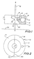
- the jet wiping nozzle 10 of Figs. 1 and 2 has an annular body 11 defining a gas inlet 12, a circular gas chamber 13 and a gas passage 14.
- the gas passage 14 opens into a circular throat 15 through which a wire 16 passes.
- the nozzle 10 is split diametrically into two body parts 17 and 18.
- the body part 17 has on its abutting face 19 a V-shaped groove 21 while the part 18 has on its abutting face 22 a corresponding V-shaped rib 23.
- Magnets (not shown) are provided in the body part 17 to hold the body parts 17 and 18 in abutment with the rib 23 rested in the groove 21 to align the gas passage 14 in the two body parts 17 and 18.
- the wire 16 is passed through a zinc coating bath 24, from which it emerges substantially vertically, through the jet wiping nozzle 10 and through cooling means (not shown) of the type shown in Australian patent specification 462,301. If the wire 16 breaks or has for some other reason to be replaced the gas flow through the nozzle 10 will be stopped, the nozzle body parts 17 and 18 manually separated, the new wire passed through the bath 24 in the conventional manner and upwardly to pass between the separated nozzle body parts 17 and 18 through the cooling means in the conventional manner. The nozzle body parts 17 and 18 may be then repositioned in operational abutment around the wire 16 and jet wiping recommenced by starting gas flow through the nozzle 10. This wire replacement has been achieved without the necessity of threading the wire 16 through the relatively small throat 15 as would normally be required.
- the gas jet wiping nozzle of Figures 3 and 4 is similar to that of Figures 1 and 2 and the same numerals have been made to identify similar parts.
- the principal differences are that the nozzle part 17 is formed with four elongate bores 24 into which fit the pins 25 on the nozzle part 19.
- the pins 25 are of a spring type having a longitudinally extending diametric slit forming a pair of parallel spring arms.
- the diameter of the pins 25 is slightly larger than the diameter of the bores 24 such that the pins 25 serve to both align the two parts of the nozzle and to hold them firmly together.
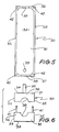
- FIGS 5 and 6 show a reactive gas containment vessel 30 comprising a pair of box-like halves 31 and 32.
- Each of the halves 31 and 32 comprises three adjacent side walls 33, 34 and 35 and end walls 36 and 37.
- Each of the end walls 36 and 37 has mid-way along its free edge a scalloped recess 38 to allow the passage of a wire to run between the two halves 31 and 32 when they are abutted.
- a reactive gas inlet pipe 39 enters the box-like half 31 through the side wall 34.
- the two halves 31 and 32 may be releasably held with the free edges of side walls 33 and 35 and end walls 36 and 37 abutting by four spring-type pins 41 which extend from half 32 into bores 42 in the half 31.
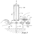
- FIG. 7 The use of a gas jet wiping nozzle 10 as shown in Figures 3 and 4 and a reactive gas containment vessel 30 is shown in Figure 7.
- the nozzle part 17 is mounted on one end of a toothed rack 43 which may be moved radially towards and away from the wire 16 by a pinion (not shown) rotated by a knob 44.
- the nozzle part 18 can be removed from nozzle part 17 manually.
- the nozzle part 17 may be then withdrawn radially away from the wire 16 by the manual operation of the knob 44.
- the reactive gas containment vessel may be similarly opened by manually drawing the half 32 away from half 31.
- the wire 16 may then be rethreaded through the apparatus and the nozzle 10 and reactive gas containment vessel 30 repositioned about the wire 16.
Landscapes
- Chemical & Material Sciences (AREA)
- Chemical Kinetics & Catalysis (AREA)
- Engineering & Computer Science (AREA)
- Materials Engineering (AREA)
- Metallurgy (AREA)
- Organic Chemistry (AREA)
- Mechanical Engineering (AREA)
- Electrochemistry (AREA)
- Coating With Molten Metal (AREA)
- Percussion Or Vibration Massage (AREA)
- Treatment Of Fiber Materials (AREA)
- Image-Pickup Tubes, Image-Amplification Tubes, And Storage Tubes (AREA)
- Glanulating (AREA)
- Application Of Or Painting With Fluid Materials (AREA)
- Automatic Analysis And Handling Materials Therefor (AREA)
- Separation Of Particles Using Liquids (AREA)
- Cleaning In General (AREA)
- Details Or Accessories Of Spraying Plant Or Apparatus (AREA)
- Fire-Detection Mechanisms (AREA)
- Heat Treatment Of Strip Materials And Filament Materials (AREA)
- Nozzles (AREA)
- Absorbent Articles And Supports Therefor (AREA)
- Paper (AREA)
- Treatments Of Macromolecular Shaped Articles (AREA)
Applications Claiming Priority (2)
| Application Number | Priority Date | Filing Date | Title |
|---|---|---|---|
| AU403/88 | 1988-09-13 | ||
| AUPJ040388 | 1988-09-13 |
Publications (3)
| Publication Number | Publication Date |
|---|---|
| EP0359527A2 true EP0359527A2 (fr) | 1990-03-21 |
| EP0359527A3 EP0359527A3 (fr) | 1991-01-30 |
| EP0359527B1 EP0359527B1 (fr) | 1996-02-21 |
Family
ID=3773367
Family Applications (1)
| Application Number | Title | Priority Date | Filing Date |
|---|---|---|---|
| EP89309252A Expired - Lifetime EP0359527B1 (fr) | 1988-09-13 | 1989-09-12 | Buse de soufflage |
Country Status (19)
| Country | Link |
|---|---|
| US (1) | US5061522A (fr) |
| EP (1) | EP0359527B1 (fr) |
| JP (1) | JP2836857B2 (fr) |
| KR (1) | KR0157614B1 (fr) |
| CN (1) | CN1024567C (fr) |
| AT (1) | ATE134392T1 (fr) |
| AU (1) | AU618839B2 (fr) |
| BR (1) | BR8904603A (fr) |
| CA (1) | CA1326354C (fr) |
| DE (1) | DE68925710T2 (fr) |
| ES (1) | ES2084601T3 (fr) |
| GR (1) | GR3019944T3 (fr) |
| IN (1) | IN175881B (fr) |
| MX (1) | MX174283B (fr) |
| MY (1) | MY104200A (fr) |
| NO (1) | NO179047C (fr) |
| NZ (1) | NZ230495A (fr) |
| PT (1) | PT91696B (fr) |
| ZA (1) | ZA896805B (fr) |
Cited By (2)
| Publication number | Priority date | Publication date | Assignee | Title |
|---|---|---|---|---|
| RU2198238C2 (ru) * | 2000-01-31 | 2003-02-10 | Франценюк Людмила Ивановна | Термоустановка на ванне для цинкования |
| EP4267779B1 (fr) * | 2020-12-22 | 2024-09-04 | Tata Steel Nederland Technology B.V. | Buse d'air multi-jets pour contrôler l'épaisseur des revêtements métalliques fondus |
Families Citing this family (7)
| Publication number | Priority date | Publication date | Assignee | Title |
|---|---|---|---|---|
| CN1044624C (zh) * | 1996-05-23 | 1999-08-11 | 深圳宝平投资发展有限公司 | 热镀锌管的内吹工艺 |
| US8216033B2 (en) * | 2008-02-22 | 2012-07-10 | Process Air Solutions, Llc | Low pressure blow-off assemblies and related methods |
| FR2956410B1 (fr) * | 2010-02-16 | 2012-01-27 | Snecma | Dispositif pour l'obtention de fibres ceramiques enduites par voie liquide d'une gaine metallique epaisse |
| US20130224385A1 (en) * | 2011-04-21 | 2013-08-29 | Air Products And Chemicals, Inc. | Method and Apparatus for Galvanizing an Elongated Object |
| CN105525246B (zh) * | 2016-03-02 | 2017-12-01 | 江苏法尔胜泓昇集团有限公司 | 一种钢丝热镀锌抹锌用装置 |
| CN105525247B (zh) * | 2016-03-02 | 2017-12-08 | 江苏法尔胜泓昇集团有限公司 | 一种钢丝热镀锌抹锌方法 |
| CN107723643A (zh) * | 2017-11-10 | 2018-02-23 | 常州九天新能源科技有限公司 | 一种圆形风刀 |
Family Cites Families (13)
| Publication number | Priority date | Publication date | Assignee | Title |
|---|---|---|---|---|
| US2194565A (en) * | 1938-03-05 | 1940-03-26 | Kennecott Wire And Cable Compa | Device and method for cleaning or drying wire and other strand material |
| US2536186A (en) * | 1946-05-02 | 1951-01-02 | John D Keller | Method of wiping liquid metal coatings |
| US2835121A (en) * | 1955-10-26 | 1958-05-20 | Dow Chemical Co | Sealing orifice for steam tubes and the like |
| US3060889A (en) * | 1960-09-26 | 1962-10-30 | Armco Steel Corp | Coating control device |
| US3270364A (en) * | 1964-08-12 | 1966-09-06 | Maurice G Steele | Air wipe device for wire |
| BE758803A (fr) * | 1969-11-12 | 1971-04-16 | Jones & Laughlin Steel Corp | Procede pour controler le revetement d'un substrat |
| US3611986A (en) * | 1970-03-25 | 1971-10-12 | Armco Steel Corp | Apparatus for finishing metallic coatings |
| US3707400A (en) * | 1970-12-28 | 1972-12-26 | United States Steel Corp | Method of gas wiping wire emerging from a hot-dip coating bath |
| US3736174A (en) * | 1971-12-16 | 1973-05-29 | Steel Corp | Varying angle of gas impingement in gas knife process for removing excess coating |
| GB1566114A (en) * | 1975-09-30 | 1980-04-30 | Mobil Oil Corp | Radiation curable unsaturated addition products for coatings |
| JPS5424969A (en) * | 1977-07-27 | 1979-02-24 | Matsushita Electric Ind Co Ltd | Complicated molded resin article and its manufacture |
| US4198922A (en) * | 1978-10-10 | 1980-04-22 | United States Steel Corporation | Gas barrier coating control apparatus with a readily replaceable gas orifice header segment |
| US4287238A (en) * | 1980-04-11 | 1981-09-01 | Bethlehem Steel Corporation | Protective atmosphere gas wiping apparatus and method of using |
-
1989
- 1989-08-28 AU AU40839/89A patent/AU618839B2/en not_active Expired
- 1989-08-29 CA CA000609694A patent/CA1326354C/fr not_active Expired - Fee Related
- 1989-08-29 US US07/399,898 patent/US5061522A/en not_active Expired - Lifetime
- 1989-08-30 NZ NZ230495A patent/NZ230495A/xx unknown
- 1989-09-05 IN IN660CA1989 patent/IN175881B/en unknown
- 1989-09-06 ZA ZA896805A patent/ZA896805B/xx unknown
- 1989-09-07 MX MX017466A patent/MX174283B/es unknown
- 1989-09-08 MY MYPI89001222A patent/MY104200A/en unknown
- 1989-09-09 CN CN89107379A patent/CN1024567C/zh not_active Expired - Lifetime
- 1989-09-12 DE DE68925710T patent/DE68925710T2/de not_active Expired - Fee Related
- 1989-09-12 AT AT89309252T patent/ATE134392T1/de not_active IP Right Cessation
- 1989-09-12 KR KR1019890013202A patent/KR0157614B1/ko not_active Expired - Fee Related
- 1989-09-12 ES ES89309252T patent/ES2084601T3/es not_active Expired - Lifetime
- 1989-09-12 PT PT91696A patent/PT91696B/pt not_active IP Right Cessation
- 1989-09-12 JP JP1234847A patent/JP2836857B2/ja not_active Expired - Fee Related
- 1989-09-12 NO NO893647A patent/NO179047C/no unknown
- 1989-09-12 EP EP89309252A patent/EP0359527B1/fr not_active Expired - Lifetime
- 1989-09-13 BR BR898904603A patent/BR8904603A/pt not_active IP Right Cessation
-
1996
- 1996-05-17 GR GR960401311T patent/GR3019944T3/el unknown
Cited By (2)
| Publication number | Priority date | Publication date | Assignee | Title |
|---|---|---|---|---|
| RU2198238C2 (ru) * | 2000-01-31 | 2003-02-10 | Франценюк Людмила Ивановна | Термоустановка на ванне для цинкования |
| EP4267779B1 (fr) * | 2020-12-22 | 2024-09-04 | Tata Steel Nederland Technology B.V. | Buse d'air multi-jets pour contrôler l'épaisseur des revêtements métalliques fondus |
Also Published As
| Publication number | Publication date |
|---|---|
| JPH02107753A (ja) | 1990-04-19 |
| PT91696A (pt) | 1990-03-30 |
| DE68925710D1 (de) | 1996-03-28 |
| EP0359527A3 (fr) | 1991-01-30 |
| NO179047C (no) | 1996-07-24 |
| BR8904603A (pt) | 1990-04-24 |
| ATE134392T1 (de) | 1996-03-15 |
| AU4083989A (en) | 1990-03-22 |
| MX174283B (es) | 1994-05-03 |
| PT91696B (pt) | 1995-07-18 |
| KR0157614B1 (ko) | 1998-11-16 |
| AU618839B2 (en) | 1992-01-09 |
| ES2084601T3 (es) | 1996-05-16 |
| ZA896805B (en) | 1990-06-27 |
| US5061522A (en) | 1991-10-29 |
| JP2836857B2 (ja) | 1998-12-14 |
| NO893647L (no) | 1990-03-14 |
| MY104200A (en) | 1994-02-28 |
| NZ230495A (en) | 1991-10-25 |
| CA1326354C (fr) | 1994-01-25 |
| NO893647D0 (no) | 1989-09-12 |
| KR900004970A (ko) | 1990-04-13 |
| DE68925710T2 (de) | 1996-08-14 |
| GR3019944T3 (en) | 1996-08-31 |
| CN1024567C (zh) | 1994-05-18 |
| NO179047B (no) | 1996-04-15 |
| CN1041185A (zh) | 1990-04-11 |
| EP0359527B1 (fr) | 1996-02-21 |
| IN175881B (fr) | 1995-10-21 |
Similar Documents
| Publication | Publication Date | Title |
|---|---|---|
| US5061522A (en) | Jet wiping apparatus and process | |
| EP0211652A1 (fr) | Procédé et dispositif d'usinage de métaux | |
| EP0595061B1 (fr) | Matrice d'extrusion et insert de matrice pour celle-ci | |
| US4525131A (en) | Cable-coating extruder head system with changeable die and guider elements | |
| GB2073083A (en) | Method and apparatus for threading an electrode-wire in a machine for cutting by sparking | |
| DE161046T1 (de) | Automatisches drahteinfaedeln mit einer roehrenfoermigen elektrode in einer durchlaufdraht-elektroerosionsmaschine. | |
| EP0218855B1 (fr) | Procédé et appareil de coulée continue | |
| US4605834A (en) | Precision TW electroerosion with staggering multiple V-notched guides | |
| KR0128161B1 (ko) | 제트 세척 노즐 | |
| DE2306602A1 (de) | Verfahren zum schaelen der oberflaeche von metallischem langgestrecktem gut, wie draehte, profile und dergleichen | |
| US3611986A (en) | Apparatus for finishing metallic coatings | |
| EP0292697B1 (fr) | Machine d'étirage de fils | |
| US4131385A (en) | Alignment bushing | |
| US3931848A (en) | Method and apparatus for cooling a strand cast in an oscillating mold during continuous casting of metals, especially steel | |
| EP0052434A2 (fr) | Guide d'entrée à rouleaux pour un laminoir à barres | |
| EP0910681B1 (fr) | Dispositif pour revetir des bandes de metal par immersion en bain chaud | |
| EP0760021A1 (fr) | Outil, procede pour la fabrication de cet outil et utilisation de cet outil | |
| JPH10128623A (ja) | 放電加工用電極線の製造方法及びその装置 | |
| EP0163359B1 (fr) | Appareil d'usinage de précision par électroérosion au moyen de fil comportant plusieurs guides à encoche décalés angulairement | |
| CN121240946A (zh) | 电极丝及其制造方法 | |
| SU1348058A1 (ru) | Головка затравки машины непрерывного лить заготовок | |
| DE102023204365A1 (de) | Kaltgas-spritzdüse und verfahren zu deren betrieb | |
| GB2116103A (en) | A method and apparatus for electroerosively machining a workpiece | |
| DE1950158C (de) | Verfahren zum kontinuierlichen Überziehen eines Drahtes mit einer Metallschicht. | |
| JPS5828421A (ja) | ワイヤによる放電加工方法と装置 |
Legal Events
| Date | Code | Title | Description |
|---|---|---|---|
| PUAI | Public reference made under article 153(3) epc to a published international application that has entered the european phase |
Free format text: ORIGINAL CODE: 0009012 |
|
| AK | Designated contracting states |
Kind code of ref document: A2 Designated state(s): AT BE CH DE ES FR GB GR IT LI LU NL SE |
|
| 17P | Request for examination filed |
Effective date: 19900320 |
|
| PUAL | Search report despatched |
Free format text: ORIGINAL CODE: 0009013 |
|
| AK | Designated contracting states |
Kind code of ref document: A3 Designated state(s): AT BE CH DE ES FR GB GR IT LI LU NL SE |
|
| 17Q | First examination report despatched |
Effective date: 19920917 |
|
| GRAA | (expected) grant |
Free format text: ORIGINAL CODE: 0009210 |
|
| AK | Designated contracting states |
Kind code of ref document: B1 Designated state(s): AT BE CH DE ES FR GB GR IT LI LU NL SE |
|
| REF | Corresponds to: |
Ref document number: 134392 Country of ref document: AT Date of ref document: 19960315 Kind code of ref document: T |
|
| REG | Reference to a national code |
Ref country code: CH Ref legal event code: NV Representative=s name: HUG INTERLIZENZ AG |
|
| REF | Corresponds to: |
Ref document number: 68925710 Country of ref document: DE Date of ref document: 19960328 |
|
| ITF | It: translation for a ep patent filed | ||
| REG | Reference to a national code |
Ref country code: ES Ref legal event code: FG2A Ref document number: 2084601 Country of ref document: ES Kind code of ref document: T3 |
|
| ET | Fr: translation filed | ||
| REG | Reference to a national code |
Ref country code: GR Ref legal event code: FG4A Free format text: 3019944 |
|
| PLBE | No opposition filed within time limit |
Free format text: ORIGINAL CODE: 0009261 |
|
| STAA | Information on the status of an ep patent application or granted ep patent |
Free format text: STATUS: NO OPPOSITION FILED WITHIN TIME LIMIT |
|
| 26N | No opposition filed | ||
| REG | Reference to a national code |
Ref country code: GB Ref legal event code: IF02 |
|
| PGFP | Annual fee paid to national office [announced via postgrant information from national office to epo] |
Ref country code: GR Payment date: 20050811 Year of fee payment: 17 |
|
| PGFP | Annual fee paid to national office [announced via postgrant information from national office to epo] |
Ref country code: FR Payment date: 20050823 Year of fee payment: 17 |
|
| PGFP | Annual fee paid to national office [announced via postgrant information from national office to epo] |
Ref country code: NL Payment date: 20050904 Year of fee payment: 17 |
|
| PGFP | Annual fee paid to national office [announced via postgrant information from national office to epo] |
Ref country code: SE Payment date: 20050906 Year of fee payment: 17 |
|
| PGFP | Annual fee paid to national office [announced via postgrant information from national office to epo] |
Ref country code: DE Payment date: 20050909 Year of fee payment: 17 |
|
| PGFP | Annual fee paid to national office [announced via postgrant information from national office to epo] |
Ref country code: AT Payment date: 20050913 Year of fee payment: 17 |
|
| PGFP | Annual fee paid to national office [announced via postgrant information from national office to epo] |
Ref country code: CH Payment date: 20050914 Year of fee payment: 17 |
|
| PGFP | Annual fee paid to national office [announced via postgrant information from national office to epo] |
Ref country code: LU Payment date: 20050928 Year of fee payment: 17 |
|
| PGFP | Annual fee paid to national office [announced via postgrant information from national office to epo] |
Ref country code: ES Payment date: 20051027 Year of fee payment: 17 |
|
| PG25 | Lapsed in a contracting state [announced via postgrant information from national office to epo] |
Ref country code: AT Free format text: LAPSE BECAUSE OF NON-PAYMENT OF DUE FEES Effective date: 20060912 |
|
| PG25 | Lapsed in a contracting state [announced via postgrant information from national office to epo] |
Ref country code: SE Free format text: LAPSE BECAUSE OF NON-PAYMENT OF DUE FEES Effective date: 20060913 |
|
| PG25 | Lapsed in a contracting state [announced via postgrant information from national office to epo] |
Ref country code: CH Free format text: LAPSE BECAUSE OF NON-PAYMENT OF DUE FEES Effective date: 20060930 Ref country code: LI Free format text: LAPSE BECAUSE OF NON-PAYMENT OF DUE FEES Effective date: 20060930 |
|
| PG25 | Lapsed in a contracting state [announced via postgrant information from national office to epo] |
Ref country code: NL Free format text: LAPSE BECAUSE OF NON-PAYMENT OF DUE FEES Effective date: 20070401 |
|
| PG25 | Lapsed in a contracting state [announced via postgrant information from national office to epo] |
Ref country code: DE Free format text: LAPSE BECAUSE OF NON-PAYMENT OF DUE FEES Effective date: 20070403 |
|
| REG | Reference to a national code |
Ref country code: CH Ref legal event code: PL |
|
| EUG | Se: european patent has lapsed | ||
| NLV4 | Nl: lapsed or anulled due to non-payment of the annual fee |
Effective date: 20070401 |
|
| REG | Reference to a national code |
Ref country code: FR Ref legal event code: ST Effective date: 20070531 |
|
| REG | Reference to a national code |
Ref country code: ES Ref legal event code: FD2A Effective date: 20060913 |
|
| PG25 | Lapsed in a contracting state [announced via postgrant information from national office to epo] |
Ref country code: ES Free format text: LAPSE BECAUSE OF NON-PAYMENT OF DUE FEES Effective date: 20060913 |
|
| PG25 | Lapsed in a contracting state [announced via postgrant information from national office to epo] |
Ref country code: FR Free format text: LAPSE BECAUSE OF NON-PAYMENT OF DUE FEES Effective date: 20061002 |
|
| PG25 | Lapsed in a contracting state [announced via postgrant information from national office to epo] |
Ref country code: LU Free format text: LAPSE BECAUSE OF NON-PAYMENT OF DUE FEES Effective date: 20060912 |
|
| PG25 | Lapsed in a contracting state [announced via postgrant information from national office to epo] |
Ref country code: GR Free format text: LAPSE BECAUSE OF NON-PAYMENT OF DUE FEES Effective date: 20070404 |
|
| PGFP | Annual fee paid to national office [announced via postgrant information from national office to epo] |
Ref country code: IT Payment date: 20080926 Year of fee payment: 20 |
|
| PGFP | Annual fee paid to national office [announced via postgrant information from national office to epo] |
Ref country code: GB Payment date: 20080917 Year of fee payment: 20 |
|
| PGFP | Annual fee paid to national office [announced via postgrant information from national office to epo] |
Ref country code: BE Payment date: 20080922 Year of fee payment: 20 |
|
| BE20 | Be: patent expired |
Owner name: AUSTRALIAN *WIRE INDUSTRIES PTY. LTD Effective date: 20090912 |
|
| REG | Reference to a national code |
Ref country code: GB Ref legal event code: PE20 Expiry date: 20090911 |
|
| PG25 | Lapsed in a contracting state [announced via postgrant information from national office to epo] |
Ref country code: GB Free format text: LAPSE BECAUSE OF EXPIRATION OF PROTECTION Effective date: 20090911 |