EP0359538A1 - Machine de chargement de cartons - Google Patents
Machine de chargement de cartons Download PDFInfo
- Publication number
- EP0359538A1 EP0359538A1 EP89309276A EP89309276A EP0359538A1 EP 0359538 A1 EP0359538 A1 EP 0359538A1 EP 89309276 A EP89309276 A EP 89309276A EP 89309276 A EP89309276 A EP 89309276A EP 0359538 A1 EP0359538 A1 EP 0359538A1
- Authority
- EP
- European Patent Office
- Prior art keywords
- carton
- holder
- latch member
- movable
- station
- Prior art date
- Legal status (The legal status is an assumption and is not a legal conclusion. Google has not performed a legal analysis and makes no representation as to the accuracy of the status listed.)
- Withdrawn
Links
- 235000000365 Oenanthe javanica Nutrition 0.000 abstract 1
- 240000008881 Oenanthe javanica Species 0.000 abstract 1
- 238000004519 manufacturing process Methods 0.000 description 4
- 230000006835 compression Effects 0.000 description 3
- 238000007906 compression Methods 0.000 description 3
- 238000000151 deposition Methods 0.000 description 3
- 239000003292 glue Substances 0.000 description 2
- 238000007789 sealing Methods 0.000 description 2
- 238000010276 construction Methods 0.000 description 1
- 238000007599 discharging Methods 0.000 description 1
- 230000037431 insertion Effects 0.000 description 1
- 238000003780 insertion Methods 0.000 description 1
- 230000000717 retained effect Effects 0.000 description 1
Images



Classifications
-
- B—PERFORMING OPERATIONS; TRANSPORTING
- B65—CONVEYING; PACKING; STORING; HANDLING THIN OR FILAMENTARY MATERIAL
- B65B—MACHINES, APPARATUS OR DEVICES FOR, OR METHODS OF, PACKAGING ARTICLES OR MATERIALS; UNPACKING
- B65B43/00—Forming, feeding, opening or setting-up containers or receptacles in association with packaging
- B65B43/42—Feeding or positioning bags, boxes, or cartons in the distended, opened, or set-up state; Feeding preformed rigid containers, e.g. tins, capsules, glass tubes, glasses, to the packaging position; Locating containers or receptacles at the filling position; Supporting containers or receptacles during the filling operation
- B65B43/52—Feeding or positioning bags, boxes, or cartons in the distended, opened, or set-up state; Feeding preformed rigid containers, e.g. tins, capsules, glass tubes, glasses, to the packaging position; Locating containers or receptacles at the filling position; Supporting containers or receptacles during the filling operation using roller-ways or endless conveyors
Definitions
- This invention relates to carton loading apparatus, and more particularly to a conveyor for conveying opened cartons to and through a number of stations including a station where each carton is loaded.
- the invention is particularly useful as the carton conveyor in the apparatus for forming, filling and sealing bags and depositing the bags in cartons disclosed and claimed in our copending European Patent Application No. 88305540.2 filed l7th June 1988 (EP-A-0295932), entitled Forming, Filling and Sealing Bags and Depositing Them in Cartons, said application being incorporated herein by reference.
- the carton conveyor of that application is an endless conveyor comprising endless chains carrying a series of carton holders (sometimes referred to as "buckets") spaced at equal intervals therealong through an endless generally horizontal and generally square path such as shown in the co-assigned Langen et al. U.S. patent 4642975 issued February 17, 1987, but with an improved means for setting up or erecting cartons for delivery to a holder at a carton delivery station, this U.S. patent 4642975 also being incorporated herein by reference.
- the carton holders or "buckets" of the carton conveyor of EP-A-0295932 and said U.S. patent 4642975 are generally of fixed U-shape in horizontal cross section, having what amounts to a back wall and fixed side walls extending forward (outward) from the back wall spaced a distance corresponding to the width of an opened carton, the holder being open at its outside or front (relative to the conveyor) for insertion into the holder at the carton delivery station of an erected open carton from the outside of the conveyor, and removal of the filled and closed carton from the holder at the carton discharge station.
- the holders or buckets having fixed side walls as disclosed in EP-A-0295932 and said U.S.
- the blanks After the blanks have been die cut and creased, they are put through a high speed folder and gluer (which may operate at speeds up to 1500 per minute) wherein glue is applied to one edge of each blank and the blank is folded and held under compression until the glue sets, the carton as delivered by the folder and gluer having front and back (major) walls and side (minor) walls and closure flaps at the upper and lower ends of said walls and being in a folded-flat collapsed condition and capable of being set up or erected to an expanded open condition wherein it is substantially rectangular in transverse cross section.
- a high speed folder and gluer which may operate at speeds up to 1500 per minute
- the amount of overlap of the glued section can vary and the squareness of the glued section can vary. This results in the cartons as set up or erected having a varying face width and at times a slightly out of parallel condition in the height dimension. With the carton glued out of parallel, and not held firmly and square in a holder or bucket, the major and minor flaps may not break square.
- carton loading apparatus of the general type specified above with an improved carton holder or bucket system adapted to accommodate variations in dimensions and squareness such as may be encountered in cartons in a given run of cartons for production of squared-up cartons having the top and bottom flaps in alignment; the provision of such apparatus adapted to accommodate cartons of different depth without any requirement for an adjustable external rail for retaining cartons in the holders or buckets; the provision of such apparatus retaining the capability of changing the holders or buckets for accommodating cartons of different widths, depths and lengths; and the provision of such apparatus operable reliably at desired production speeds.
- carton loading apparatus of this invention comprises an endless carton conveyor carrying a series of holders each adapted to hold an erected carton in upright position and movable to move each holder from a carton receiving station for entry of an erected carton in the holder from the outside of the conveyor to a loading station for loading the carton and thence to a discharge station for discharge of the loaded carton.
- Each holder is open at the outside thereof for entry of an erected carton in the holder at the carton receiving station from the outside of the conveyor and has carton-retaining means at the sides thereof movable relative to the holder between an open position for entry of an erected carton in the holder at the carton receiving station and discharge of a loaded carton at the discharge station.
- Means is provided for effecting opening of the carton-retaining means of each holder for entry of a carton in the holder at the carton receiving station and discharge of a loaded carton at the discharge station and closing of the carton-retaining means to retain a carton in the holder as it progresses from the carton receiving station to the carton loading station and thence to the discharge station.
- Each holder is removably mounted on the conveyor and has a back and sides extending outwardly from the conveyor. One of the sides is fixed relative to the back.
- the carton-retaining means comprises a first latch member associated with said fixed side movable relative to said fixed side between a retracted open posi tion with respect to said fixed side for entry of a carton in and discharge of a carton from the holder, and a closed position for retaining a carton in the holder, and a second latch member associated with the other side.
- carton loading apparatus of this invention is shown to comprise an endless carton conveyor generally designated 1 and a series of carton holders each generally designated 3 carried by the conveyor, each adapted to hold an erected carton C in upright position.
- the conveyor 1 is intermittently movable in an endless horizontal path intermittently to move each holder from a carton receiving station 5 for entry of an erected carton in the holder from the outside of the conveyor to a loading station 7 for loading the carton with the carton content and thence to a discharge station 9 for discharge of the loaded carton.
- the endless conveyor 1 may be similar to that shown in the aforesaid U.S.
- patent 4642975 and EP-A-0295932 incorporated herein by reference comprising upper and lower endless chains as indicated at 11 and 13 in Figures 1 and 5 (corresponding generally to chains 68a and 68b shown in U.S. patent 4642975) carrying a series of the carton holders 3 spaced at equal intervals therealong through an endless and generally square horizontal path as shown in Figure 1 of said patent, part of which is shown in Figure 1 herein.
- the path has four straight reaches and four rounded corners.
- the chains are intermittently movable to bring a carton holder 3 from the carton receiving station 5, where a carton is delivered to the holder from a magazine as shown in said patent or preferably as shown in said EP-A-0295932, the carton being opened ("set up") from a flat collapsed configuration for placement in the holder, to the carton loading station 7 where the carton is below a means for loading the carton with the carton content, said means being, for example, the vertical form-fill-seal bag making apparatus such as shown in EP-A-0295932 for depositing a filled bag in each carton. From the carton loading station 7, each carton C (with a bag therein, for example) is conveyed through a series of stations as disclosed in said U.S.
- the carton holders 3 are removably mounted on the outside of the chains as will appear, each being adapted to hold an erected carton C in upright position.
- Each carton has front and back or major walls designated 17 and 19, side or minor walls designated 21 and 23, and major and minor top and bottom closure flaps (not shown wherein, corresponding to the cartons shown in said U.S. patent 4642975 and EP-A-0295932.
- Each holder is open at the outside thereof (with respect to the conveyor) as indicated at 25 for entry of an erected carton therein at the carton receiving station 5, and has carton-retaining means generally designated 27 at the sides thereof movable relative to the holder between an open position for entry of an erected carton in the holder at the carton receiving station 5 and discharge of a loaded carton at the discharge station 9 (or discharge of an unloaded carton at station 15), and a closed position for retaining the carton in the holder.
- the conveyor is intermittently operable, as in said U.S.
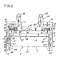
- Each holder 3 comprises a frame designated in its entirety by the reference numeral 29, this frame comprising an upper member or crosspiece 31, and a lower member or crosspiece 33 and vertical side members 35 and 37, member 35 being referred to as the left side member and member 37 being referred to as the right side member (left and right being as viewed from the open outside 25 of the holder).
- Each crosspiece has an elongated central body portion 39 extending from adjacent one side of the holder to adjacent the other side, integral arms 41 extending rearwardly from the ends of the body portion 39, and extensions 42 and 43 extending outwardly and forwardly from the left and right ends of the body 39.
- Each of the arms 41 has a pin 45 extending downwardly adjacent its rearward end, these pins corresponding generally to pins 98 shown in said U.S. patent 4,642,975, removably receivable in holes 47 in blocks 49 carried by the chains 11 and 13, these blocks corresponding generally to the blocks 100 shown in said patent.
- the side frame members 35 and 37 shown as constituted by bars of square cross section, are secured at their upper ends and adjacent but above their lower ends in forwardly facing notches 51 in the end extensions 42 and 43 of the upper and lower crosspieces 31 and 33, these side frame members being in a vertical plane forward of the vertical plane of the front edges of the body portions 39 of the crosspieces.
- a bar 53 shown as of square cross section like the side frame members 35 and 37, extends horizontally between the side frame members 35 and 37 at their lower ends below the level of the lower crosspiece 33.
- the vertical side frame bars 35 and 37 and the horizontal bar 53 extending between bars 35 and 37 at their lower ends form a back 55 for the holder engageable by the rear wall of a carton C inserted in the holder, as will appear.
- the holder has left and right side members 57 and 59 extending forward from the back 55 at the sides thereof.
- the right side 59 is fixed relative to the back 55 while the left side 57 is movable relative to the back toward and away from the fixed right side 59 and engageable with the left side of an erected carton in the holder to hold it against the fixed right side 59, i.e., to hold the carton with its right side engaging the right side of the holder.
- the fixed right side 59 of the carton holder is constituted by a plate secured to the outside of the vertical right side member or back bar 35 and extending forward therefrom at right angles to the plane of the forward face of the back 55, this plate being a relatively long and narrow rectangular plate having a width so related to the width of each side wall of the carton as to extend forward from the front face of the right back bar 35 (and the front face of the lower back bar 53) a distance corresponding generally to the width of the carton side wall, and a length such as to extend the full height of the holder.
- the plate 59 is secured at its upper end and adjacent its lower end on the inside of forward-reaching portions 61 of the right end extensions 43 of the upper and lower crosspieces 31 and 33, fitting in the right-hand notches 51 in the crosspieces between the bars 35 and said forward-reaching portions 61 of said extensions.
- a carton C is retained in the holder by the carton-retaining means 27, which comprises a first latch member 63 associated with the fixed (right) side of the holder and a second latch member 65 associated with the other side.
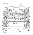
- the first latch member 63 is movable relative to the fixed side of the holder between a retracted open position such as shown in solid lines in Fig. 3 wherein it enables entry of a carton in the holder and discharge of a carton from the holder and the closed position in which it is shown in Fig. 2 and in phantom in Fig. 3 wherein it retains the carton in the holder.
- the latch member 63 is fastened on the end of an arm 67 of lever means designated in its entirety by the reference numeral 69, this lever means including a vertical shaft 71 pivoted for swinging movement at its upper and lower ends as indicated at 73 and 75 in the extensions 43 of the upper and lower crosspieces 31 and 33.
- the arm 67 extends forward from the shaft 71 just above the level of the lower crosspiece 33 and the latch member 63 extends laterally from arm 67 at the front of the right side plate 59 of the holder.
- the latch member 63 is beveled at its inner end forming a cam surface 77 engageable by a carton entering the holder to swing the latch member outwardly.
- the shaft 71 has an arm 79 extending rearwardly at its upper end.
- An arm 81 extends inwardly from the rear end of arm 79 and has a roller 83 at its inner end.
- a coil compression spring 85 acts from a block 87 on the bottom of the upper crosspiece 31 against the arm 79 to bias the shaft 71 to swing in the direction (clockwise as viewed from above) for swinging the latch member 63 to the closed carton-holding position in which it is shown in Fig. 2 and in phantom in Fig. 3 for holding a carton in the holder, this position being determined by engagement of a shim 89 on the inside of the arm 67 with the outside of the fixed side plate 59.
- the shaft is swingable in the opposite direction by actuation of arm 81 as will appear to swing the latch member 63 to its open position against the closing bias of spring 85.
- the movable left side 57 of the holder comprises a relatively long and narrow rectangular plate pivoted as indicated at 91 on upper and lower arms 93 and 95 of lever means designated in its entirety by the reference numeral 97, this lever means including a vertical shaft 99 (similar to 71) pivoted for swinging movement at its upper and lower ends as indicated at 101 and 103 in the extensions 42 at the left of the upper and lower crosspieces 31 and 33.
- the lower arm 95 is at the same level as arm 67.
- Latch member 65 extends laterally from arm 95 at the front of the left side plate 57 of the holder, in fixed relation thereto.
- the shaft 99 has an arm 107 extending rearwardly at its upper end.
- An arm 109 extends inwardly from the rear end of arm 107 and has a roller 111 at its inner end.
- a coil compression spring 113 acts from a block 115 on the bottom of the upper crosspiece against the arm 107 to bias the shaft 99 to swing in the direction (counterclockwise as viewed from above) for swinging the movable side plate 57 of the holder to the inner carton-holding position in which it is shown in Fig. 2 and in phantom in Fig.
- the pivoting at 91 of the side plate 57 to each of the arms 93 and 95 comprises a stud 119 on the outside of the plate in a horizontal slot 121 in the respective arm and a pivot pin 123, the arrangement being such that the plate 57 is pivotally mounted on arms 93 and 95 of the lever means 97 for swinging on a vertical axis generally in a vertical plane at right angles to plate 57 extending centrally of the width of the plate for flatwise engagement with the side of the carton.
- Fig. 1 there is generally indicated at 125 at each of stations 5, 9 and 15 means for effecting opening of the carton-retaining means 27 of each carton holder 3, for entry of a carton in the holder at station 5 and discharge of a carton at station 9 or 15 and closing of the carton-retaining means to retain a carton in the holder as it progresses from station 5 to station 7 and thence to stations 15 and 9.
- Fig. 1 there is generally indicated at 125 at each of stations 5, 9 and 15 means for effecting opening of the carton-retaining means 27 of each carton holder 3, for entry of a carton in the holder at station 5 and discharge of a carton at station 9 or 15 and closing of the carton-retaining means to retain a carton in the holder as it progresses from station 5 to station 7 and thence to stations 15 and 9.
- means 125 at each of stations 5, 9 and 15 is shown to comprise a cam track or rail 127 movable from a retracted position clear of the rollers 83 and 111 of the two lever means 69 and 81 of a holder into a position for engagement by these rollers as the holder reaches a respective station 5, 9, 15 for operating the lever means 69 to swing open the latch member 63 and for operating the lever means 97 to swing open the movable side plate 57 and the associated latch member 65.
- the rollers ride up an up ramp of the track on to a central dwell section of the track for swinging the two lever means from their retracted to their open position, and as the holder leaves the station the rollers ride off the central section and down a down ramp of the track for releasing the lever means for their closing swing as the holder moves away from the station.
- Means for moving the track 127 away from and back to its retracted position is shown in Figures 3 and 5 to comprise a pair of air cylinders each designated 129, these cylinders being suitably controlled by means indicated generally at 131 for operation on each dwell of the conveyor to move the track to the operative position for effecting the opening swing of the two lever means 69 and 81 of each of the holders at stations 5, 9 and 15, and then ultimately returning the track to a retracted position.
- FIG. 7 An alternative of the means 125 at each of stations 5 and 9 for the opening of the carton-retaining means 27 of each carton holder 3 for entry of a carton in the holder at station 5 and discharge of a carton at station 9 and for the closing thereof is shown in Figure 7 to comprise a cam track or cam rail 133 suitably mounted in fixed position at the respective station 5, 9, having the central section and ramps as shown so that as a holder 3 reaches the station, the rollers 111 and 83 ride up on the up ramp to the central section and the two lever means 97 and 69 thereby swing from their retracted to their open position, and as the holder moves away from the station, the rollers ride down the down ramp and release the lever means for their closing swing.
- a cam track or cam rail 133 suitably mounted in fixed position at the respective station 5, 9, having the central section and ramps as shown so that as a holder 3 reaches the station, the rollers 111 and 83 ride up on the up ramp to the central section and the two lever means 97 and 69
- vacuum gripper means corresponding to that indicated at 103 in EP-A-0295932 for drawing an opened carton into the opened holder 3 at station 5 and at 137 and 139 are indicated pusher means corresponding to that indicated at 214 and 238 in said U.S. patent 4642975 for ejecting (discharging ⁇ a carton C from an opened holder at stations 15 and 9.
- the vacuum gripper means and pusher means are operable through the opening indicated at 141 in the back 55 of the holder 3 bounded at the sides by bars 35 and 37 and at the bottom by bar 53.
- the back is offset forward of the central portions 39 both of the upper and lower crosspieces 31 and 33, and leaves the top of the back open for bulging out of the back wall of the carton as disclosed in the aforesaid U.S. application.
- the left side plate 57 swings in against the left side wall of the carton, pivotally adjusting itself thereto, and acts to hold the carton with its right side against the right side plate 59, thereby ensuring that the carton as ultimately sealed at top and bottom will be squared up with its top and bottom flaps in alignment, despite variations in dimensions and squareness such as may be encountered in cartons in a given run of cartons.
- This is to be distinguished from the arrangement shown in the aforesaid United Kingdom patent application No. 2,061,219 where both side walls of each carton holder are pivoted (at 52) and both are biased in the closing direction by springs (not shown).
- the holders or buckets 3 are readily changeable for accommodating cartons of different widths, depths and lengths and, with the cartons held in the holders or buckets by the latch members 63 and 65, no adjustable external rail is needed.
Landscapes
- Engineering & Computer Science (AREA)
- Microelectronics & Electronic Packaging (AREA)
- Mechanical Engineering (AREA)
- Supplying Of Containers To The Packaging Station (AREA)
- Container Filling Or Packaging Operations (AREA)
- Auxiliary Devices For And Details Of Packaging Control (AREA)
- Specific Conveyance Elements (AREA)
Applications Claiming Priority (2)
| Application Number | Priority Date | Filing Date | Title |
|---|---|---|---|
| US07/244,717 US4891928A (en) | 1988-09-14 | 1988-09-14 | Carton loading machine |
| US244717 | 1988-09-14 |
Publications (1)
| Publication Number | Publication Date |
|---|---|
| EP0359538A1 true EP0359538A1 (fr) | 1990-03-21 |
Family
ID=22923846
Family Applications (1)
| Application Number | Title | Priority Date | Filing Date |
|---|---|---|---|
| EP89309276A Withdrawn EP0359538A1 (fr) | 1988-09-14 | 1989-09-13 | Machine de chargement de cartons |
Country Status (4)
| Country | Link |
|---|---|
| US (1) | US4891928A (fr) |
| EP (1) | EP0359538A1 (fr) |
| JP (1) | JPH02191105A (fr) |
| CA (1) | CA1294929C (fr) |
Cited By (2)
| Publication number | Priority date | Publication date | Assignee | Title |
|---|---|---|---|---|
| WO1999048760A1 (fr) * | 1998-03-26 | 1999-09-30 | Stamford Packaging Systems Limited | Etuyeuse |
| EP1916191A1 (fr) * | 2006-10-25 | 2008-04-30 | MARCHESINI GROUP S.p.A. | Dispositif pour la préhension et le transfert d'articles, en particulier des boîtes |
Families Citing this family (13)
| Publication number | Priority date | Publication date | Assignee | Title |
|---|---|---|---|---|
| US5194065A (en) * | 1991-12-13 | 1993-03-16 | Elopak Systems A.G. | Carton squaring mechanism |
| IT1258521B (it) * | 1992-04-14 | 1996-02-27 | Amrp Handels Ag | Dispositivo di presa degli astucci in macchine astucciatrici automatiche |
| US5481854A (en) * | 1993-09-24 | 1996-01-09 | Carter Control Systems, Inc. | Method of and apparatus for inserting trays of articles into sleeves |
| US5517798A (en) * | 1994-11-07 | 1996-05-21 | The Paxall Group, Inc. | Carton conveyor and loading apparatus |
| US6729103B1 (en) * | 1994-11-10 | 2004-05-04 | Hartness International, Inc. | Continuous circular motion case packing and depacking apparatus and method |
| US20030106288A1 (en) * | 1994-11-10 | 2003-06-12 | Hartness Thomas Patterson | Continuous circular motion case packing and closure apparatus and method |
| WO2001028856A1 (fr) * | 1999-10-15 | 2001-04-26 | Hartness International, Inc. | Appareil et procede d'encaissage et de decaissage a mouvement circulaire continu |
| US6725629B2 (en) | 2001-04-26 | 2004-04-27 | Triangle Package Machinery Company | Horizontal cartoner system and method for the use thereof |
| US7735296B2 (en) * | 2007-09-17 | 2010-06-15 | Z Automation Company, Inc. | Apparatus and method for a carton carrier |
| US9309017B2 (en) * | 2010-02-24 | 2016-04-12 | H. J. Paul Langen | Item loading apparatus |
| ES2524414T3 (es) * | 2012-09-10 | 2014-12-09 | Multivac Sepp Haggenmüller Gmbh & Co Kg | Máquina de cierre de cubetas |
| US10358244B2 (en) | 2015-10-26 | 2019-07-23 | Triangle Package Machinery Co. | Rotatable sealing jaw assembly for a form, fill and seal machine |
| FR3063718B1 (fr) * | 2017-03-07 | 2019-04-19 | Adial | Chariot pour distributeur automatique de produits alimentaires prepares, notamment de pizza |
Citations (3)
| Publication number | Priority date | Publication date | Assignee | Title |
|---|---|---|---|---|
| US2358292A (en) * | 1941-09-15 | 1944-09-12 | Redington Co F B | Conveyer |
| US2679966A (en) * | 1950-10-14 | 1954-06-01 | Diced Cream Of America Co | Ice cream packaging machine |
| GB2061219A (en) * | 1979-10-22 | 1981-05-13 | Baker Perkins Holdings Ltd | Apparatus for forming, filling, sealing and cartoning bags |
Family Cites Families (5)
| Publication number | Priority date | Publication date | Assignee | Title |
|---|---|---|---|---|
| US1275759A (en) * | 1915-04-12 | 1918-08-13 | Clarence H Russell | Carton-forming machine. |
| US1873059A (en) * | 1928-09-27 | 1932-08-23 | Package Machinery Co | Carton opening and filling machine |
| US3378128A (en) * | 1966-07-08 | 1968-04-16 | Fmc Corp | Carton transfer apparatus |
| US3517477A (en) * | 1967-10-06 | 1970-06-30 | Molins Machine Co Ltd | Article handling apparatus |
| US4642975A (en) * | 1986-02-03 | 1987-02-17 | H. J. Langen & Sons Limited | Carton loading machine |
-
1988
- 1988-09-14 US US07/244,717 patent/US4891928A/en not_active Expired - Fee Related
-
1989
- 1989-09-11 CA CA000610894A patent/CA1294929C/fr not_active Expired - Fee Related
- 1989-09-13 EP EP89309276A patent/EP0359538A1/fr not_active Withdrawn
- 1989-09-14 JP JP1239799A patent/JPH02191105A/ja active Pending
Patent Citations (3)
| Publication number | Priority date | Publication date | Assignee | Title |
|---|---|---|---|---|
| US2358292A (en) * | 1941-09-15 | 1944-09-12 | Redington Co F B | Conveyer |
| US2679966A (en) * | 1950-10-14 | 1954-06-01 | Diced Cream Of America Co | Ice cream packaging machine |
| GB2061219A (en) * | 1979-10-22 | 1981-05-13 | Baker Perkins Holdings Ltd | Apparatus for forming, filling, sealing and cartoning bags |
Cited By (4)
| Publication number | Priority date | Publication date | Assignee | Title |
|---|---|---|---|---|
| WO1999048760A1 (fr) * | 1998-03-26 | 1999-09-30 | Stamford Packaging Systems Limited | Etuyeuse |
| EP1916191A1 (fr) * | 2006-10-25 | 2008-04-30 | MARCHESINI GROUP S.p.A. | Dispositif pour la préhension et le transfert d'articles, en particulier des boîtes |
| US7568325B2 (en) | 2006-10-25 | 2009-08-04 | Marchesini Group S.P.A. | Device for gripping and transferring articles, in particular boxes |
| EP2077235A3 (fr) * | 2006-10-25 | 2009-09-09 | MARCHESINI GROUP S.p.A. | Dispositif pour la préhension et le transfert d'articles, en particulier des boîtes |
Also Published As
| Publication number | Publication date |
|---|---|
| JPH02191105A (ja) | 1990-07-27 |
| CA1294929C (fr) | 1992-01-28 |
| US4891928A (en) | 1990-01-09 |
Similar Documents
| Publication | Publication Date | Title |
|---|---|---|
| US4891928A (en) | Carton loading machine | |
| EP1775223B1 (fr) | Station pour retirer et ériger les boîtes tubulaires pliées plats | |
| US4348853A (en) | Case opening and sealing apparatus | |
| US3775937A (en) | Automatic random size box sealer | |
| CA2415474C (fr) | Machine a former les cartons | |
| US4066009A (en) | Method for opening and erecting cartons | |
| EP0464002B1 (fr) | Dispositif pour former et insérer une pile d'emballages de type blister dans un carton | |
| EP1359092A1 (fr) | Procédé et dispositif pour faire basculer des piles d' objets dans une machine d' encartonnage | |
| US12006083B2 (en) | Pouch containment and carton loading | |
| EP0082348B1 (fr) | Appareil pour introduire des groupes de cigarettes dans des paquets de cigarettes | |
| US7998049B1 (en) | Cartoner for cartons having concave sides | |
| EP1373072B1 (fr) | Procede et dispositif permettant de fermer une boite par pliage d'un rabat de fermeture lateral | |
| US3613526A (en) | Carton feeding and erecting apparatus | |
| US4759167A (en) | Packaging machine | |
| US4224781A (en) | Apparatus for handling of unsealed slit boxes | |
| US3350841A (en) | Carton folding and filling machine | |
| EP2130773B1 (fr) | Dispositif et procédé de fabrication d'emballages de cigarettes | |
| US3143937A (en) | Machine for erecting cartons | |
| EP0295932A2 (fr) | Formage, remplissage et scellement des sacs et leur dépôt dans des boîtes | |
| US3753333A (en) | Carton handling machine | |
| GB2065585A (en) | Packaging apparatus | |
| US2849846A (en) | Carton closing machine | |
| US3462914A (en) | Box closing machine | |
| WO1997010948A1 (fr) | Appareil a haute vitesse de dressage d'une forme et procedes associes | |
| US1936338A (en) | Universal continuous folder for boxes |
Legal Events
| Date | Code | Title | Description |
|---|---|---|---|
| PUAI | Public reference made under article 153(3) epc to a published international application that has entered the european phase |
Free format text: ORIGINAL CODE: 0009012 |
|
| AK | Designated contracting states |
Kind code of ref document: A1 Designated state(s): AT BE CH DE FR GB IT LI LU NL SE |
|
| 17P | Request for examination filed |
Effective date: 19900602 |
|
| STAA | Information on the status of an ep patent application or granted ep patent |
Free format text: STATUS: THE APPLICATION HAS BEEN WITHDRAWN |
|
| 18W | Application withdrawn |
Withdrawal date: 19911216 |