EP0359848A1 - Installation de prévention de surchauffe de résistances de chauffage alimentées en courant continu - Google Patents
Installation de prévention de surchauffe de résistances de chauffage alimentées en courant continu Download PDFInfo
- Publication number
- EP0359848A1 EP0359848A1 EP88115411A EP88115411A EP0359848A1 EP 0359848 A1 EP0359848 A1 EP 0359848A1 EP 88115411 A EP88115411 A EP 88115411A EP 88115411 A EP88115411 A EP 88115411A EP 0359848 A1 EP0359848 A1 EP 0359848A1
- Authority
- EP
- European Patent Office
- Prior art keywords
- resistor
- heating resistor
- comparator circuit
- switching device
- temperature
- Prior art date
- Legal status (The legal status is an assumption and is not a legal conclusion. Google has not performed a legal analysis and makes no representation as to the accuracy of the status listed.)
- Withdrawn
Links
- 238000010438 heat treatment Methods 0.000 title claims abstract description 67
- 238000013021 overheating Methods 0.000 title abstract description 3
- 239000003990 capacitor Substances 0.000 claims description 14
- 230000001419 dependent effect Effects 0.000 claims description 4
- 239000004065 semiconductor Substances 0.000 claims description 2
- 230000000694 effects Effects 0.000 abstract description 3
- 238000009529 body temperature measurement Methods 0.000 abstract 1
- 238000010586 diagram Methods 0.000 description 9
- 239000007788 liquid Substances 0.000 description 3
- 238000011161 development Methods 0.000 description 2
- 230000018109 developmental process Effects 0.000 description 2
- 238000005259 measurement Methods 0.000 description 2
- 230000004913 activation Effects 0.000 description 1
- 238000002485 combustion reaction Methods 0.000 description 1
- 238000001816 cooling Methods 0.000 description 1
- 230000006378 damage Effects 0.000 description 1
- 230000007423 decrease Effects 0.000 description 1
- 238000001514 detection method Methods 0.000 description 1
- 238000001704 evaporation Methods 0.000 description 1
- 230000008020 evaporation Effects 0.000 description 1
- 238000007654 immersion Methods 0.000 description 1
- 238000000034 method Methods 0.000 description 1
- 238000012544 monitoring process Methods 0.000 description 1
- 230000000284 resting effect Effects 0.000 description 1
- 238000004804 winding Methods 0.000 description 1
Images
Classifications
-
- F—MECHANICAL ENGINEERING; LIGHTING; HEATING; WEAPONS; BLASTING
- F02—COMBUSTION ENGINES; HOT-GAS OR COMBUSTION-PRODUCT ENGINE PLANTS
- F02P—IGNITION, OTHER THAN COMPRESSION IGNITION, FOR INTERNAL-COMBUSTION ENGINES; TESTING OF IGNITION TIMING IN COMPRESSION-IGNITION ENGINES
- F02P19/00—Incandescent ignition, e.g. during starting of internal combustion engines; Combination of incandescent and spark ignition
- F02P19/02—Incandescent ignition, e.g. during starting of internal combustion engines; Combination of incandescent and spark ignition electric, e.g. layout of circuits of apparatus having glowing plugs
- F02P19/025—Incandescent ignition, e.g. during starting of internal combustion engines; Combination of incandescent and spark ignition electric, e.g. layout of circuits of apparatus having glowing plugs with means for determining glow plug temperature or glow plug resistance
-
- F—MECHANICAL ENGINEERING; LIGHTING; HEATING; WEAPONS; BLASTING
- F02—COMBUSTION ENGINES; HOT-GAS OR COMBUSTION-PRODUCT ENGINE PLANTS
- F02P—IGNITION, OTHER THAN COMPRESSION IGNITION, FOR INTERNAL-COMBUSTION ENGINES; TESTING OF IGNITION TIMING IN COMPRESSION-IGNITION ENGINES
- F02P19/00—Incandescent ignition, e.g. during starting of internal combustion engines; Combination of incandescent and spark ignition
- F02P19/02—Incandescent ignition, e.g. during starting of internal combustion engines; Combination of incandescent and spark ignition electric, e.g. layout of circuits of apparatus having glowing plugs
- F02P19/021—Incandescent ignition, e.g. during starting of internal combustion engines; Combination of incandescent and spark ignition electric, e.g. layout of circuits of apparatus having glowing plugs characterised by power delivery controls
- F02P19/022—Incandescent ignition, e.g. during starting of internal combustion engines; Combination of incandescent and spark ignition electric, e.g. layout of circuits of apparatus having glowing plugs characterised by power delivery controls using intermittent current supply
Definitions
- the invention relates to a circuit arrangement for protection against overtemperature in DC-powered resistance heaters according to the preamble of claim 1.
- Difficulties can arise when measuring the current using a shunt resistor of the type of the known circuit arrangement and the temperature of the glow plug to be determined therefrom, especially when the glow plugs of the diesel engine are operated in parallel.
- the internal resistance of such glow plugs is in the order of a few 100 mOhm.
- a parallel connection of these glow plugs leads to one even lower overall resistance.
- the invention has for its object to develop a circuit arrangement of the type mentioned so that a reliable temperature detection of the heating resistor is possible with simple means.
- the invention is based on the principle that heating resistors have a temperature dependence of their electrical resistance. This temperature dependence of the electrical resistance can be used as a measure of the instantaneous temperature of the heating resistor and can thus be used in a simple manner for monitoring a predetermined limit temperature.
- the heating resistor is fed by a DC voltage source.
- the heating resistor temperature is monitored as follows: If the limit temperature is reached or exceeded, the current flow through the heating resistor is switched off for a certain period of time t a . After this period, the current flow is switched on for a minimum time t e min . If the limit temperature is still exceeded afterwards, an immediate shutdown takes place for the period t a . If, on the other hand, the temperature falls below the limit, the heating resistor is now continuously flowed through until the limit temperature is reached again.
- the characteristic temperature dependence of the heating resistor is measurable and z. B. can be graphically represented in a resistance-temperature diagram. If such a resistance-temperature diagram is determined for a heating resistor, the associated temperature can be inferred for each resistance value that occurs.
- the characteristic temperature dependence of a heating resistor can therefore be assumed to be known and used as a parameter for the temperature control of the heating resistor.
- the circuit arrangement according to the invention can be used wherever the temperature of a temperature-dependent heating resistor must be monitored. Is z. B. a resting or flowing liquid heated by an electrical heating resistor or heated quickly (z. B. immersion heater, etc.), a high electrical heating power is required, but can lead to destruction of the heating resistor in the absence of liquid. The lack of liquid can e.g. B. be caused by evaporation of the same or by stopping the flow. In such cases, self-protection of the heating resistor is possible in a simple manner with the circuit arrangement according to the invention.
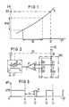
- FIG. 1 shows a resistance-temperature characteristic curve K of a heating resistor.
- a positive resistance-temperature characteristic can be seen from this characteristic curve, i.e. that the resistance R of the heating element increases with increasing temperature T.
- a temperature working range TA with the associated resistance value range WW is defined.
- the diagram also has a limit temperature TG with an associated resistance value WG. If the limit temperature TG of the heating resistor is exceeded, there is a risk of the heating resistor being destroyed. To avoid this danger, a heating resistor should always be operated in the temperature working range TA. Heating resistors with negative resistance-temperature characteristics are also known. If a resistance-temperature characteristic curve K is recorded for a heating resistor, then the associated temperature T can be assumed to be known when the resistance value of the heating resistor is known.
- a temperature-dependent heating resistor RH with its first connection 1 at reference potential is connected with its second connection 2 via the series connection of a first resistor R1 with a switching device SR to the positive pole of a DC voltage source U B.
- the series connection of a second resistor R2 and a third resistor R3 is connected in the manner of a resistor bridge circuit WB.
- the output terminals of the resistance bridge circuit WB that is, the connection points P1 between the first resistor R1 and the heating resistor RH and P2 between the second resistor R2 and third resistor R3 are connected to the input terminals of a first comparator circuit V1.
- connection point P1 is connected to the first input terminal 3, which, for. B. the inverting input of the comparator circuit V1 can be connected, while the connection point P2 is connected to the second input terminal 4, which in this case is the non-inverting input of the comparator circuit V1.
- the voltage drop across the heating resistor RH thus reaches the first input terminal 3 of the first comparator circuit V1, while the voltage drop across the third resistor R3 is applied as a reference voltage to the second input terminal 4 of the first comparator circuit V1.
- the output terminal 5 of the first comparator circuit V1 is connected to a control device ST.
- This control device ST provides for the switching device SR to be closed continuously or opened in a pulsed manner via a control line STL. Whether the switching device SR is opened in pulses or remains closed continuously depends on the output signal of the first comparator circuit V1.
- the resistance ratio of the second resistor R2 to the third resistor R3 is dimensioned such that it corresponds to the resistance ratio of the first resistor R1 to the heating resistor RH at the limit temperature TG. If the voltage drop across the heating resistor RH is lower than the reference voltage drop across the third resistor R3, the switching device SR remains closed, controlled by the output signal of the first comparator circuit V1 with a downstream control device ST. The lower voltage drop across the heating resistor RH indicates that the limit temperature TG has not yet been reached. Due to the closed switching device SR, the temperature at the heating resistor RH can increase further.
- the voltage drop across the heating resistor RH becomes greater than the voltage drop across the resistor R3.
- the output of the first comparator circuit V1 thus also changes its state and the switching device SR is switched over the Control device ST only closed in pulses.
- the time period for the closing of the switching device SR is t e , while the switching device remains open for the time period t a .
- the temperature of the heating resistor RH cannot increase any further.
- the temperature of the heating resistor RH drops again below the limit temperature TG.
- the control device ST is accordingly shown that the switching device SR must be closed again until the limit temperature TG is reached.
- the switching device SR is activated by the control device ST via a control line STL.
- the control device ST is supplied with a direct voltage U S via connecting lines.
- the pulse diagram shown in FIG. 3 for controlling the heating resistor RH according to FIG. 2 illustrates the mode of operation of the circuit arrangement according to the invention.
- the voltage UP1 applied at the connection point P1 is shown as a function of the time t.
- the switching device SR With the switching device SR closed, the voltage UP11 is applied to P1, with the switching device SR open, on the other hand, 0.
- the switching device SR is closed until the time t 1, so that the heating resistor RH can heat up according to the invention.
- the limit temperature TG is at least reached.
- the switching device SR is opened by the control device ST until time t 2.
- a brief switch-on of the switching device SR for the period t e ensures that the comparator circuit V1 can be used to determine whether the limit temperature TG is still exceeded or has already fallen below.
- the limit temperature TG is still exceeded at time t 2.
- the control device ST opens the switching device SR again for the Time period t a .
- the limit temperature TG is undershot.
- the first comparator circuit V1 and the control device ST now ensure that the switching device SR is closed until current can flow through the heating resistor RH until it reaches the limit temperature TG again.
- the limit temperature TG is reached and the process can be repeated again.
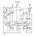
- FIG 4 shows a circuit arrangement according to the invention for protecting a heating resistor RH against overtemperature in detail.
- the same reference numerals in this FIG 4 denote the already known circuit parts.
- the cathode connection of a diode D is connected to the second input terminal 4 of the first comparator circuit V1, the anode connection of which is connected to a voltage divider consisting of a fourth resistor R4 and a fifth resistor R5 and connected to the direct voltage source U B.
- a first capacitor C1 is also connected between the reference potential and the first input terminal 3 of the first comparator circuit V1.
- a sixth resistor R6 is arranged between the first input terminal 3 of the first comparator circuit V1 and the first connection point P1.
- a seventh resistor R7 is connected between the second input terminal 4 and the connection point P2.
- the control device ST has a second comparator circuit V2 with an inverting input 6, a non-inverting input 7 and an output terminal 8.
- the inverting input 6 is connected to the connection point of two resistors R10, R9 connected in series, which are connected between a DC voltage source U S and reference potential are connected in series.
- Another voltage divider, consisting of the resistor R8 and a capacitor C2 is also connected between this voltage source U S and the reference potential.
- connection point of this voltage divider is at the non-inverting input 7 of the second comparator circuit V2 and at the output terminal 5 of the first comparator circuit V1 switched.
- the capacitor C2 lies between the output terminal 5 and the reference potential.
- the output terminal 8 of the second comparator circuit V2 is connected to the base terminal B of an npn transistor T and via a resistor R12 to the positive pole of the voltage source U S.
- the emitter terminal E of the npn transistor T is connected to the reference potential, while the collector terminal C is connected to a terminal of a further resistor R11 and via the coil winding of a relay to the positive pole of the voltage source U S.
- the other connection of the resistor R11 is connected to the inverting input terminal 6 of the second comparator circuit V2.
- the resistor R6 and capacitor C1 determine the switch-on time t e and the resistor R8 determines the switch-off time t a with the capacitor C2 connected in series. It is therefore expedient to choose the capacitance of the capacitor C1 in the nF range and the capacitance of the capacitor C2 in the ⁇ F range.
- the first comparator circuit V1 and the second comparator circuit V2 are operational amplifiers with open collector outputs.
- the voltage U S can also be identical to the voltage U B.
- the supply voltage U OP of the operational amplifier that is to say the first comparator circuit V1 and the second comparator circuit V2, must be greater than the voltage U B and U S.
- the resistor R1 connected in series with the heating resistor RH has a low resistance compared to the heating resistor RH.
- the mode of operation of the circuit arrangement shown in FIG. 4 results as follows: As long as the switching device SR, ie here z. B. the relay is closed and the limit temperature TG has not yet been reached, the voltage at the inverting input 3 of the first comparator circuit V1 is lower than that at the non-inverting input 4.
- the low-resistance dimensioning of the resistor R1 ensures that at the input terminal 3 almost the voltage U B is present and the diode D, the anode connection of a voltage of about U B / 2 lies (the resistors R5 and R6 are approximately the same size) does not conduct.
- the output 5 of the first comparator circuit V1 is accordingly open in relation to the reference potential.
- the capacitor C2 can thus charge up to the voltage U S via the resistor R8.
- the voltages present at the input terminals 6 and 7 of the second comparator circuit V2 have the effect that the output 8 is also open.
- the transistor T thus conducts and the relay of the switching device SR is attracted. Current therefore continues to flow through the heating resistor RH, which further heats up as a result.
- the output terminal 5 of the first comparator circuit V1 is pulled to ground, as a result of which the second capacitor C2 can quickly discharge and thus the output 8 of the second comparator circuit V2 is also pulled to ground.
- the transistor T turns off and the relay turns off.
- the relay of the switching device SR is switched off, the voltage applied to the input terminal 3 is very small compared to the voltage applied to the input terminal 4.
- the input terminal 4 of the first comparator circuit V1 is held at half the voltage U B / 2 via the diode D, while the voltage at the input terminal 3 is almost at reference potential.
- the output terminal 5 of the first comparator circuit V1 is thus open again, as a result of which the capacitor C2 can charge up via the resistor R8.
- the output 8 becomes open again and the transistor T can switch on the relay again. This means that the initial state is reached again.
- the resistor R11 has a feedback effect, which results in a switching hysteresis in the second comparator circuit V2 and thus vibrations in the circuit arrangement are prevented.
- the heating resistor RH will be cooled again during the switch-off phase determined by the time constant R8 * C2, that is to say while the relay of the switching device SR is opening, so that the heating resistor RH flowed through again until the limit temperature TG was reached. If the temperature at the heating resistor RH has not yet dropped below the limit temperature TG, there is only a short switch-on attempt for the time period t e , the time constant of which is determined by the resistor R6 and the capacitor C1.
Landscapes
- Engineering & Computer Science (AREA)
- Chemical & Material Sciences (AREA)
- Combustion & Propulsion (AREA)
- Mechanical Engineering (AREA)
- General Engineering & Computer Science (AREA)
- Control Of Temperature (AREA)
- Control Of Resistance Heating (AREA)
Priority Applications (2)
| Application Number | Priority Date | Filing Date | Title |
|---|---|---|---|
| EP88115411A EP0359848A1 (fr) | 1988-09-20 | 1988-09-20 | Installation de prévention de surchauffe de résistances de chauffage alimentées en courant continu |
| JP24324989A JPH02109288A (ja) | 1988-09-20 | 1989-09-18 | 直流電流による抵抗加熱における超過温度保護用回路装置 |
Applications Claiming Priority (1)
| Application Number | Priority Date | Filing Date | Title |
|---|---|---|---|
| EP88115411A EP0359848A1 (fr) | 1988-09-20 | 1988-09-20 | Installation de prévention de surchauffe de résistances de chauffage alimentées en courant continu |
Publications (1)
| Publication Number | Publication Date |
|---|---|
| EP0359848A1 true EP0359848A1 (fr) | 1990-03-28 |
Family
ID=8199340
Family Applications (1)
| Application Number | Title | Priority Date | Filing Date |
|---|---|---|---|
| EP88115411A Withdrawn EP0359848A1 (fr) | 1988-09-20 | 1988-09-20 | Installation de prévention de surchauffe de résistances de chauffage alimentées en courant continu |
Country Status (2)
| Country | Link |
|---|---|
| EP (1) | EP0359848A1 (fr) |
| JP (1) | JPH02109288A (fr) |
Cited By (3)
| Publication number | Priority date | Publication date | Assignee | Title |
|---|---|---|---|---|
| WO2007033825A1 (fr) * | 2005-09-21 | 2007-03-29 | Beru Aktiengesellschaft | Procede de commande d'un groupe de bougies de prechauffage d'un moteur diesel |
| EP2085607A1 (fr) * | 2008-02-04 | 2009-08-05 | Robert Bosch GmbH | Prevision de panne pour une bougie de préchauffage alimentée avec une séquence continue de impulsions de tension |
| DE102006025834B4 (de) * | 2006-06-02 | 2010-05-12 | Beru Ag | Verfahren zum Steuern einer Glühkerze in einem Dieselmotor |
Citations (6)
| Publication number | Priority date | Publication date | Assignee | Title |
|---|---|---|---|---|
| US4274034A (en) * | 1979-10-15 | 1981-06-16 | C&D Enterprises | Glow plug driver |
| GB2070803A (en) * | 1980-03-03 | 1981-09-09 | Diesel Kiki Co | Preheating control apparatus for diesel engines |
| US4307688A (en) * | 1980-02-07 | 1981-12-29 | General Motors Corporation | Diesel engine glow plug energization control system |
| WO1982002744A1 (fr) * | 1981-01-30 | 1982-08-19 | Andreasson Jan Yngve Nils | Systeme d'allumage |
| US4500775A (en) * | 1982-04-02 | 1985-02-19 | Nippondenso Co., Ltd. | Method and apparatus for detecting an open circuit in a glow plug group for combination with a glow plug heating control circuit |
| US4530321A (en) * | 1984-01-12 | 1985-07-23 | International Harvester Company | Glow plug control circuit |
-
1988
- 1988-09-20 EP EP88115411A patent/EP0359848A1/fr not_active Withdrawn
-
1989
- 1989-09-18 JP JP24324989A patent/JPH02109288A/ja active Pending
Patent Citations (7)
| Publication number | Priority date | Publication date | Assignee | Title |
|---|---|---|---|---|
| US4274034A (en) * | 1979-10-15 | 1981-06-16 | C&D Enterprises | Glow plug driver |
| US4307688A (en) * | 1980-02-07 | 1981-12-29 | General Motors Corporation | Diesel engine glow plug energization control system |
| GB2070803A (en) * | 1980-03-03 | 1981-09-09 | Diesel Kiki Co | Preheating control apparatus for diesel engines |
| WO1982002744A1 (fr) * | 1981-01-30 | 1982-08-19 | Andreasson Jan Yngve Nils | Systeme d'allumage |
| WO1982002745A1 (fr) * | 1981-01-30 | 1982-08-19 | Andreasson Jan Yngve Nils | Systeme d'allumage |
| US4500775A (en) * | 1982-04-02 | 1985-02-19 | Nippondenso Co., Ltd. | Method and apparatus for detecting an open circuit in a glow plug group for combination with a glow plug heating control circuit |
| US4530321A (en) * | 1984-01-12 | 1985-07-23 | International Harvester Company | Glow plug control circuit |
Cited By (4)
| Publication number | Priority date | Publication date | Assignee | Title |
|---|---|---|---|---|
| WO2007033825A1 (fr) * | 2005-09-21 | 2007-03-29 | Beru Aktiengesellschaft | Procede de commande d'un groupe de bougies de prechauffage d'un moteur diesel |
| US7957885B2 (en) | 2005-09-21 | 2011-06-07 | Kernwein Markus | Method for operating a group of glow plugs in a diesel engine |
| DE102006025834B4 (de) * | 2006-06-02 | 2010-05-12 | Beru Ag | Verfahren zum Steuern einer Glühkerze in einem Dieselmotor |
| EP2085607A1 (fr) * | 2008-02-04 | 2009-08-05 | Robert Bosch GmbH | Prevision de panne pour une bougie de préchauffage alimentée avec une séquence continue de impulsions de tension |
Also Published As
| Publication number | Publication date |
|---|---|
| JPH02109288A (ja) | 1990-04-20 |
Similar Documents
| Publication | Publication Date | Title |
|---|---|---|
| DE60119102T3 (de) | Elektronischer Schutzschalter | |
| EP0514839B1 (fr) | Circuit pour mesurer la capacité | |
| DE1763162C3 (de) | Ladeeinrichtung für eine gasdicht verschlossene Batterie | |
| DE2847097C2 (de) | Vorglühsystem zur Erleichterung des Kaltstarts eines Dieselmotors | |
| EP0315934B1 (fr) | Méthode pour le réglage de la température des bougies dans un moteur diesel et circuit pour la réalisation de la méthode | |
| EP0189086B1 (fr) | Elément à incandescence | |
| DE2827928C2 (de) | Anlaßschaltvorrriichtung für Diesel-Brennkraftmaschinen | |
| DE3007129C2 (fr) | ||
| DE2051488B2 (de) | Schaltungsanordnung zum schnelladen einer elektrischen batterie | |
| DE1264501B (de) | Bistabile Kippschaltung mit einem steuerbaren Gleichrichter | |
| DE2441501C3 (de) | Schaltungsanordnung zum stoßfreien Einschalten einer Last | |
| DE2926844C2 (de) | Vorglühsteuereinrichtung für Brennkraftmaschinen | |
| EP0004035B1 (fr) | Outil de soudage avec régulation de la température | |
| EP0356667B1 (fr) | Filtre pour carburants, spéciallement adapté pour moteurs diesel avec chauffage par résistance électrique | |
| EP0506668A1 (fr) | Procede et dispositif pour la surveillance du bon fonctionnement d'un dispositif de chauffage de sonde. | |
| EP0471332A1 (fr) | Assemblage de circuit pour le fonctionnement d'une lampe fluorescente | |
| EP0800334B1 (fr) | Circuit pour alimenter des lampes électriques | |
| DE3107994C2 (de) | Vorglühsteuereinrichtung für Dieselmotoren | |
| DE3738055A1 (de) | Verfahren zur temperaturregelung von gluehkerzen bei dieselmotoren und schaltungsanordnung zur durchfuehrung des verfahrens | |
| DE4331250C1 (de) | Vorrichtung zur Begrenzung des Einschaltstromes in einem Laststromkreis | |
| WO2003077397A1 (fr) | Dispositif chauffant a corps chauffant flexible | |
| DE4039990A1 (de) | Ueberlast- und kurzschlussschutzanordnung | |
| DE3522546C2 (fr) | ||
| EP0829939A2 (fr) | Circuit avec protection contre une surintensité d'un relais | |
| DE19740016C2 (de) | Schaltungsanordnung und Verfahren zum Betreiben einer Erregerspule einer elektromagnetisch betätigbaren, mechanischen Bremse eines Elektromotors |
Legal Events
| Date | Code | Title | Description |
|---|---|---|---|
| PUAI | Public reference made under article 153(3) epc to a published international application that has entered the european phase |
Free format text: ORIGINAL CODE: 0009012 |
|
| AK | Designated contracting states |
Kind code of ref document: A1 Designated state(s): AT BE CH DE ES FR GB GR IT LI LU NL SE |
|
| RBV | Designated contracting states (corrected) |
Designated state(s): AT DE FR GB IT NL |
|
| STAA | Information on the status of an ep patent application or granted ep patent |
Free format text: STATUS: THE APPLICATION IS DEEMED TO BE WITHDRAWN |
|
| 18D | Application deemed to be withdrawn |
Effective date: 19900929 |