EP0359851B1 - Installation d'allumage pour moteur à combustion interne - Google Patents
Installation d'allumage pour moteur à combustion interne Download PDFInfo
- Publication number
- EP0359851B1 EP0359851B1 EP88115472A EP88115472A EP0359851B1 EP 0359851 B1 EP0359851 B1 EP 0359851B1 EP 88115472 A EP88115472 A EP 88115472A EP 88115472 A EP88115472 A EP 88115472A EP 0359851 B1 EP0359851 B1 EP 0359851B1
- Authority
- EP
- European Patent Office
- Prior art keywords
- transister
- voltage
- emitter
- base
- reference voltage
- Prior art date
- Legal status (The legal status is an assumption and is not a legal conclusion. Google has not performed a legal analysis and makes no representation as to the accuracy of the status listed.)
- Expired - Lifetime
Links
Images


Classifications
-
- F—MECHANICAL ENGINEERING; LIGHTING; HEATING; WEAPONS; BLASTING
- F02—COMBUSTION ENGINES; HOT-GAS OR COMBUSTION-PRODUCT ENGINE PLANTS
- F02P—IGNITION, OTHER THAN COMPRESSION IGNITION, FOR INTERNAL-COMBUSTION ENGINES; TESTING OF IGNITION TIMING IN COMPRESSION-IGNITION ENGINES
- F02P3/00—Other installations
- F02P3/02—Other installations having inductive energy storage, e.g. arrangements of induction coils
- F02P3/04—Layout of circuits
- F02P3/05—Layout of circuits for control of the magnitude of the current in the ignition coil
- F02P3/051—Opening or closing the primary coil circuit with semiconductor devices
Definitions
- the present invention relates to an ignition device for an internal combustion engine having transistor switching means in series with an ignition coil for on-off controlling a primary current from a voltage source to said ignition coil to produce a high voltage for spark ignition, including a reference voltage generator for producing a reference voltage, a primary current detecting circuit for producing a voltage corresponding to a primary current of said ignition coil, a comparator for comparing said reference voltage (Vref) with said voltage produced by said primary current detecting circuit and a control circuit responsive to an output of said comparator to control a base voltage of said transistor switching means to a predetermined constant value.
- a reference voltage generator for producing a reference voltage
- a primary current detecting circuit for producing a voltage corresponding to a primary current of said ignition coil
- a comparator for comparing said reference voltage (Vref) with said voltage produced by said primary current detecting circuit
- a control circuit responsive to an output of said comparator to control a base voltage of said transistor switching means to a predetermined constant value.
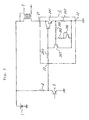
- Figure 3 shows an example of a conventional ignition device of this type, in which a reference numeral 1 depicts a power source, 2 an ignition coil, 3 an ignition device and 4 and 5 are a resistor and a transistor, respectively, constituting a circuit for producing a drive signal for the ignition device.
- a reference numeral 1 depicts a power source
- 2 an ignition coil
- 3 an ignition device
- 4 and 5 are a resistor and a transistor, respectively, constituting a circuit for producing a drive signal for the ignition device.
- the ignition device 3 includes an output terminal 31 connected to the ignition coil 2, a grounding terminal 32 and an input terminal 33 connected to the circuit.
- a signal is supplied to the input terminal 33 of the ignition device 3 such that, upon a turn-off of the transistor 5, a current flows from the power source 1 through the resistor 4 and an internal resistance 303 of the ignition device to a base of a Darlington power transistor 301 to turn the latter on to thereby supply a primary current to the ignition coil 2.
- a primary current detecting resistor 302 is provided between an emitter of the power transistor 301 and a grounding point so that a voltage across the resister 302 increases with increase of the primary current.
- a transister 307 has a base connected through a resister 304 to the emitter of the power transister 301, an emitter grounded and a collector connected to the base of the power transister 301. Between the base and the emitter of the transister 307, a circuit constituted with a resister 305 and a transister 306 is connected. When a voltage across the primary current detecting resister 302 exceeds a turn-on voltage of the transister 307, a current flows through the resister 304 to the base of the transister 307 and the resister 305. The collector of the transister 307 absorbs a portion of the base current of the power transister 301 correspondingly to a degree of conduction of the transister 307.
- the primary current of the ignition coil is limited to a constant value when a balance condition determined by the base current of the power transister 301, the voltage across the primary current detecting resister 302, the base current of the transister 307 and a current amplification factor of the transister circuit composed of the power transister 301 and the transister 307 is satisfied.
- the collector and the base of the transister 306 are short-circuited so that it functions as a diode. That is, a temperature dependency of the base-emitter voltage of the transister 307 is compensated for by a temperature dependency of base-emitter voltage of the transister 306 to thereby solving a temperature dependency problem of current limitation.
- the primary current of the ignition coil is limited to a constant value which is just enough for ignition, allowing a use of a relatively small power transister.
- the constant primary current means that a current amount to be absorbed by the transister 307 is constant, while the base current of the transister 301 varies with a variation of the source voltage. That is, it is impossible to obtain a constant current limitation value when the source voltage varies. For example, when the source voltage increases, the base current of the power transister 301 increases correspondingly. In order to absorb a current increment by means of the transister 307, it is necessary to increase the voltage across the primary current detecting resister, i. e., to increase the primary current, requiring a large power transister. On the contrary, when the source voltage decreases, the current limit value is lowered, causing an output of a secondary coil of the ignition coil to be lowered or a heat generation problem to occur.
- the transister 306 provided for compensation of temperature denpendency of the current limit value is not enough to cancel out a temperature dependent variation of a base-emitter voltage of the transistor 307 and that, due to the fact that the primary current detecting resistor 302 is of a metal having resistance varying with temperature, the current limit value is large at low temperature and small at high temperature.
- An object of the present invention is to provide an ignition device for an internal combustion engine which is capable of maintaining a current limit value constant for a variation of a source voltage and for a variation of temperature.
- the present invention provides an ignition device as set out in the opening paragraph of the present specification and is characterised by said reference voltage generator being a temperature compensated reference voltage generator comprising first and second transistors connected in parallel, the bases of said first and second transistors being connected together and the base of one of these transistors being connected together to the collector thereof; a first resistor connected between the emitter of the other transistor and ground potential; and second and third resistors connected in series between the base and emitter of said other transistor, the output of said reference voltage generator being connected to the junction point of said second and third resistors.
- said reference voltage generator being a temperature compensated reference voltage generator comprising first and second transistors connected in parallel, the bases of said first and second transistors being connected together and the base of one of these transistors being connected together to the collector thereof; a first resistor connected between the emitter of the other transistor and ground potential; and second and third resistors connected in series between the base and emitter of said other transistor, the output of said reference voltage generator being connected to the junction point of said second and third resistors.
- a power source and an ignition are depicted by reference numerals 1 and 2, respectively, and an ignition device according to the present invention is depicted by a reference numeral 3.
- a transister 5 is on-off controlled by an output signal of a control device which is not shown and has a collector connected to an input terminal 33 of the ignition device 3 and to a terminal of a resister 4 whose the other terminal is connected to the power source 1.
- the transister 5 supplies a drive signal for the ignition device 3.
- the latter has an output terminal 31, a grounding terminal 32 and an input terminal 33, as in the conventional device, and the output terminal 31 is connected to a primary terminal of the ignition coil 2.
- the input terminal 33 of the ignition device 3 is connected through an input protection resister 303 to a power transister 301 and a constant current control circuit 308 and the output terminal 31 is connected to a collector of the power transister 301.
- a primary current detecting resister 302 having a resistance r1 for detecting a current of the primary coil of the ignition coil is connected between an emitter of the power transister 301 and a grounding point 32, in parallel to a series connected resisters 304 and 305 having resistances r2 and r3, respectively.
- a junction of the resisters 304 and 305 is connected through a resister 352 to one of input terminals of a comparator composed of transisters 313 to 318 and a resister 353 of a constant current control circuit 308.
- the other input of the comparator is connected to an output of a reference voltage generator composed of transisters 319 to 322 and resisters 354, 355 and 356 having resistances r4, r5 and r6, respectively.
- a transister 325 and resisters 358 and 359 constitute an actuation circuit for the reference voltage generator and the comparator and transisters 323 and 324 and a resister 357 constitute a circuit for making the actuation circuit inoperative after the reference voltage generator and the comparator start to operate.
- the base voltage of the power transister becomes a sum of the above mentioned base-emitter voltage and the incremented voltage apeared on the resister 302, which is shown by a waveform b in Fig. 2. It is known that the base-emitter voltage of the power transister which is of Darlington type is in the order of 1.4 V.
- the transister 325 is firstly turned on and absorbs a current from bases of the transisters 318 to 320 and 323 which constitute a current mirror circuit through the resister 358 to thereby turn the transisters 318 to 320 and 328 of the current mirror circuit on.
- an emitter current thereof is substantially equal to its collector current.
- a sum of the resistances of the resisters 354 and 355 connected between the base-emitter of the transister 321 is set large such that a current flowing from the resister 355 to the resister 356 is small compared with the emitter current of the transister 321, a current flowing from the collector of the transister 320 to the resister 354 is small compared with the collector current of the transister 320. Therefore, the emitter current of the transister 321 becomes equal to the current flowing through the resister 356 and the emitter current of the transister 322 becomes equal to the collector current of the transister 320.
- the current I1 flowing through the resister 356 is determined by the resistance r6 of the resister 356 and a difference ⁇ V BE between the base-emitter voltage of the transister 322 and the base-emitter voltage of the transister 321.
- T absolute temperature
- ED321 emitter current density of transister 321
- the ratio of current density between the transisters 321 and 322 in the equation (2) is given by the following equation since an error component thereof can be made negligible by setting the values r4
- EA321 emitter area of transister 321
- EA320 emitter area of transister 320
- EA322 emitter area of transister 322
- EA319 emitter area of transister 319
- the reference voltage Vref provided by the reference voltage generator circuit is supplied from a junction of the resisters 354 and 355 connected between the base and the emitter of the transister 321 to a base of the transister 317.
- the reference voltage generator circuit operates when the base voltage Vb(301) of the power transister 301 satisfies the following condition: Vb ⁇ V BE (322) + V CE (320) (5) or Vb ⁇ ⁇ V BE + V CE (321) + V BE (319) (6) where V BE (322): base-emitter voltage of transister 322 V CE (320): collector-emitter saturation voltage V CE (321): collector-emitter saturation voltage V BE (319): base-emitter voltage of transister 319 Since base-emitter voltage and collector-emitter voltage of a transister are 0.7V and 0.1V, respectively, and ⁇ V BE ⁇ 0.25, generally, it can be operated by the base voltage of the Darlington connected power transister upon which the latter is turned on.
- the base of the transister 314 which constitutes an input of the comparator circuit is supplied with a voltage through the resister 352 which is a fraction of the voltage generated across the primary current detecting resister 302 and derived from the junction between the resisters 304 and 305.
- the base voltage V B (314) of the transister 314 is shown by a solid waveform c in Fig.
- V B (314) Ipr R1 R3/(R2 + R3) (7)
- Ipr primary current of ignition coil
- the comparator circuit operates when the base voltage Vb of the power transister 301 satisfies the following condition, Vb ⁇ Vref + V CE (315) + V BE (313) (8) where
- the operating voltage of the Darlington transisters 312 and 311 is V BE (311) + V BE (312) + V CE (313) (9) where
Landscapes
- Engineering & Computer Science (AREA)
- Chemical & Material Sciences (AREA)
- Combustion & Propulsion (AREA)
- Mechanical Engineering (AREA)
- General Engineering & Computer Science (AREA)
- Ignition Installations For Internal Combustion Engines (AREA)
Claims (3)
- Installation d'allumage pour un moteur à combustion interne comportant un moyen de commutation par transistor (301) en série avec une bobine d'allumage (2) pour une commande de marche-arrêt d'un courant primaire en provenance d'une source de tension (1) vers ladite bobine d'allumage (2) afin de produire une haute tension pour un allumage de bougie, comprenant un générateur de tension de référence (319 - 322, 354 - 356) pour produire une tension de référence (Vref), un circuit de détection de courant primaire (302, 304, 305, 352) pour produire une tension (VB) correspondant à un courant primaire de ladite bobine d'allumage (2), un comparateur (313 - 318) destiné à comparer ladite tension de référence (Vref) avec ladite tension (VB) produite par un ledit circuit de détection de courant primaire (302) et un circuit de commande (311, 312) répondant à une sortie du dit comparateur (313 - 318) pour commander une tension de base dudit moyen de commutation par transistor (301) à une valeur constante prédéterminée,
caractérisée en ce que
ledit générateur de tension de référence (319 - 322, 354 - 356) est un générateur de tension de référence à compensation de température comprenant :
un premier et un second transistor (321, 322) reliés en parallèle, les bases des dits premier et second transistors (321, 322) étant reliés ensemble et la base de l'un (322) de ces transistors étant reliée au collecteur de ceux-ci;
une première résistance (356) connectée entre l'émetteur de l'autre transistor (321) et un potentiel de terre; et
une seconde et une troisième résistance (354, 355) reliées en série entre la base et l'émetteur dudit autre transistor (321), la sortie dudit générateur de tension de référence (319 - 322, 354 - 356) étant reliée au point de jonction desdites seconde et troisième résistances (354, 355). - Installation d'allumage selon la revendication 1, comprenant en outre un circuit de commande (325, 358, 359) pour commander ledit comparateur (313 - 318) uniquement lorsque le courant primaire de la bobine d'allumage (2) dépasse une valeur prédéterminée.
- Installation d'allumage selon la revendication 2, dans laquelle ledit générateur de tension de référence (319 - 322, 354 - 356) comprend en outre un troisième et un quatrième transistors (319, 320) dont les émetteurs-collecteurs sont respectivement connectés en série aux émetteurs-collecteurs des premier et second transistors (321, 322), et leurs bases connectées à la sortie du circuit de commande (325, 358, 359) pour commander ledit générateur de tension de référence uniquement lorsque le courant primaire de la bobine d'allumage (2) dépasse ladite valeur prédéterminée.
Priority Applications (3)
| Application Number | Priority Date | Filing Date | Title |
|---|---|---|---|
| EP88115472A EP0359851B1 (fr) | 1988-09-21 | 1988-09-21 | Installation d'allumage pour moteur à combustion interne |
| DE3853949T DE3853949T2 (de) | 1988-09-21 | 1988-09-21 | Zündanlage für Innenverbrennungsmaschinen. |
| US07/249,735 US4899715A (en) | 1988-09-21 | 1988-09-26 | Ignition device for internal combustion engine |
Applications Claiming Priority (1)
| Application Number | Priority Date | Filing Date | Title |
|---|---|---|---|
| EP88115472A EP0359851B1 (fr) | 1988-09-21 | 1988-09-21 | Installation d'allumage pour moteur à combustion interne |
Publications (2)
| Publication Number | Publication Date |
|---|---|
| EP0359851A1 EP0359851A1 (fr) | 1990-03-28 |
| EP0359851B1 true EP0359851B1 (fr) | 1995-06-07 |
Family
ID=8199343
Family Applications (1)
| Application Number | Title | Priority Date | Filing Date |
|---|---|---|---|
| EP88115472A Expired - Lifetime EP0359851B1 (fr) | 1988-09-21 | 1988-09-21 | Installation d'allumage pour moteur à combustion interne |
Country Status (3)
| Country | Link |
|---|---|
| US (1) | US4899715A (fr) |
| EP (1) | EP0359851B1 (fr) |
| DE (1) | DE3853949T2 (fr) |
Families Citing this family (10)
| Publication number | Priority date | Publication date | Assignee | Title |
|---|---|---|---|---|
| DE3839039A1 (de) * | 1988-11-18 | 1990-05-23 | Bosch Gmbh Robert | Zuendendstufe einer transistor-zuendanlage |
| US5199407A (en) * | 1990-10-04 | 1993-04-06 | Mitsubishi Denki Kabushiki Kaisha | Current limiter in an ignition apparatus for an internal combustion engine |
| JP2749714B2 (ja) * | 1990-10-12 | 1998-05-13 | 三菱電機株式会社 | 内燃機関用点火装置 |
| US5060623A (en) * | 1990-12-20 | 1991-10-29 | Caterpillar Inc. | Spark duration control for a capacitor discharge ignition system |
| US5139004A (en) * | 1991-09-25 | 1992-08-18 | Delco Electronics Corporation | Ignition system for a spark ignited internal combustion engine |
| DE4226248A1 (de) * | 1992-08-08 | 1994-02-10 | Bosch Gmbh Robert | Zündanlage für Brennkraftmaschinen |
| JPH09291870A (ja) * | 1996-04-26 | 1997-11-11 | Mitsubishi Electric Corp | 点火コイル制御回路 |
| US6651637B1 (en) * | 2002-10-29 | 2003-11-25 | Transpo Electronics, Inc. | Vehicle ignition system using ignition module with reduced heat generation |
| DE602004010487T2 (de) | 2004-03-31 | 2008-11-13 | Deutsche Thomson-Brandt Gmbh | Schaltungsanordnung für den Betrieb eines Schalttransistors |
| DE112018000426B4 (de) | 2017-03-01 | 2024-10-24 | Hitachi Astemo, Ltd. | Zündsteuervorrichtung und Referenzspannungs-Einstellverfahren der Zündsteuervorrichtung |
Family Cites Families (12)
| Publication number | Priority date | Publication date | Assignee | Title |
|---|---|---|---|---|
| CH568479A5 (fr) * | 1973-01-23 | 1975-10-31 | Bbc Brown Boveri & Cie | |
| DE2329917A1 (de) * | 1973-06-12 | 1975-01-09 | Bbc Brown Boveri & Cie | Zuendsystem fuer brennkraftmaschinen |
| US3933141A (en) * | 1974-03-07 | 1976-01-20 | Motorola, Inc. | Zero crossing circuit for electronic ignition system |
| JPS53146040A (en) * | 1977-05-25 | 1978-12-19 | Hitachi Ltd | Igniter |
| DE2812291C3 (de) * | 1978-03-21 | 1994-07-07 | Bosch Gmbh Robert | Zündanlage für Brennkraftmaschinen |
| JPS54158536A (en) * | 1978-06-02 | 1979-12-14 | Hitachi Ltd | Current control circuit for ignition device |
| JPS5634964A (en) * | 1979-08-31 | 1981-04-07 | Nippon Soken Inc | Ignition device |
| FR2465894A1 (fr) * | 1979-09-21 | 1981-03-27 | Psa Grpt Int Eco Rech Develop | Dispositif electronique de commande d'une bobine d'allumage pour moteur a combustion interne |
| DE3007335A1 (de) * | 1980-02-27 | 1981-09-10 | Robert Bosch Gmbh, 7000 Stuttgart | Zuendanlage fuer eine brennkraftmaschine |
| JPS5765867A (en) * | 1980-10-09 | 1982-04-21 | Toshiba Corp | Ignition device |
| JPS57204630A (en) * | 1981-06-12 | 1982-12-15 | Nec Corp | Control circuit of pulse width |
| JPS57204629A (en) * | 1981-06-12 | 1982-12-15 | Nec Corp | Control circuit of pulse width |
-
1988
- 1988-09-21 EP EP88115472A patent/EP0359851B1/fr not_active Expired - Lifetime
- 1988-09-21 DE DE3853949T patent/DE3853949T2/de not_active Expired - Lifetime
- 1988-09-26 US US07/249,735 patent/US4899715A/en not_active Expired - Lifetime
Also Published As
| Publication number | Publication date |
|---|---|
| DE3853949T2 (de) | 1995-12-07 |
| EP0359851A1 (fr) | 1990-03-28 |
| US4899715A (en) | 1990-02-13 |
| DE3853949D1 (de) | 1995-07-13 |
Similar Documents
| Publication | Publication Date | Title |
|---|---|---|
| US4978865A (en) | Circuit for regulating a pulsating current | |
| EP0310383B1 (fr) | Dispositif de circuit d'entraînement pour charge inductive | |
| US5008771A (en) | Diagnostic circuit for units providing current control and protection against excessive heat dissipation for semiconductor power devices | |
| EP0711038B1 (fr) | Circuit d'attaque pour transistor bipolaire à grille isolée et dispositif d'allumage | |
| EP0359851B1 (fr) | Installation d'allumage pour moteur à combustion interne | |
| JPH02220114A (ja) | 電圧安定器 | |
| US4248200A (en) | Ignition system for internal combustion engine | |
| JPH0150138B2 (fr) | ||
| US6987655B2 (en) | Thermal overload protection circuit for an automotive ignition system | |
| JPS5875809A (ja) | 電磁負荷用制御装置 | |
| US4345296A (en) | Device for controlling the current through an inductive consumer, especially a magnetic valve in the fuel metering system of an internal combustion engine | |
| US5146907A (en) | Ignition apparatus having a current limiting function for an internal combustion engine | |
| EP0070873B1 (fr) | Circuit de commande utilise avec des charges inductives ou autres | |
| US4290406A (en) | Ignition system for internal combustion engine | |
| US4492213A (en) | Ignition system for internal combustion engines | |
| US4434779A (en) | Circuit for controlling the primary dwell time of ignition transformer | |
| US4658205A (en) | Reference voltage generating circuit | |
| US4509494A (en) | Pulse width control circuit | |
| US4539492A (en) | Darlington transistor circuit | |
| US3538421A (en) | Temperature stabilized voltage regulator | |
| US4382431A (en) | Circuit for decreasing oscillatoins in the primary winding of an ignition coil of an internal combustion engine | |
| GB2064645A (en) | Ignition System for an Internal Combustion Engine | |
| EP0048919A2 (fr) | Système d'allumage sans contacts mécaniques pour moteur à combustion interne à compensation de variation de tension d'alimentation | |
| EP0081891B1 (fr) | Régulateur de tension à fréquence constante | |
| US4740737A (en) | Constant-current control circuit for a stepped motor of single-pole type, particularly for use in motor vehicles |
Legal Events
| Date | Code | Title | Description |
|---|---|---|---|
| PUAI | Public reference made under article 153(3) epc to a published international application that has entered the european phase |
Free format text: ORIGINAL CODE: 0009012 |
|
| 17P | Request for examination filed |
Effective date: 19890706 |
|
| AK | Designated contracting states |
Kind code of ref document: A1 Designated state(s): DE FR GB |
|
| 17Q | First examination report despatched |
Effective date: 19920507 |
|
| GRAA | (expected) grant |
Free format text: ORIGINAL CODE: 0009210 |
|
| AK | Designated contracting states |
Kind code of ref document: B1 Designated state(s): DE FR GB |
|
| REF | Corresponds to: |
Ref document number: 3853949 Country of ref document: DE Date of ref document: 19950713 |
|
| REG | Reference to a national code |
Ref country code: GB Ref legal event code: 727 |
|
| ET | Fr: translation filed | ||
| REG | Reference to a national code |
Ref country code: GB Ref legal event code: 727A |
|
| REG | Reference to a national code |
Ref country code: GB Ref legal event code: 727B |
|
| PLBE | No opposition filed within time limit |
Free format text: ORIGINAL CODE: 0009261 |
|
| STAA | Information on the status of an ep patent application or granted ep patent |
Free format text: STATUS: NO OPPOSITION FILED WITHIN TIME LIMIT |
|
| REG | Reference to a national code |
Ref country code: GB Ref legal event code: SP |
|
| 26N | No opposition filed | ||
| REG | Reference to a national code |
Ref country code: GB Ref legal event code: IF02 |
|
| PGFP | Annual fee paid to national office [announced via postgrant information from national office to epo] |
Ref country code: DE Payment date: 20070913 Year of fee payment: 20 |
|
| PGFP | Annual fee paid to national office [announced via postgrant information from national office to epo] |
Ref country code: GB Payment date: 20070919 Year of fee payment: 20 |
|
| PGFP | Annual fee paid to national office [announced via postgrant information from national office to epo] |
Ref country code: FR Payment date: 20070914 Year of fee payment: 20 |
|
| REG | Reference to a national code |
Ref country code: GB Ref legal event code: PE20 Expiry date: 20080920 |
|
| PG25 | Lapsed in a contracting state [announced via postgrant information from national office to epo] |
Ref country code: GB Free format text: LAPSE BECAUSE OF EXPIRATION OF PROTECTION Effective date: 20080920 |