EP0359892A1 - Deckelstruktur für Kühl- und Gefriertransportbehälter - Google Patents
Deckelstruktur für Kühl- und Gefriertransportbehälter Download PDFInfo
- Publication number
- EP0359892A1 EP0359892A1 EP88850317A EP88850317A EP0359892A1 EP 0359892 A1 EP0359892 A1 EP 0359892A1 EP 88850317 A EP88850317 A EP 88850317A EP 88850317 A EP88850317 A EP 88850317A EP 0359892 A1 EP0359892 A1 EP 0359892A1
- Authority
- EP
- European Patent Office
- Prior art keywords
- top structure
- cavity
- outer sleeve
- container
- open
- Prior art date
- Legal status (The legal status is an assumption and is not a legal conclusion. Google has not performed a legal analysis and makes no representation as to the accuracy of the status listed.)
- Granted
Links
Images


Classifications
-
- B—PERFORMING OPERATIONS; TRANSPORTING
- B65—CONVEYING; PACKING; STORING; HANDLING THIN OR FILAMENTARY MATERIAL
- B65D—CONTAINERS FOR STORAGE OR TRANSPORT OF ARTICLES OR MATERIALS, e.g. BAGS, BARRELS, BOTTLES, BOXES, CANS, CARTONS, CRATES, DRUMS, JARS, TANKS, HOPPERS, FORWARDING CONTAINERS; ACCESSORIES, CLOSURES, OR FITTINGS THEREFOR; PACKAGING ELEMENTS; PACKAGES
- B65D90/00—Component parts, details or accessories for large containers
- B65D90/02—Wall construction
- B65D90/06—Coverings, e.g. for insulating purposes
-
- B—PERFORMING OPERATIONS; TRANSPORTING
- B65—CONVEYING; PACKING; STORING; HANDLING THIN OR FILAMENTARY MATERIAL
- B65D—CONTAINERS FOR STORAGE OR TRANSPORT OF ARTICLES OR MATERIALS, e.g. BAGS, BARRELS, BOTTLES, BOXES, CANS, CARTONS, CRATES, DRUMS, JARS, TANKS, HOPPERS, FORWARDING CONTAINERS; ACCESSORIES, CLOSURES, OR FITTINGS THEREFOR; PACKAGING ELEMENTS; PACKAGES
- B65D88/00—Large containers
- B65D88/74—Large containers having means for heating, cooling, aerating or other conditioning of contents
- B65D88/744—Large containers having means for heating, cooling, aerating or other conditioning of contents heating or cooling through the walls or internal parts of the container, e.g. circulation of fluid inside the walls
-
- F—MECHANICAL ENGINEERING; LIGHTING; HEATING; WEAPONS; BLASTING
- F25—REFRIGERATION OR COOLING; COMBINED HEATING AND REFRIGERATION SYSTEMS; HEAT PUMP SYSTEMS; MANUFACTURE OR STORAGE OF ICE; LIQUEFACTION SOLIDIFICATION OF GASES
- F25D—REFRIGERATORS; COLD ROOMS; ICE-BOXES; COOLING OR FREEZING APPARATUS NOT OTHERWISE PROVIDED FOR
- F25D3/00—Devices using other cold materials; Devices using cold-storage bodies
- F25D3/10—Devices using other cold materials; Devices using cold-storage bodies using liquefied gases, e.g. liquid air
- F25D3/105—Movable containers
Definitions
- the present invention relates to a top structure for transport container primarily intended to be used for air freight of goods to be kept cold or frozen.
- One over all object of the invention is to arrange a light weight container for one way use and made from rather in-expensive materiel so that the goods transported inside same can be kept at or below a set temperature for a predetermined time.
- the invention is partly based on the knowledges disclosed in my earlier U.S. Patent No. 4,561,262 which devises a container lid structure for ordinary card board or the like shipping containers intended to keep the contents of such a container at a given temperature during transport.
- the known lid structure is primarily intended to be used for truck transport between wholesaler and retailer and for repeated use. The lids used are simply returned on next days transport. Return transport is of minor interest in air freight and the known lid is too expensive to be disposed of after use.
- the known lid includes metal tanks, piping, nozzles et cetera, which makes it difficult to dispose of even if the cost could be minimized.
- the idea behind this invention is to use only cheap light weight material for the entire container, which material facilitates the production of the container, makes it sufficiently sturdy, gives it good heat insulating properties and facititates desctruction of the used containers without any environmental hazards.
- the essential object of this invention is to provide an extremely simple yet reliable top structure for light weight insulated containers primarily for air freight purposes and arranged as a cooler unit.
- Another object of this invention is to provide a top structure which is so in-expensive that it may be disposed of after use and which contains no material involving environmental hazards.
- Liquid cooling medium such as nitrogen may not in its liquid state reach the goods to be cooled and liquid may not escape from the storing spaces during handling of the container.
- a further object of the invention is to provide a container top structure so arranged that only gas may emerge from same.
- the new container and top structure for same includes the combination of an insulated box like structure formed by bottom and walls and made from foamed plastic or like and having a size adapted to the intended use; an insulated top structure supported by an upper edge of the box structure also made of foamed plastic and adapted to be received inside the upper portion of the interior of the box like structure engaging the inside border portion of the box walls, and including cavities formed in the foamed plastic adapted to hold the liquid gas, a passage communicating with each cavity and with the interior of the box structure and a liquid trap, i.e. flow of gasified liquid controlling device inserted in the passage to permit only gasified liquified gas to enter the interior of the box like structure.
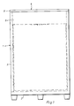
- the box structure is generally designed 1 and said structure which is made of foamed plastic preferably acrilonitrile-butadiene-styrene-plastic, includes a bottom 2 and side walls 3 or the like self-supporting heat insulating material.
- the bottom or base 2 of the box structure can be a standard pallet of so called Euro-type entirely made of foamed plastic and the wall sections may be secured to the base in any suitable way.
- the box structure may also have a lining of cardboard, plastic sheet material or the like.
- the top structure generally designed 4 is also made of foamed or cellular plastic such as acrylonitrile-butadiene-styrene plastic and is designed so it can be inserted into and be supported by the top end of the box structure.
- a protruding flange like projection 5 is intended to rest against the upper edge of the box structure walls 3.
- the top structure consist of a block like body 6 with a number of internal cavities 7 and a gas flow controlling device 8 is to be found at the centre thereof.
- the block like body includes a top part 9 with parallel upper and lower sides.
- the outer edges are step-wise arranged to form the outer flange 5 intended to rest against the upper edge of the box structure walls 3 and a lower cut out 11 intended to engage a lower part 11 as described below.
- a circular opening 12 At the center of the top part 9 there is a circular opening 12 having a cut out 13 at its upper end.
- the lower part 11 of the body may be formed in one piece and may also - if sufficiently large forming machines are not available - be formed as four separate triangular pieces subsequently joined. Lines x indicate joints between four such pieces.
- the lower part 11 has four triangular cavity forming recesses 15 separated by walls 16 and a hub-like centre portion 17.
- the upper edge of the outer walls 16′ of the lower part 11 is to engage the cut out 10 of the top part 9, whereas the top side of the recess separating walls 16 engage the lower side of the top part 9.
- the centre portion 17 has a bore 18, which extends through the lower part 11 to the underside thereof.
- the lower edge of the bore is bevelled and four V-shaped grooves 19 extend diagonally towards the outer corners of the underside.
- each of the recesses 15 From the inner corner of each of the recesses 15 to the bore 18 extends a U-shaped groove (not shown) each adapted to receive and position a pipe as described below.
- a plug 20 having a peripheral flange 21 engaging the cut-out 13 at the upper end of the circular opening 12 of the top part 9 is insertable into said opening so as to meet the upper side of the hub like centre portion 17. Before the plug 20 is inserted the inner corners of each of the recesses or cavities are accessible through the circular opening 12.
- the gas flow control device 8 includes an outer sleeve 22 having bottom and top walls 23 and 24 respectively, the sleeve being formed by two separate pieces 22′ and 22 ⁇ joined at a snap action V-joint 25; four radially oriented pipes 26 attached to the outer sleeve at holes 27 therein; an internal flange 28 attached to the inside of the sleeve 22 below the holes and pipes 27 and 26 respectively; an inner sleeve 29 open at both ends and secured to the inner edge of the flange 28 and extending upwardly above the holes 27 of the outer sleeve but terminating remote from the outer sleeve top wall 24.
- the bottom wall 23 extends radially beyond the outside of the outer sleeve forming an abutment for a circular disc 30 and perforations 31 are made through the outer sleeve adjacent the bottom wall thereof.
- top part 9 and the lower part 11 may be glued together.
- the lower part 11 consists of four separately formed pieces also such pieces may be glued together.
- lower part pieces are also mechanically held together by the pipes 22 engaging the top of each centre portion 17 and the disc 30 engaging the underside. Pins attached to the disc and pressing into the bottom material further ensures a good mechanical contact.
- the cavities 7 are filled to a predetermined level with liquid gas, e.g. nitrogen through the inner corner portions of the cavities accessible through the central opening 12.
- liquid gas e.g. nitrogen
- the filling preferably is made with a four barrelled gravity funnel or mouthpiece.
- the plug 20 is inserted thereby sealing the cavities 7 from the exterior. Gas evaporating from the contents of the cavities now escapes through the pipes 26 into the chamber 32 defined by the inside of the outer sleeve 22, the flange 28 and the inner sleeve 29 and from this chamber over the upper edge of the inner sleeve 29 downwardly through same and out via the perforations 31 to be radially channelled along the V-grooves 19 downwardly partly covered by the disc 30.
- the rate of evaporation is in per se way determined by the thickness of the insulation and the duration of the transport determines the volume liquid gas necessary.
- the simplicity of the construction using non-pressurized liquid gas makes it also possible to re-fill the cavities during the transport by removing the plug and pouring liquid into the cavities.
Landscapes
- Engineering & Computer Science (AREA)
- Mechanical Engineering (AREA)
- Chemical & Material Sciences (AREA)
- Combustion & Propulsion (AREA)
- Physics & Mathematics (AREA)
- Thermal Sciences (AREA)
- General Engineering & Computer Science (AREA)
- Packages (AREA)
- Casting Or Compression Moulding Of Plastics Or The Like (AREA)
Priority Applications (6)
| Application Number | Priority Date | Filing Date | Title |
|---|---|---|---|
| US07/083,817 US4794761A (en) | 1987-08-11 | 1987-08-11 | Top structure for cold or freeze transport container |
| ES198888850317T ES2013699T3 (es) | 1988-09-20 | 1988-09-20 | Estructura de tapa para contenedores para el transporte de mercancias frias y congeladas. |
| EP88850317A EP0359892B1 (de) | 1988-09-20 | 1988-09-20 | Deckelstruktur für Kühl- und Gefriertransportbehälter |
| AT88850317T ATE86379T1 (de) | 1988-09-20 | 1988-09-20 | Deckelstruktur fuer kuehl- und gefriertransportbehaelter. |
| DE8888850317T DE3878907T2 (de) | 1988-09-20 | 1988-09-20 | Deckelstruktur fuer kuehl- und gefriertransportbehaelter. |
| DE198888850317T DE359892T1 (de) | 1988-09-20 | 1988-09-20 | Deckelstruktur fuer kuehl- und gefriertransportbehaelter. |
Applications Claiming Priority (1)
| Application Number | Priority Date | Filing Date | Title |
|---|---|---|---|
| EP88850317A EP0359892B1 (de) | 1988-09-20 | 1988-09-20 | Deckelstruktur für Kühl- und Gefriertransportbehälter |
Publications (2)
| Publication Number | Publication Date |
|---|---|
| EP0359892A1 true EP0359892A1 (de) | 1990-03-28 |
| EP0359892B1 EP0359892B1 (de) | 1993-03-03 |
Family
ID=8200671
Family Applications (1)
| Application Number | Title | Priority Date | Filing Date |
|---|---|---|---|
| EP88850317A Expired - Lifetime EP0359892B1 (de) | 1987-08-11 | 1988-09-20 | Deckelstruktur für Kühl- und Gefriertransportbehälter |
Country Status (4)
| Country | Link |
|---|---|
| EP (1) | EP0359892B1 (de) |
| AT (1) | ATE86379T1 (de) |
| DE (2) | DE3878907T2 (de) |
| ES (1) | ES2013699T3 (de) |
Cited By (1)
| Publication number | Priority date | Publication date | Assignee | Title |
|---|---|---|---|---|
| CN119190644A (zh) * | 2024-10-18 | 2024-12-27 | 中国长江三峡集团有限公司 | 一种具有降温功能的电解液流储液罐 |
Citations (5)
| Publication number | Priority date | Publication date | Assignee | Title |
|---|---|---|---|---|
| US1865155A (en) * | 1928-03-12 | 1932-06-28 | American Thermos Bottle Co | Refrigerating device |
| DE3003987A1 (de) * | 1980-02-04 | 1981-08-13 | Messer Griesheim Gmbh, 6000 Frankfurt | Mit einer kuehleinrichtung versehener kleincontainer |
| US4561262A (en) * | 1983-07-11 | 1985-12-31 | Ilsbo Industrier Ab | Top structure |
| GB2163538A (en) * | 1984-07-03 | 1986-02-26 | Peter Frank Goodall | A small transportable container for chilled or frozen products or for products requiring controlled atmospheres or environments |
| US4794761A (en) * | 1987-08-11 | 1989-01-03 | Benny Fredrixon | Top structure for cold or freeze transport container |
-
1988
- 1988-09-20 DE DE8888850317T patent/DE3878907T2/de not_active Expired - Fee Related
- 1988-09-20 EP EP88850317A patent/EP0359892B1/de not_active Expired - Lifetime
- 1988-09-20 ES ES198888850317T patent/ES2013699T3/es not_active Expired - Lifetime
- 1988-09-20 DE DE198888850317T patent/DE359892T1/de active Pending
- 1988-09-20 AT AT88850317T patent/ATE86379T1/de not_active IP Right Cessation
Patent Citations (5)
| Publication number | Priority date | Publication date | Assignee | Title |
|---|---|---|---|---|
| US1865155A (en) * | 1928-03-12 | 1932-06-28 | American Thermos Bottle Co | Refrigerating device |
| DE3003987A1 (de) * | 1980-02-04 | 1981-08-13 | Messer Griesheim Gmbh, 6000 Frankfurt | Mit einer kuehleinrichtung versehener kleincontainer |
| US4561262A (en) * | 1983-07-11 | 1985-12-31 | Ilsbo Industrier Ab | Top structure |
| GB2163538A (en) * | 1984-07-03 | 1986-02-26 | Peter Frank Goodall | A small transportable container for chilled or frozen products or for products requiring controlled atmospheres or environments |
| US4794761A (en) * | 1987-08-11 | 1989-01-03 | Benny Fredrixon | Top structure for cold or freeze transport container |
Cited By (1)
| Publication number | Priority date | Publication date | Assignee | Title |
|---|---|---|---|---|
| CN119190644A (zh) * | 2024-10-18 | 2024-12-27 | 中国长江三峡集团有限公司 | 一种具有降温功能的电解液流储液罐 |
Also Published As
| Publication number | Publication date |
|---|---|
| DE359892T1 (de) | 1990-07-26 |
| ES2013699A4 (es) | 1990-06-01 |
| DE3878907T2 (de) | 1993-06-17 |
| ATE86379T1 (de) | 1993-03-15 |
| DE3878907D1 (de) | 1993-04-08 |
| ES2013699T3 (es) | 1993-08-01 |
| EP0359892B1 (de) | 1993-03-03 |
Similar Documents
| Publication | Publication Date | Title |
|---|---|---|
| RU2192589C2 (ru) | Изолированный транспортный контейнер | |
| US4498312A (en) | Method and apparatus for maintaining products at selected temperatures | |
| US6457323B1 (en) | Relative humidity-controlled isothermal container for transporting perishable goods at different temperatures | |
| US3678703A (en) | Cold storage carton | |
| JP2599802B2 (ja) | 製品を0゜c又はこれに近い所期の温度に維持する方法及びこのためのコンテナ | |
| CA2207445A1 (en) | Insulated storage/transport container for perishables | |
| US5218923A (en) | Container for storage and/or shipment of live lobsters | |
| US4794761A (en) | Top structure for cold or freeze transport container | |
| US6182465B1 (en) | Two-piece cooler assembly | |
| US2409279A (en) | Refrigeration apparatus | |
| FI84042C (fi) | Transport- och lagringsbehaollare foer kylvaror. | |
| ES2201633T3 (es) | Caja para productos a mantener frios y uso de tal caja. | |
| EP0359892B1 (de) | Deckelstruktur für Kühl- und Gefriertransportbehälter | |
| US4561262A (en) | Top structure | |
| KR102319485B1 (ko) | 친환경 포장박스 | |
| EP0153326B1 (de) | Deckelstruktur für gekühltes transportfach | |
| KR101513214B1 (ko) | 발포폴리스티렌 포장상자 | |
| JPS5911900Y2 (ja) | 生鮮物の低温輸送用容器 | |
| JPS63307075A (ja) | 生鮮物輸送容器及びそれを用いた生鮮物輸送方法 | |
| JPH0433251Y2 (de) | ||
| KR19990007741U (ko) | 냉장용 포장상자 | |
| JPH0343188Y2 (de) | ||
| JPH0340778Y2 (de) | ||
| KR20240123489A (ko) | 냉동박스 및 냉동박스 이용방법 | |
| JPH04262736A (ja) | 生鮮品等の収容法 |
Legal Events
| Date | Code | Title | Description |
|---|---|---|---|
| PUAI | Public reference made under article 153(3) epc to a published international application that has entered the european phase |
Free format text: ORIGINAL CODE: 0009012 |
|
| 17P | Request for examination filed |
Effective date: 19890913 |
|
| AK | Designated contracting states |
Kind code of ref document: A1 Designated state(s): AT BE CH DE ES FR GB IT LI NL SE |
|
| TCNL | Nl: translation of patent claims filed | ||
| ITCL | It: translation for ep claims filed |
Representative=s name: ORGANIZZAZIONE D'AGOSTINI |
|
| TCAT | At: translation of patent claims filed | ||
| EL | Fr: translation of claims filed | ||
| DET | De: translation of patent claims | ||
| 17Q | First examination report despatched |
Effective date: 19910620 |
|
| GRAA | (expected) grant |
Free format text: ORIGINAL CODE: 0009210 |
|
| AK | Designated contracting states |
Kind code of ref document: B1 Designated state(s): AT BE CH DE ES FR GB IT LI NL SE |
|
| REF | Corresponds to: |
Ref document number: 86379 Country of ref document: AT Date of ref document: 19930315 Kind code of ref document: T |
|
| REF | Corresponds to: |
Ref document number: 3878907 Country of ref document: DE Date of ref document: 19930408 |
|
| ITF | It: translation for a ep patent filed | ||
| ET | Fr: translation filed | ||
| REG | Reference to a national code |
Ref country code: ES Ref legal event code: FG2A Ref document number: 2013699 Country of ref document: ES Kind code of ref document: T3 |
|
| PLBE | No opposition filed within time limit |
Free format text: ORIGINAL CODE: 0009261 |
|
| STAA | Information on the status of an ep patent application or granted ep patent |
Free format text: STATUS: NO OPPOSITION FILED WITHIN TIME LIMIT |
|
| 26N | No opposition filed | ||
| EAL | Se: european patent in force in sweden |
Ref document number: 88850317.4 |
|
| PGFP | Annual fee paid to national office [announced via postgrant information from national office to epo] |
Ref country code: GB Payment date: 19960913 Year of fee payment: 9 |
|
| PGFP | Annual fee paid to national office [announced via postgrant information from national office to epo] |
Ref country code: NL Payment date: 19960930 Year of fee payment: 9 Ref country code: ES Payment date: 19960930 Year of fee payment: 9 Ref country code: AT Payment date: 19960930 Year of fee payment: 9 |
|
| PGFP | Annual fee paid to national office [announced via postgrant information from national office to epo] |
Ref country code: BE Payment date: 19961003 Year of fee payment: 9 |
|
| PG25 | Lapsed in a contracting state [announced via postgrant information from national office to epo] |
Ref country code: GB Free format text: LAPSE BECAUSE OF NON-PAYMENT OF DUE FEES Effective date: 19970920 Ref country code: AT Free format text: LAPSE BECAUSE OF NON-PAYMENT OF DUE FEES Effective date: 19970920 |
|
| PG25 | Lapsed in a contracting state [announced via postgrant information from national office to epo] |
Ref country code: ES Free format text: LAPSE BECAUSE OF THE APPLICANT RENOUNCES Effective date: 19970922 |
|
| PG25 | Lapsed in a contracting state [announced via postgrant information from national office to epo] |
Ref country code: BE Free format text: LAPSE BECAUSE OF NON-PAYMENT OF DUE FEES Effective date: 19970930 |
|
| BERE | Be: lapsed |
Owner name: MC TRADING A.G. Effective date: 19970930 |
|
| PG25 | Lapsed in a contracting state [announced via postgrant information from national office to epo] |
Ref country code: NL Free format text: LAPSE BECAUSE OF NON-PAYMENT OF DUE FEES Effective date: 19980401 |
|
| GBPC | Gb: european patent ceased through non-payment of renewal fee |
Effective date: 19970920 |
|
| NLV4 | Nl: lapsed or anulled due to non-payment of the annual fee |
Effective date: 19980401 |
|
| PGFP | Annual fee paid to national office [announced via postgrant information from national office to epo] |
Ref country code: DE Payment date: 19980916 Year of fee payment: 11 |
|
| PGFP | Annual fee paid to national office [announced via postgrant information from national office to epo] |
Ref country code: FR Payment date: 19980918 Year of fee payment: 11 |
|
| PGFP | Annual fee paid to national office [announced via postgrant information from national office to epo] |
Ref country code: SE Payment date: 19980921 Year of fee payment: 11 |
|
| PGFP | Annual fee paid to national office [announced via postgrant information from national office to epo] |
Ref country code: CH Payment date: 19980922 Year of fee payment: 11 |
|
| PG25 | Lapsed in a contracting state [announced via postgrant information from national office to epo] |
Ref country code: SE Free format text: THE PATENT HAS BEEN ANNULLED BY A DECISION OF A NATIONAL AUTHORITY Effective date: 19990929 |
|
| PG25 | Lapsed in a contracting state [announced via postgrant information from national office to epo] |
Ref country code: LI Free format text: LAPSE BECAUSE OF NON-PAYMENT OF DUE FEES Effective date: 19990930 Ref country code: CH Free format text: LAPSE BECAUSE OF NON-PAYMENT OF DUE FEES Effective date: 19990930 |
|
| EUG | Se: european patent has lapsed |
Ref document number: 88850317.4 |
|
| REG | Reference to a national code |
Ref country code: CH Ref legal event code: PL |
|
| PG25 | Lapsed in a contracting state [announced via postgrant information from national office to epo] |
Ref country code: FR Free format text: LAPSE BECAUSE OF NON-PAYMENT OF DUE FEES Effective date: 20000531 |
|
| PG25 | Lapsed in a contracting state [announced via postgrant information from national office to epo] |
Ref country code: DE Free format text: LAPSE BECAUSE OF NON-PAYMENT OF DUE FEES Effective date: 20000701 |
|
| REG | Reference to a national code |
Ref country code: FR Ref legal event code: ST |
|
| REG | Reference to a national code |
Ref country code: ES Ref legal event code: FD2A Effective date: 20001009 |
|
| PG25 | Lapsed in a contracting state [announced via postgrant information from national office to epo] |
Ref country code: IT Free format text: LAPSE BECAUSE OF NON-PAYMENT OF DUE FEES;WARNING: LAPSES OF ITALIAN PATENTS WITH EFFECTIVE DATE BEFORE 2007 MAY HAVE OCCURRED AT ANY TIME BEFORE 2007. THE CORRECT EFFECTIVE DATE MAY BE DIFFERENT FROM THE ONE RECORDED. Effective date: 20050920 |