EP0359903B1 - Koffer - Google Patents
Koffer Download PDFInfo
- Publication number
- EP0359903B1 EP0359903B1 EP89108243A EP89108243A EP0359903B1 EP 0359903 B1 EP0359903 B1 EP 0359903B1 EP 89108243 A EP89108243 A EP 89108243A EP 89108243 A EP89108243 A EP 89108243A EP 0359903 B1 EP0359903 B1 EP 0359903B1
- Authority
- EP
- European Patent Office
- Prior art keywords
- case
- profiles
- profile
- suitcase
- corners
- Prior art date
- Legal status (The legal status is an assumption and is not a legal conclusion. Google has not performed a legal analysis and makes no representation as to the accuracy of the status listed.)
- Expired - Lifetime
Links
Images


Classifications
-
- A—HUMAN NECESSITIES
- A45—HAND OR TRAVELLING ARTICLES
- A45C—PURSES; LUGGAGE; HAND CARRIED BAGS
- A45C5/00—Rigid or semi-rigid luggage
- A45C5/02—Materials therefor
Definitions
- the invention relates to a suitcase according to the preamble of the main claim.
- Such cases as is known for example from US-A-770 312, have three levels, in which profile strips run, which form a frame for the individual plates. These levels are formed on the one hand by the two outer profiles, which run around the bottom or lid of the case as the top or bottom of the three levels, and by two middle profiles, which form the middle level and adjoin one another when the case is closed.
- a suitcase which consists of an upper and lower part with a frame for holding the walls, the middle frame each consisting of a single piece.
- the formation of the corner areas of these frames is not explained in detail. So that these frames have the necessary stability, they must have a certain thickness, so that these frames cannot be easily bent by 90 °. Such bends are particularly difficult when it comes to profile strips.
- the invention has for its object to provide a case that has high stability middle profiles that also create high stability in the corner area.
- the one-piece circumferential center profile with rounded edges means that it is also more stable than a one-piece circumferential center profile, in which the edges are angular, since the material of the center profile is structurally heavily loaded and accordingly little with this strong deformation Has load reserves.
- the recess in the area of the rounded edge of the case, which is directed towards the inside of the case later, ensures that a larger space is created which faces the inside of the case and which a special insert fills can, so that here, in contrast to the kinked center profiles, compensation for the reduction in cross-section can take place.
- the fact that the case corners are formed from special molded parts which fix the outer profiles and the vertical profile strips with the aid of tenon joints ensures good stability and a secure fit of the individual profile elements on the respective case corner.
- Caps which are inserted inside the eight case corners, offer an advantageous appearance and, in particular, good cleaning options, so that no badly accessible edges or hollows are created where profile elements abut against each other.
- the stability of the entire case can be increased by gluing the individual components of the case together.
- Fig. 1 it can be seen that the case consists of individual straight plates, namely a cover plate 1, which is assigned a similar but not shown bottom plate opposite. Furthermore, from a front plate 2, which has an upper section 2a and a lower section 2b and to which similar back plates are assigned. Finally, the case has two side plates 3, one of which is shown, the upper section of which is labeled 3a and the lower section of which is labeled 3b.
- the plates 1, 2 and 3 of the case are connected to one another by profile strips, with outer profiles 4 each adjoining the cover plate 1 and the base plate, not shown, while two middle profiles 5 abut each other in the middle of the case, which border the two half-shells of the case.
- case corners 7 are designed as one-piece plastic molded parts and which partially cover the elements of the outer profile 4.
- Cams 8 are formed on the case corners 7 pointing upwards or downwards, the cams 8 only extending over half of the top and bottom of a case corner 7. Due to this design and due to the different orientation of the cams 8 on the upward or downward-facing case corners 7, a stackability of several cases is effected, in which the cams 8 of different cases make it difficult or prevent the individual cases stacked on top of one another from slipping.
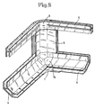
- FIG. 1 An edge of the case of FIG. 1 is designated in more detail in FIG. 2, the base plate and the lower sections 2a of the front plate 2 and 3a of the side plate 3 not being shown.
- the vertical profile bar 6 forms the edge of the case and receives at its upper end a one-piece insert 9, which in turn defines the rounded area of the central profile 5.
- This rounded area of the central profile 5 has a recess 19, so that only the outward-facing wall remains of the essentially H-shaped profile cross-section in the area of the case edge.
- the insert 9 fills out the removed cross-sectional part of the central profile 5 and, moreover, fixes the two ends, at which the cross-section is still H-shaped, by means of a pin connection, so that, in this edge region, the stability of the profile bar forming the central profile 5 is scarcely is reduced or impaired.
- pins 10 and 11 can be clearly seen, with which the insert 9 extends into the central profile 5 and into the vertical profile bar 6.
- the pin 11 is formed in three parts, on the one hand in the middle channel and on the other hand to be able to extend into the two outer grooves of the profile bar 6.
- the case corner 7 has pins which are similar to the pins 11 of the insert 9 and also serve to fix the vertical profile bar 6. Furthermore, the case corner 7 has pins 12, on which the elements of the outer profile 4 are inserted. To increase the stability, these pins 12 are arranged at a distance from an outer surface 14 of the case corner 7, so that the outer profiles 4 are not only fixed on the pin 12, but also between the pin 12 and the outer surface 14. This arrangement makes the optical Appearance improved in that an always clean and seamless connection of the outer profiles 4 to the case corners 7 is achieved.
- this trough is covered by a cap 15, so that, as can be seen particularly from FIG. 2, a flush closure and connection of the individual profile elements in the area of the case corner 7 is reached.
- the case shown and described gives the continuous center profile 5 a very good stability, which can be further increased by the fact that the pins 10, 11 and 12 are dimensioned so that they fix the associated profile elements slightly jamming, so that thereby a secure bond individual frame parts is effected with each other.
- the plates 1, 2 and 3 defined later in the frame further increase the stability of the case.
- the individual frame parts can be glued to one another or to the plates, which brings about a further gain in stability, particularly in the case of larger suitcases.
- the case as a whole (FIG. 1) appears flatter and less bulbous than a case with the same dimensions however round outer profiles.
Landscapes
- Chemical & Material Sciences (AREA)
- Engineering & Computer Science (AREA)
- Materials Engineering (AREA)
- Purses, Travelling Bags, Baskets, Or Suitcases (AREA)
Description
- Die Erfindung bezieht sich auf einen Koffer gemäß dem Oberbegriff des Hauptanspruches.
- Koffer, die beispielsweise Platten aus Aluminium bzw. aluminiumkaschierte Holzplatten verwenden und dann unter dem Begriff Aluminiumkoffer bekannt sind, dienen beispielsweise der Aufnahme hochwertiger Geräte, wie Foto- oder Videoausrüstungen. Im Gegensatz zu den ebenfalls erhältlichen weicheren Tragetaschen sollen sie in erster Linie einen robusten Schutz für die hochwertigen und teuren Geräte darstellen.
- Derartige Koffer, wie z.B. aus US-A-770 312 bekannt ist, weisen drei Ebenen auf, in denen Profilleisten verlaufen, welche einen Rahmen für die einzelnen Platten bilden. Diese Ebenen werden zum einen durch die beiden Außenprofile gebildet, welche um den Boden bzw. Deckel des Koffers verlaufen als oberste bzw. unterste der drei Ebenen, sowie durch zwei Mittelprofile, welche die mittlere Ebene bilden und bei geschlossenem Koffer aneinander angrenzen.
- Aus der DE-C-827 229 ist ein Koffer bekannt, der aus Ober- und Unterteil besteht mit Rahmen zum Halten der Wände, wobei die Mittelrahmen je aus einem einzigen Stück bestehen. Die Ausbildung der Eckbereiche dieser Rahmen ist nicht näher erläutert. Damit diese Rahmen aber die nötige Stabilität aufweisen, müssen sie eine gewisse Dicke besitzen, so daß diese Rahmen dann nicht ohne weiteres um 90° gebogen werden können. Insbesondere sind derartige Biegungen dann schwierig, wenn es sich um Profilleisten handelt.
- Der Erfindung liegt die Aufgabe zugrunde, einen Koffer zu schaffen, der eine hohe Stabilität aufweisende Mittelprofile besitzt, die auch im Eckbereich eine hohe Stabilität schaffen.
- Diese der Erfindung zugrundeliegende Aufgabe wird durch die Lehre des Hauptanspruches gelöst.
- Mit anderen Worten ausgedrückt wird durch das einteilig umlaufende Mittelprofil mit gerundeten Kanten erreicht, daß dieses auch stabiler ist als ein einteilig umlaufendes Mittelprofil, bei welchem die Kanten eckig ausgebildet sind, da bei dieser starken Verformung der Werkstoff des Mittelprofils gefügemäßig stark belastet wird und dementsprechend wenig Belastungsreserven aufweist. Durch die zum späteren Kofferinneren hin gerichtete Ausnehmung im Bereich der gerundeten Kofferkante wird erreicht, daß ein größerer, zum Kofferinneren weisender Freiraum geschaffen wird, den ein spezieller Einsatz ausfüllen kann, so daß hier im Gegensatz zu den geknickten Mittelprofilen ein Ausgleich für die Querschnittsverringerung erfolgen kann. Dadurch, daß die Kofferecken aus speziellen Formteilen ausgebildet sind, die die Außenprofile sowie die senkrechten Profilleisten mit Hilfe von Zapfverbindungen festlegen, wird eine gute Stabilität und ein sicherer Sitz der einzelnen Profilelemente an der jeweiligen Kofferecke gewährleistet.
- Vorteilhafte Ausgestaltungen sind in den Unteransprüchen erläutert.
- Durch eine Ausführung der Außenprofile als winklig gekantete und nicht gerundet verlaufende Profile wird eine zusätzliche Stabilität dieser Profile erreicht und darüber hinaus dem Koffer ein eleganteres und flacheres Aussehen verliehen als bei der Verwendung von gerundeten Außenprofilen.
- Ein vorteilhaftes Erscheinungsbild und insbesondere gute Reinigungsmöglichkeiten bieten Kappen, welche innen in die acht Kofferecken eingesetzt sind, um dort, wo jeweils Profilelemente aneinander anstoßen, keine schlecht erreichbaren Kanten oder Mulden entstehen zu lassen.
- Schließlich kann die Stabilität des gesamten Koffers dadurch gesteigert werden, daß die einzelnen Bauteile des Koffers miteinander verklebt werden.
- Anhand der Zeichnungen wird ein erfindungsgemäßer Koffer dargestellt. Dabei zeigt
- Fig. 1
- eine schaubildliche Gesamtansicht des Koffers,
- Fig. 2
- eine Kofferkante vom Kofferinneren her gesehen und
- Fig. 3
- die Kofferkante von Fig. 2, wobei die einzelnen Bauteile auseinandergezogen dargestellt sind.
- In Fig. 1 ist erkennbar, daß der Koffer aus einzelnen geraden Platten besteht, nämlich aus einer Deckelplatte 1, der eine gleichartige jedoch nicht dargestellte Bodenplatte gegenüberliegend zugeordnet ist. Weiterhin aus einer Frontplatte 2, die einen oberen Abschnitt 2a und einen unteren Abschnitt 2b aufweist und der gleichartige Rückenplatten zugeordnet sind. Schließlich weist der Koffer zwei Seitenplatten 3 auf, von denen eine dargestellt ist, deren oberer Abschnitt mit 3a und deren unterer Abschnitt mit 3b bezeichnet sind.
- Die Platten 1, 2 und 3 des Koffers sind durch Profilleisten miteinander verbunden, wobei an die Deckelplatte 1 sowie die nicht dargestellte Bodenplatte jeweils Außenprofile 4 angrenzen, während in der Mitte des Koffers zwei Mittelprofile 5 aneinander anstoßen, welche die beiden Halbschalen des Koffers einfassen.
- Neben diesen waagerecht verlaufenden Profilen 4 und 5 werden die Platten 1 bis 3 des Koffers weiterhin durch senkrechte Profilleisten 6 verbunden, die jeweils senkrecht zwischen zwei übereinanderliegenden Kofferecken verlaufen.
- Im Bereich der Kofferecken werden die jeweils zwei Elemente des Außenprofils 4 mit der senkrechten Profilleiste 6 durch Kofferecken 7 verbunden, die als einteilige Kunststofformteile ausgebildet sind und die die Elemente des Außenprofils 4 teilweise überdecken. An die Kofferecken 7 sind nach oben bzw. nach unten weisend Nocken 8 angeformt, wobei sich die Nocken 8 jeweils nur über die Hälfte der Ober- bzw. Unterseite einer Kofferecke 7 erstrecken. Aufgrund dieser Ausbildung und aufgrund der unterschiedlichen Ausrichtung der Nocken 8 an den nach oben bzw. den nach unten gerichteten Kofferecken 7 wird eine Stapelbarkeit mehrerer Koffer übereinander bewirkt, bei der die Nocken 8 verschiedener Koffer ein Verrutschen der einzelnen übereinandergestapelten Koffer erschweren oder verhindern.
- In Fig. 2 ist eine Kante des Koffers von Fig. 1 näher bezeichnet, wobei die Bodenplatte sowie die unteren Abschnitte 2a der Frontplatte 2 sowie 3a der Seitenplatte 3 nicht dargestellt sind. Die senkrechte Profilleiste 6 bildet die Kofferkante und nimmt an ihrem oberen Ende einen einteiligen Einsatz 9 auf, welcher wiederum den gerundeten Bereich des Mittelprofils 5 festlegt. Dieser gerundete Bereich des Mittelprofils 5 weist eine Ausnehmung 19 auf, so daß von dem im wesentlichen H-förmigen Profilquerschnitt im Bereich der Kofferkante lediglich die nach außen gerichtete Wand stehen bleibt.
- Durch den sanft gerundeten Verlauf dieser Kante ist das Gefüge des Profilmaterials in diesem Biegebereich nicht so stark belastet wie es beispielsweise beim Knicken eines solchen Profils um 90° der Fall wäre. Weiterhin füllt der Einsatz 9 den entfernten Querschnittsteil des Mittelprofils 5 aus und legt darüber hinaus die beiden Enden, an denen der Querschnitt noch H-förmig ist, durch eine Zapfenverbindung fest, so daß ,in diesem Kantenbereich die Stabilität der das Mittelprofil 5 bildende Profilleiste kaum verringert oder beeinträchtigt wird.
- Insbesondere aus Fig. 3 ist die Ausbildung von Zapfen 10 und 11 deutlich erkennbar, mit denen sich der Einsatz 9 in das Mittelprofil 5 erstreckt sowie in die senkrechte Profilleiste 6. Der Zapfen 11 ist dabei dreiteilig ausgebildet, um sich einerseits in den mittleren Kanal und andererseits in die beiden äußeren Nuten der Profilleiste 6 erstrecken zu können.
- Die Kofferecke 7 weist Zapfen auf, die den Zapfen 11 des Einsatzes 9 ähnlich sind und ebenfalls dazu dienen, die senkrechte Profilleiste 6 festzulegen. Weiterhin weist die Kofferecke 7 Zapfen 12 auf, auf welche die Elemente des Außenprofils 4 gesteckt werden. Zur Vergrößerung der Stabilität sind diese Zapfen 12 im Abstand von einer Außenfläche 14 der Kofferecke 7 angeordnet, so daß die Außenprofile 4 nicht nur auf den Zapfen 12 festgelegt werden, sondern auch zwischen den Zapfen 12 und der Außenfläche 14. Durch diese Anordnung wird das optische Erscheinungsbild insofern verbessert, als ein stets sauberer und fugenloser Anschluß der Außenprofile 4 an die Kofferecken 7 erzielt wird.
- Um bei einem zusammengefügten Verbund der in Fig. 3 dargestellten einzelnen Elemente nicht im Bereich der Kofferecke 7 eine schlecht zugängliche Mulde zu schaffen, wird diese Mulde durch eine Kappe 15 abgedeckt, so daß, wie insbesondere aus Fig. 2 ersichtlich ist, ein bündiger Abschluß und Anschluß der einzelnen Profilelemente im Bereich der Kofferecke 7 erreicht wird. Somit wird verhindert, daß im Bereich der Kofferecke 7 die senkrechte Profilleiste 6 und das Außenprofil 4 scharfkantige Möglichkeiten zur Beschädigung der Geräte im Kofferinnern schaffen, daß die Reinigung in dieser Ecke erschwert wird oder auch daß Kleinteile wie Schrauben od. dgl. in einer derartigen Mulde unerreichbar verschwinden.
- Dem dargestellten und beschriebenen Koffer verleiht das durchlaufende Mittelprofil 5 eine sehr gute Stabilität, die weiterhin dadurch gesteigert werden kann, daß die Zapfen 10, 11 und 12 so bemessen sind, daß sie die zugehörigen Profilelemente leicht klemmend festlegen, so daß dadurch ein sicherer Verbund der einzelnen Rahmenteile untereinander bewirkt wird. Die später in dem Rahmen festgelegten Platten 1, 2 und 3 bewirken eine weitere Verstärkung der Stabilität des Koffers. Zusätzlich können die einzelnen Rahmenteile miteinander oder mit den Platten verklebt werden, was insbesondere bei größeren Koffern einen weiteren Stabilitätsgewinn bewirkt .
- Die Außenprofile 4 weisen, wie insbesondere auch aus den Fig. 2 und 3 ersichtlich ist, einen winkligen Querschnitt auf, so daß die Stabilität gegenüber runden Querschnitten verbessert wird. Darüber hinaus wirkt der Koffer insgesamt (Fig. 1) flacher und weniger bauchig als ein Koffer mit gleichen Abmessungen, jedoch runden Außenprofilen.
Claims (5)
- Koffer aus mehreren Einzelplatten (1, 2, 3), die durch Profilleisten (4, 5) zu zwei Halbschalen verbunden sind, wobei die Profilleisten jeder Halbschale ein Außen- (4) und ein Mittelprofil (5) bilden, wobei einteilig umlaufende Mittelprofile (5) vorgesehen sind, dadurch gekennzeichnet, dass die Mittelprofile im Bereich der Kofferkanten gerundet verlaufen und zum Kofferinneren weisende Ausnehmungen (19) aufweisen, wobei diese Ausnehmungen (19) Einsätze (9) aufnehmen, die jeweils mit den angrenzenden Querschnitten des Mittelprofils (5) sowie mit einer senkrechten Profilleiste (6) verbunden sind und aus separaten Formteilen gebildete Kofferecken (7) vorgesehen sind, die durch Zapfverbindungen mit den Außenprofilen (4) und den senkrechten Profilleisten (6) verbunden sind, wobei die Kofferecken (7) die Außenprofile (4) teilweise überdecken.
- Koffer nach Anspruch 1, gekennzeichnet durch im Querschnitt winklige Profilleisten in den Außenprofilen (4).
- Koffer nach Anspruch 1 oder 2, gekennzeichnet durch Kappen (15), welche innen in die Kofferecken (7) eingesetzt sind und bündig an die zum Kofferinneren gerichteten Oberflächen der Außenprofile (4) und der senkrechten Profilleisten (6) anschließen.
- Koffer nach einem der vorhergehenden Ansprüche, gekennzeichnet durch miteinander verklebte einzelne Elemente (Platten 1, 2, 3), Außen- (4) und Mittelprofile (5), senkrechte Profilleisten (6), Kofferecken (7), Einsätze (9), Kappen (15))des Koffers.
- Koffer nach einem der vorhergehenden Ansprüche, gekennzeichnet durch Nocken (8), die an den Kofferecken (7) angeformt sind und sich über die Hälfte der Ober- bzw. Unterseite einer Kofferecke (7) erstrecken.
Priority Applications (1)
| Application Number | Priority Date | Filing Date | Title |
|---|---|---|---|
| AT89108243T ATE103475T1 (de) | 1988-09-17 | 1989-05-08 | Koffer. |
Applications Claiming Priority (2)
| Application Number | Priority Date | Filing Date | Title |
|---|---|---|---|
| DE3831655A DE3831655A1 (de) | 1988-09-17 | 1988-09-17 | Koffer |
| DE3831655 | 1988-09-17 |
Publications (3)
| Publication Number | Publication Date |
|---|---|
| EP0359903A2 EP0359903A2 (de) | 1990-03-28 |
| EP0359903A3 EP0359903A3 (de) | 1991-02-27 |
| EP0359903B1 true EP0359903B1 (de) | 1994-03-30 |
Family
ID=6363156
Family Applications (1)
| Application Number | Title | Priority Date | Filing Date |
|---|---|---|---|
| EP89108243A Expired - Lifetime EP0359903B1 (de) | 1988-09-17 | 1989-05-08 | Koffer |
Country Status (4)
| Country | Link |
|---|---|
| EP (1) | EP0359903B1 (de) |
| AT (1) | ATE103475T1 (de) |
| DE (2) | DE3831655A1 (de) |
| ES (1) | ES2051918T3 (de) |
Cited By (2)
| Publication number | Priority date | Publication date | Assignee | Title |
|---|---|---|---|---|
| DE29505668U1 (de) * | 1995-04-03 | 1996-08-08 | BWH-Koffer-, Handels- und Vermögensverwaltungsgesellschaft mbH & Co KG, 48477 Hörstel | Koffer |
| CN107087391A (zh) * | 2014-11-05 | 2017-08-22 | Gt线路有限公司 | 可运输式容器及相关生产方法 |
Families Citing this family (6)
| Publication number | Priority date | Publication date | Assignee | Title |
|---|---|---|---|---|
| DE3905494A1 (de) * | 1989-02-23 | 1990-08-30 | G S A Elektro Elektronik Baute | Behaelter |
| DE19848901C1 (de) * | 1998-10-23 | 2000-03-16 | Witte Kay Uwe | Koffer |
| US6604616B2 (en) * | 2002-01-03 | 2003-08-12 | Chun Lung Cheng | Container with multi-functional edge frame arrangement |
| GB0407629D0 (en) * | 2004-04-02 | 2004-05-05 | Landor & Hawa Int Ltd | Suitcase |
| GB2477087A (en) * | 2010-01-20 | 2011-07-27 | Landor & Hawa Int Ltd | Improved luggage construction |
| DE202015005934U1 (de) * | 2015-08-26 | 2015-10-08 | W.AG Funktion + Design GmbH | Schalenkoffer, insbesondere Hartschalenkoffer |
Family Cites Families (8)
| Publication number | Priority date | Publication date | Assignee | Title |
|---|---|---|---|---|
| US1675654A (en) * | 1923-03-03 | 1928-07-03 | Milwaukee Stamping Company | Reenforcing frame for wardrobe-trunk sections |
| DE827229C (de) * | 1948-12-24 | 1952-02-21 | Carl Kuhne | Koffer, bestehend aus Ober- und Unterteil, mit Rahmen zum Halten der Waende |
| DE6945296U (de) * | 1969-11-21 | 1970-03-05 | Heinr Huelter Jr Fa | In form eines koffers, einer buegeltasche oder dergl. ausgebildeter behaelter |
| DE7028787U (de) * | 1970-07-30 | 1970-11-12 | Rox Lederwarenfabriken Gmbh | Koffer. |
| DE7524045U (de) * | 1975-07-29 | 1975-12-04 | Graetz Kg | Nach der Faltbauweise herstellbares Gehäuse, insbesondere für Geräte der Unterhaltungselektronik oder Nachrichtentechnik |
| DE2714623C3 (de) * | 1977-04-01 | 1985-08-01 | Franz Delbrouck Gmbh, 5750 Menden | Stapelbare Steige |
| DE3511931A1 (de) * | 1985-04-01 | 1986-10-09 | Günter 8488 Erbendorf Schneider | Koffer oder aehnlicher behaelter aus zwei haelften |
| US4770312A (en) * | 1987-06-10 | 1988-09-13 | Judy O | Detachable case |
-
1988
- 1988-09-17 DE DE3831655A patent/DE3831655A1/de active Granted
-
1989
- 1989-05-08 DE DE89108243T patent/DE58907336D1/de not_active Expired - Fee Related
- 1989-05-08 ES ES89108243T patent/ES2051918T3/es not_active Expired - Lifetime
- 1989-05-08 EP EP89108243A patent/EP0359903B1/de not_active Expired - Lifetime
- 1989-05-08 AT AT89108243T patent/ATE103475T1/de active
Cited By (3)
| Publication number | Priority date | Publication date | Assignee | Title |
|---|---|---|---|---|
| DE29505668U1 (de) * | 1995-04-03 | 1996-08-08 | BWH-Koffer-, Handels- und Vermögensverwaltungsgesellschaft mbH & Co KG, 48477 Hörstel | Koffer |
| CN107087391A (zh) * | 2014-11-05 | 2017-08-22 | Gt线路有限公司 | 可运输式容器及相关生产方法 |
| CN107087391B (zh) * | 2014-11-05 | 2019-08-20 | Gt线路有限公司 | 可运输式容器及相关生产方法 |
Also Published As
| Publication number | Publication date |
|---|---|
| DE3831655C2 (de) | 1991-11-28 |
| ES2051918T3 (es) | 1994-07-01 |
| EP0359903A3 (de) | 1991-02-27 |
| ATE103475T1 (de) | 1994-04-15 |
| DE3831655A1 (de) | 1990-03-29 |
| DE58907336D1 (de) | 1994-05-05 |
| EP0359903A2 (de) | 1990-03-28 |
Similar Documents
| Publication | Publication Date | Title |
|---|---|---|
| EP0789983B1 (de) | Rahmenschenkel für ein rahmengestell eines schaltschrankes | |
| DE19536950C1 (de) | Rahmenschenkel für ein Rahmengestell eines Schaltschrankes | |
| DE68910979T2 (de) | Verbindungssystem. | |
| CH660116A5 (de) | Gestell aus mehreren profilstaeben. | |
| EP0951116A1 (de) | Rahmenschenkel für ein Rahmengestell eines Schaltschrankes | |
| DE3124391A1 (de) | Koffer | |
| EP0359903B1 (de) | Koffer | |
| DE9207859U1 (de) | Glasscheibenhalter | |
| AT395339B (de) | Scheibenhalterung zum aufhaengen von scheibenfeldern an einer traegerkonstruktion bei ganzglasfassaden und dgl. | |
| DE68907838T2 (de) | Eckverbinder. | |
| DE9407846U1 (de) | Koffer mit zwei doppelwandigen Kofferhälften, die aus thermoplastischem Kunststoff im Wege der Blasformgebung geformt sind | |
| DE9206018U1 (de) | Sectionaltor | |
| DE8910518U1 (de) | Paneele für ein Sektionaltor | |
| DE2033724C3 (de) | Zusammenlegbare Kiste | |
| DE8811817U1 (de) | Koffer | |
| EP3753857B1 (de) | Wandelement eines paletten-aufsatzrahmens und paletten-aufsatzrahmen | |
| DE2903432C2 (de) | Scharnier | |
| DE8107577U1 (de) | Rahmen aus geraden rahmenteilen und eckverbindern | |
| DE2810764A1 (de) | Chassis zur befestigung von elektromechanischen oder pneumatischen geraeten | |
| DE2645671C2 (de) | Aus einzelnen Torfelder gebildetes Deckengliedertor | |
| DE29500992U1 (de) | Zusammenfaltbarer Lager- und Transportbehälter | |
| DE9109138U1 (de) | Wand- oder Türelement und Eckelement zu dessen Herstellung | |
| DE2900001A1 (de) | Eckverbinder | |
| DE19509657A1 (de) | Fensterrahmen, insbesondere aus Kunststoff | |
| DE9303070U1 (de) | Bauelementenverbund in Form eines Daches |
Legal Events
| Date | Code | Title | Description |
|---|---|---|---|
| PUAI | Public reference made under article 153(3) epc to a published international application that has entered the european phase |
Free format text: ORIGINAL CODE: 0009012 |
|
| AK | Designated contracting states |
Kind code of ref document: A2 Designated state(s): AT BE CH DE ES FR GB IT LI NL SE |
|
| PUAL | Search report despatched |
Free format text: ORIGINAL CODE: 0009013 |
|
| AK | Designated contracting states |
Kind code of ref document: A3 Designated state(s): AT BE CH DE ES FR GB IT LI NL SE |
|
| 17P | Request for examination filed |
Effective date: 19910125 |
|
| 17Q | First examination report despatched |
Effective date: 19921125 |
|
| GRAA | (expected) grant |
Free format text: ORIGINAL CODE: 0009210 |
|
| AK | Designated contracting states |
Kind code of ref document: B1 Designated state(s): AT BE CH DE ES FR GB IT LI NL SE |
|
| PG25 | Lapsed in a contracting state [announced via postgrant information from national office to epo] |
Ref country code: SE Free format text: THE PATENT HAS BEEN ANNULLED BY A DECISION OF A NATIONAL AUTHORITY Effective date: 19940330 |
|
| REF | Corresponds to: |
Ref document number: 103475 Country of ref document: AT Date of ref document: 19940415 Kind code of ref document: T |
|
| REF | Corresponds to: |
Ref document number: 58907336 Country of ref document: DE Date of ref document: 19940505 |
|
| PG25 | Lapsed in a contracting state [announced via postgrant information from national office to epo] |
Ref country code: AT Effective date: 19940508 |
|
| ITF | It: translation for a ep patent filed | ||
| PG25 | Lapsed in a contracting state [announced via postgrant information from national office to epo] |
Ref country code: LI Effective date: 19940531 Ref country code: CH Effective date: 19940531 |
|
| ET | Fr: translation filed | ||
| GBT | Gb: translation of ep patent filed (gb section 77(6)(a)/1977) |
Effective date: 19940523 |
|
| REG | Reference to a national code |
Ref country code: ES Ref legal event code: FG2A Ref document number: 2051918 Country of ref document: ES Kind code of ref document: T3 |
|
| REG | Reference to a national code |
Ref country code: CH Ref legal event code: PL |
|
| PLBE | No opposition filed within time limit |
Free format text: ORIGINAL CODE: 0009261 |
|
| STAA | Information on the status of an ep patent application or granted ep patent |
Free format text: STATUS: NO OPPOSITION FILED WITHIN TIME LIMIT |
|
| 26N | No opposition filed | ||
| REG | Reference to a national code |
Ref country code: GB Ref legal event code: IF02 |
|
| PGFP | Annual fee paid to national office [announced via postgrant information from national office to epo] |
Ref country code: GB Payment date: 20020508 Year of fee payment: 14 |
|
| PGFP | Annual fee paid to national office [announced via postgrant information from national office to epo] |
Ref country code: ES Payment date: 20020521 Year of fee payment: 14 |
|
| PGFP | Annual fee paid to national office [announced via postgrant information from national office to epo] |
Ref country code: BE Payment date: 20020522 Year of fee payment: 14 |
|
| PGFP | Annual fee paid to national office [announced via postgrant information from national office to epo] |
Ref country code: FR Payment date: 20020529 Year of fee payment: 14 |
|
| PGFP | Annual fee paid to national office [announced via postgrant information from national office to epo] |
Ref country code: NL Payment date: 20020531 Year of fee payment: 14 |
|
| PG25 | Lapsed in a contracting state [announced via postgrant information from national office to epo] |
Ref country code: GB Free format text: LAPSE BECAUSE OF NON-PAYMENT OF DUE FEES Effective date: 20030508 |
|
| PG25 | Lapsed in a contracting state [announced via postgrant information from national office to epo] |
Ref country code: ES Free format text: LAPSE BECAUSE OF NON-PAYMENT OF DUE FEES Effective date: 20030509 |
|
| PG25 | Lapsed in a contracting state [announced via postgrant information from national office to epo] |
Ref country code: BE Free format text: LAPSE BECAUSE OF NON-PAYMENT OF DUE FEES Effective date: 20030531 |
|
| BERE | Be: lapsed |
Owner name: *BWH- KOFFER- HANDELS- UND VERMOGENSVERWALTUNGSGES Effective date: 20030531 |
|
| PG25 | Lapsed in a contracting state [announced via postgrant information from national office to epo] |
Ref country code: NL Free format text: LAPSE BECAUSE OF NON-PAYMENT OF DUE FEES Effective date: 20031201 |
|
| GBPC | Gb: european patent ceased through non-payment of renewal fee |
Effective date: 20030508 |
|
| PG25 | Lapsed in a contracting state [announced via postgrant information from national office to epo] |
Ref country code: FR Free format text: LAPSE BECAUSE OF NON-PAYMENT OF DUE FEES Effective date: 20040130 |
|
| NLV4 | Nl: lapsed or anulled due to non-payment of the annual fee |
Effective date: 20031201 |
|
| REG | Reference to a national code |
Ref country code: FR Ref legal event code: ST |
|
| PGFP | Annual fee paid to national office [announced via postgrant information from national office to epo] |
Ref country code: DE Payment date: 20040331 Year of fee payment: 16 |
|
| REG | Reference to a national code |
Ref country code: ES Ref legal event code: FD2A Effective date: 20030509 |
|
| PG25 | Lapsed in a contracting state [announced via postgrant information from national office to epo] |
Ref country code: IT Free format text: LAPSE BECAUSE OF NON-PAYMENT OF DUE FEES;WARNING: LAPSES OF ITALIAN PATENTS WITH EFFECTIVE DATE BEFORE 2007 MAY HAVE OCCURRED AT ANY TIME BEFORE 2007. THE CORRECT EFFECTIVE DATE MAY BE DIFFERENT FROM THE ONE RECORDED. Effective date: 20050508 |
|
| PG25 | Lapsed in a contracting state [announced via postgrant information from national office to epo] |
Ref country code: DE Free format text: LAPSE BECAUSE OF NON-PAYMENT OF DUE FEES Effective date: 20051201 |