EP0359933A2 - Agitateur de purin - Google Patents
Agitateur de purin Download PDFInfo
- Publication number
- EP0359933A2 EP0359933A2 EP89113188A EP89113188A EP0359933A2 EP 0359933 A2 EP0359933 A2 EP 0359933A2 EP 89113188 A EP89113188 A EP 89113188A EP 89113188 A EP89113188 A EP 89113188A EP 0359933 A2 EP0359933 A2 EP 0359933A2
- Authority
- EP
- European Patent Office
- Prior art keywords
- pipe socket
- bell
- slurry agitator
- agitator according
- stirring screw
- Prior art date
- Legal status (The legal status is an assumption and is not a legal conclusion. Google has not performed a legal analysis and makes no representation as to the accuracy of the status listed.)
- Withdrawn
Links
Images


Classifications
-
- A—HUMAN NECESSITIES
- A01—AGRICULTURE; FORESTRY; ANIMAL HUSBANDRY; HUNTING; TRAPPING; FISHING
- A01C—PLANTING; SOWING; FERTILISING
- A01C3/00—Treating manure; Manuring
- A01C3/02—Storage places for manure, e.g. cisterns for liquid manure; Installations for fermenting manure
- A01C3/026—Storage places for manure, e.g. cisterns for liquid manure; Installations for fermenting manure with mixing or agitating devices
-
- B—PERFORMING OPERATIONS; TRANSPORTING
- B01—PHYSICAL OR CHEMICAL PROCESSES OR APPARATUS IN GENERAL
- B01F—MIXING, e.g. DISSOLVING, EMULSIFYING OR DISPERSING
- B01F23/00—Mixing according to the phases to be mixed, e.g. dispersing or emulsifying
- B01F23/20—Mixing gases with liquids
- B01F23/23—Mixing gases with liquids by introducing gases into liquid media, e.g. for producing aerated liquids
- B01F23/233—Mixing gases with liquids by introducing gases into liquid media, e.g. for producing aerated liquids using driven stirrers with completely immersed stirring elements
- B01F23/2331—Mixing gases with liquids by introducing gases into liquid media, e.g. for producing aerated liquids using driven stirrers with completely immersed stirring elements characterised by the introduction of the gas along the axis of the stirrer or along the stirrer elements
- B01F23/23315—Mixing gases with liquids by introducing gases into liquid media, e.g. for producing aerated liquids using driven stirrers with completely immersed stirring elements characterised by the introduction of the gas along the axis of the stirrer or along the stirrer elements through a hollow guide surrounding the stirrer element
-
- B—PERFORMING OPERATIONS; TRANSPORTING
- B01—PHYSICAL OR CHEMICAL PROCESSES OR APPARATUS IN GENERAL
- B01F—MIXING, e.g. DISSOLVING, EMULSIFYING OR DISPERSING
- B01F23/00—Mixing according to the phases to be mixed, e.g. dispersing or emulsifying
- B01F23/20—Mixing gases with liquids
- B01F23/23—Mixing gases with liquids by introducing gases into liquid media, e.g. for producing aerated liquids
- B01F23/233—Mixing gases with liquids by introducing gases into liquid media, e.g. for producing aerated liquids using driven stirrers with completely immersed stirring elements
- B01F23/2332—Mixing gases with liquids by introducing gases into liquid media, e.g. for producing aerated liquids using driven stirrers with completely immersed stirring elements the stirrer rotating about a horizontal axis; Stirrers therefor
-
- B—PERFORMING OPERATIONS; TRANSPORTING
- B01—PHYSICAL OR CHEMICAL PROCESSES OR APPARATUS IN GENERAL
- B01F—MIXING, e.g. DISSOLVING, EMULSIFYING OR DISPERSING
- B01F23/00—Mixing according to the phases to be mixed, e.g. dispersing or emulsifying
- B01F23/20—Mixing gases with liquids
- B01F23/23—Mixing gases with liquids by introducing gases into liquid media, e.g. for producing aerated liquids
- B01F23/233—Mixing gases with liquids by introducing gases into liquid media, e.g. for producing aerated liquids using driven stirrers with completely immersed stirring elements
- B01F23/2334—Mixing gases with liquids by introducing gases into liquid media, e.g. for producing aerated liquids using driven stirrers with completely immersed stirring elements provided with stationary guiding means surrounding at least partially the stirrer
- B01F23/23341—Mixing gases with liquids by introducing gases into liquid media, e.g. for producing aerated liquids using driven stirrers with completely immersed stirring elements provided with stationary guiding means surrounding at least partially the stirrer with tubes surrounding the stirrer
-
- B—PERFORMING OPERATIONS; TRANSPORTING
- B01—PHYSICAL OR CHEMICAL PROCESSES OR APPARATUS IN GENERAL
- B01F—MIXING, e.g. DISSOLVING, EMULSIFYING OR DISPERSING
- B01F23/00—Mixing according to the phases to be mixed, e.g. dispersing or emulsifying
- B01F23/20—Mixing gases with liquids
- B01F23/23—Mixing gases with liquids by introducing gases into liquid media, e.g. for producing aerated liquids
- B01F23/233—Mixing gases with liquids by introducing gases into liquid media, e.g. for producing aerated liquids using driven stirrers with completely immersed stirring elements
- B01F23/2336—Mixing gases with liquids by introducing gases into liquid media, e.g. for producing aerated liquids using driven stirrers with completely immersed stirring elements characterised by the location of the place of introduction of the gas relative to the stirrer
- B01F23/23365—Mixing gases with liquids by introducing gases into liquid media, e.g. for producing aerated liquids using driven stirrers with completely immersed stirring elements characterised by the location of the place of introduction of the gas relative to the stirrer the gas being introduced at the radial periphery of the stirrer
-
- B—PERFORMING OPERATIONS; TRANSPORTING
- B01—PHYSICAL OR CHEMICAL PROCESSES OR APPARATUS IN GENERAL
- B01F—MIXING, e.g. DISSOLVING, EMULSIFYING OR DISPERSING
- B01F27/00—Mixers with rotary stirring devices in fixed receptacles; Kneaders
- B01F27/25—Mixers with both stirrer and drive unit submerged in the material being mixed
-
- B—PERFORMING OPERATIONS; TRANSPORTING
- B01—PHYSICAL OR CHEMICAL PROCESSES OR APPARATUS IN GENERAL
- B01F—MIXING, e.g. DISSOLVING, EMULSIFYING OR DISPERSING
- B01F27/00—Mixers with rotary stirring devices in fixed receptacles; Kneaders
- B01F27/60—Mixers with rotary stirring devices in fixed receptacles; Kneaders with stirrers rotating about a horizontal or inclined axis
- B01F27/72—Mixers with rotary stirring devices in fixed receptacles; Kneaders with stirrers rotating about a horizontal or inclined axis with helices or sections of helices
-
- B—PERFORMING OPERATIONS; TRANSPORTING
- B01—PHYSICAL OR CHEMICAL PROCESSES OR APPARATUS IN GENERAL
- B01F—MIXING, e.g. DISSOLVING, EMULSIFYING OR DISPERSING
- B01F27/00—Mixers with rotary stirring devices in fixed receptacles; Kneaders
- B01F27/05—Stirrers
- B01F27/11—Stirrers characterised by the configuration of the stirrers
- B01F27/114—Helically shaped stirrers, i.e. stirrers comprising a helically shaped band or helically shaped band sections
- B01F27/1144—Helically shaped stirrers, i.e. stirrers comprising a helically shaped band or helically shaped band sections with a plurality of blades following a helical path on a shaft or a blade support
-
- B—PERFORMING OPERATIONS; TRANSPORTING
- B01—PHYSICAL OR CHEMICAL PROCESSES OR APPARATUS IN GENERAL
- B01F—MIXING, e.g. DISSOLVING, EMULSIFYING OR DISPERSING
- B01F27/00—Mixers with rotary stirring devices in fixed receptacles; Kneaders
- B01F27/60—Mixers with rotary stirring devices in fixed receptacles; Kneaders with stirrers rotating about a horizontal or inclined axis
Definitions
- the invention relates to a slurry agitator with the features of the introduction part of claim 1.
- a slurry agitator of this type is known from DE-A-36 21 903.
- the bell consists of a cylindrical rear jacket section, to the rear end of which a thin fastening ring is attached, a steep, conical jacket section adjoining the front and a conically expanding jacket section adjoining this, the conicity of which corresponds approximately to that of the stirring screw.
- the conical jacket section together with the rear cylindrical jacket section and the housing form an annular chamber which opens into the agitator screw chamber in a narrow annular gap. This requires a section of the housing which is drawn far forward in a conical manner or, in the case of a flat housing end, an additional correspondingly shaped component.
- the annular gap is intended to supply the air over the entire circumference of the stirring screw, but has the disadvantage that the air flow is hindered because of the narrowness of the gap and, on the other hand, that when the slurry agitator is at a standstill, solids penetrate through the annular gap into the annular chamber, which then dry out and stick together, which can cause the ring gap to clog.
- the object of the invention is to improve the known slurry agitator in such a way that, while avoiding any risk of clogging of the air supply system, the suction power is increased, in particular at greater stirring depths, and the thrust performance of the stirring screw.
- the continuous conical outer surface is decisive for an unobstructed slurry flow. Since the jacket of the bell is not angled several times as in the known agitator, the slurry flow can flow undisturbed along the bell jacket and disturbances of this flow e.g. by creating dead spaces with turbulence etc. are avoided.
- the suction box opens into a large, approximately square peripheral opening of the pipe socket, the stirring screw preferably extending to the rear end of the pipe socket, the axial length of which corresponds approximately to that of the conical jacket section.
- the large length of the pipe socket and the dimensioning of the running gap between the pipe socket and the stirring screw at least at the front end of the bell have the result that a higher suction effect is achieved, particularly at greater stirring depths, than is the case with the known liquid manure mixer.
- liquid manure can no longer enter, so that no more solids can be deposited there.
- the intake box can be easily cleaned from the outside after unscrewing the air supply line. Any risk of constipation has been eliminated.
- the air outlet opening extends only approximately over the rear half of the pipe socket, so that in the front area the running gap effect of the stirring screw is fully used to achieve the negative pressure. The air flows from the supply line through the suction box directly radially into the suction zone delimited by the pipe socket, with a slight increase in cross-section in the area of the suction box.
- a bell 12 is screwed to a housing 10 of a submersible motor and surrounds an agitating worm 14 which widens conically towards the free end and which is attached in a known manner to the pin of a drive shaft of the submersible motor, not shown, and connected in a rotationally fixed manner.
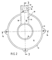
- the bell 12 has a conical jacket section 16 which extends around the entire circumference with the exception of a narrow suction box 18.
- the conical jacket section 16 ends at the rear in a cylindrical fastening flange 20 and extends at an acute angle of approximately 45 ° to the front up to approximately the diameter of the stirring screw 14 which it has in this axial region.
- At the front end of the conical jacket section 16 there is an inner pipe socket 22 pointing backwards, which extends as far as the front end face 24 of the submersible motor housing 10 and is cylindrical.
- the suction box 18 closes at the front end of the pipe socket 22 or the conical outer surface 16 with a front wall 28 which lies in a radial plane.
- the front wall is adjoined by two side walls 30, which are parallel to one another and reach rearwards as far as the fastening flange 20, which is reinforced at 32 in the area of the intake box 18.
- the conical outer surface 16 is recessed in the area of the suction box 18, as shown in dashed lines in FIG. 1 is illustrated.
- the side walls 30 pass through the conical outer surface 16 and extend down to the pipe socket 22, where an air outlet opening 34 is formed in the region of the suction box 18.
- An air inlet opening 42 is formed in the latter upper wall section 40 and it should be emphasized that the width and length of this upper wall section 40 is only slightly larger than the diameter of the air inlet opening 42. With the exception of the air inlet opening 42 and the air outlet opening 34, the suction box 18 is closed to the outside.
- the inner pipe socket 22 is cylindrical and at its front end the stirring screw 14 has a diameter such that only a very narrow running gap 44 remains, which is responsible for a good suction effect. With the exception of this narrow running gap 44, there are no further constrictions in the bell 12, the air can rather pass through the air inlet opening 42 into the suction box 18 through the suction hose, not shown, and there without significant expansion due to the narrow cross section of the suction box 18 to the air outlet opening 34 and through this into the area of the stirring screw 14 arrive.
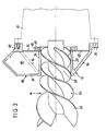
- FIG 3 shows a modification in that the housing end face 24 has an annular recess 25 which is filled by an annular sealing disk 46 made of acid-resistant rubber.
- the front end face of the sealing washer 46 lies flush with the front end face 24 of the housing 10.
- Another thinner annular sealing washer 48 made of the same material fits into a cylindrical extension which adjoins the conical jacket section 16 and is thus centered.
- This sealing washer 48 has a central circular recess equal to the inner diameter of the pipe socket 22.
- the wing arrangement 50 of the stirring screw 14 is different from that shown in FIG. 1 shown embodiment in a rear area 52 cylindrical on the outside and conical in the front area 54.
- the cylindrical region 52 extends over the entire length of the pipe socket 22 and forms there with the latter a narrow running gap with a constant gap width, which is decisive for a high suction effect and thus a correspondingly high air intake.
- the slope of the wing arrangement 50 in the rear area is constant and smaller than the slope in the front area 54,
Landscapes
- Chemical & Material Sciences (AREA)
- Chemical Kinetics & Catalysis (AREA)
- Life Sciences & Earth Sciences (AREA)
- Soil Sciences (AREA)
- Environmental Sciences (AREA)
- Mixers Of The Rotary Stirring Type (AREA)
- Aeration Devices For Treatment Of Activated Polluted Sludge (AREA)
Applications Claiming Priority (2)
| Application Number | Priority Date | Filing Date | Title |
|---|---|---|---|
| DE8811813U | 1988-09-17 | ||
| DE8811813U DE8811813U1 (de) | 1988-09-17 | 1988-09-17 | Gülle-Rührwerk |
Publications (2)
| Publication Number | Publication Date |
|---|---|
| EP0359933A2 true EP0359933A2 (fr) | 1990-03-28 |
| EP0359933A3 EP0359933A3 (fr) | 1990-05-16 |
Family
ID=6828054
Family Applications (1)
| Application Number | Title | Priority Date | Filing Date |
|---|---|---|---|
| EP89113188A Withdrawn EP0359933A3 (fr) | 1988-09-17 | 1989-07-19 | Agitateur de purin |
Country Status (2)
| Country | Link |
|---|---|
| EP (1) | EP0359933A3 (fr) |
| DE (1) | DE8811813U1 (fr) |
Families Citing this family (2)
| Publication number | Priority date | Publication date | Assignee | Title |
|---|---|---|---|---|
| DE3921464C2 (de) * | 1989-06-30 | 1994-02-24 | Helmut Dorn | Güllerührwerk |
| DE3925053A1 (de) * | 1989-07-28 | 1991-01-31 | Helmut Dorn | Ruehrgeraet und verfahren zu dessen betreiben |
Family Cites Families (3)
| Publication number | Priority date | Publication date | Assignee | Title |
|---|---|---|---|---|
| AT348953B (de) * | 1977-08-26 | 1979-03-12 | Alfa Laval Stalltech | Vorrichtung zur begasung und umwaelzung von fluessigkeiten |
| DE2933784C2 (de) * | 1979-08-21 | 1986-02-27 | Suma Sulzberger Maschinenbau Gmbh & Co Kg, Gerhard Thuerwaechter, 8961 Sulzberg | Jaucherührgerät |
| DE3621903A1 (de) * | 1986-06-30 | 1988-01-07 | Alois Maier | Ruehrwerk |
-
1988
- 1988-09-17 DE DE8811813U patent/DE8811813U1/de not_active Expired
-
1989
- 1989-07-19 EP EP89113188A patent/EP0359933A3/fr not_active Withdrawn
Also Published As
| Publication number | Publication date |
|---|---|
| DE8811813U1 (de) | 1988-10-27 |
| EP0359933A3 (fr) | 1990-05-16 |
Similar Documents
| Publication | Publication Date | Title |
|---|---|---|
| DE1528763C3 (de) | Kreiselpumpe | |
| EP0691877B1 (fr) | Filtre de retour pour liquides | |
| DE2551614C2 (de) | Axial kurzer Axialventilator | |
| DE2611885C3 (de) | Gerät zur Reinigung von Faserstoffsuspensionen | |
| DE69922198T2 (de) | Zentrifugalpumpe | |
| DE3026492A1 (de) | Vorrichtung zum mischen und entgasen von komponenten von kunstharzen, insbesondere von duroplastischen kunstharzen | |
| DE2166624A1 (de) | Vorrichtung zum zerkleinern von in einer fluessigkeit mitgeschwemmten feststoffen | |
| DE1801426A1 (de) | Zentrifugalanreicherer bzw.Zentrifugalabscheider | |
| DE3409463C2 (de) | Strömungspumpe, insbesondere Kreiselpumpe | |
| WO1995014440A1 (fr) | Separateur de liquide | |
| EP0775017B1 (fr) | Agitateur | |
| DE3340295A1 (de) | Pumpe zum foerdern von mit stueckigen verunreinigungen durchsetzten fluessigkeiten | |
| DE3238647A1 (de) | Mischer | |
| EP0465840B1 (fr) | Dispositif de filtration, notamment pour la séparation de grosses particules d'une suspension de lubrifiant et leur utilisation | |
| DE3404233A1 (de) | Zerkleinerungs- und ruehrvorrichtung fuer lebensmittel | |
| CH716848A2 (de) | Becken mit Bodenablauf. | |
| DE3921464C2 (de) | Güllerührwerk | |
| EP0524455A1 (fr) | Centrifugeuse | |
| DE19503266C2 (de) | Zerkleinerungsvorrichtung zum Einbau in Rohrleitungen | |
| DE2024215A1 (de) | Schaumpumpe | |
| DE9115728U1 (de) | Meßeinheit für Durchflußzähler für Flüssigkeiten | |
| DE2442446A1 (de) | Pumpe zum foerdern von wasser und abwasser | |
| DE8811813U1 (de) | Gülle-Rührwerk | |
| DE10052209B4 (de) | Staubsaugerfilter | |
| DE3622168C2 (fr) |
Legal Events
| Date | Code | Title | Description |
|---|---|---|---|
| PUAI | Public reference made under article 153(3) epc to a published international application that has entered the european phase |
Free format text: ORIGINAL CODE: 0009012 |
|
| AK | Designated contracting states |
Kind code of ref document: A2 Designated state(s): AT BE CH DE ES FR GB GR IT LI LU NL SE |
|
| PUAL | Search report despatched |
Free format text: ORIGINAL CODE: 0009013 |
|
| AK | Designated contracting states |
Kind code of ref document: A3 Designated state(s): AT BE CH DE ES FR GB GR IT LI LU NL SE |
|
| RHK1 | Main classification (correction) |
Ipc: A01C 3/02 |
|
| STAA | Information on the status of an ep patent application or granted ep patent |
Free format text: STATUS: THE APPLICATION IS DEEMED TO BE WITHDRAWN |
|
| 18D | Application deemed to be withdrawn |
Effective date: 19901117 |