EP0359945A2 - Dispositif d'air comprimé et de ventilation - Google Patents
Dispositif d'air comprimé et de ventilation Download PDFInfo
- Publication number
- EP0359945A2 EP0359945A2 EP89113750A EP89113750A EP0359945A2 EP 0359945 A2 EP0359945 A2 EP 0359945A2 EP 89113750 A EP89113750 A EP 89113750A EP 89113750 A EP89113750 A EP 89113750A EP 0359945 A2 EP0359945 A2 EP 0359945A2
- Authority
- EP
- European Patent Office
- Prior art keywords
- compressed air
- wall
- noise
- housing
- ventilation device
- Prior art date
- Legal status (The legal status is an assumption and is not a legal conclusion. Google has not performed a legal analysis and makes no representation as to the accuracy of the status listed.)
- Granted
Links
- 238000009423 ventilation Methods 0.000 claims abstract description 50
- 238000013016 damping Methods 0.000 claims abstract description 41
- 238000011144 upstream manufacturing Methods 0.000 claims abstract description 16
- 238000013022 venting Methods 0.000 claims description 12
- 239000011324 bead Substances 0.000 claims description 11
- 239000013013 elastic material Substances 0.000 claims description 3
- 230000006378 damage Effects 0.000 abstract description 2
- 238000000034 method Methods 0.000 description 3
- 230000003584 silencer Effects 0.000 description 3
- 230000008021 deposition Effects 0.000 description 2
- 230000008014 freezing Effects 0.000 description 2
- 238000007710 freezing Methods 0.000 description 2
- OKTJSMMVPCPJKN-UHFFFAOYSA-N Carbon Chemical compound [C] OKTJSMMVPCPJKN-UHFFFAOYSA-N 0.000 description 1
- 230000002411 adverse Effects 0.000 description 1
- 230000009172 bursting Effects 0.000 description 1
- 229910052799 carbon Inorganic materials 0.000 description 1
- 239000003795 chemical substances by application Substances 0.000 description 1
- 239000003245 coal Substances 0.000 description 1
- 230000007423 decrease Effects 0.000 description 1
- 230000006735 deficit Effects 0.000 description 1
- 238000011161 development Methods 0.000 description 1
- 230000018109 developmental process Effects 0.000 description 1
- 230000000149 penetrating effect Effects 0.000 description 1
- 230000035699 permeability Effects 0.000 description 1
- 230000000284 resting effect Effects 0.000 description 1
- 230000007704 transition Effects 0.000 description 1
Images


Classifications
-
- B—PERFORMING OPERATIONS; TRANSPORTING
- B60—VEHICLES IN GENERAL
- B60T—VEHICLE BRAKE CONTROL SYSTEMS OR PARTS THEREOF; BRAKE CONTROL SYSTEMS OR PARTS THEREOF, IN GENERAL; ARRANGEMENT OF BRAKING ELEMENTS ON VEHICLES IN GENERAL; PORTABLE DEVICES FOR PREVENTING UNWANTED MOVEMENT OF VEHICLES; VEHICLE MODIFICATIONS TO FACILITATE COOLING OF BRAKES
- B60T17/00—Component parts, details, or accessories of power brake systems not covered by groups B60T8/00, B60T13/00 or B60T15/00, or presenting other characteristic features
- B60T17/002—Air treatment devices
- B60T17/008—Silencer devices
-
- F—MECHANICAL ENGINEERING; LIGHTING; HEATING; WEAPONS; BLASTING
- F16—ENGINEERING ELEMENTS AND UNITS; GENERAL MEASURES FOR PRODUCING AND MAINTAINING EFFECTIVE FUNCTIONING OF MACHINES OR INSTALLATIONS; THERMAL INSULATION IN GENERAL
- F16L—PIPES; JOINTS OR FITTINGS FOR PIPES; SUPPORTS FOR PIPES, CABLES OR PROTECTIVE TUBING; MEANS FOR THERMAL INSULATION IN GENERAL
- F16L55/00—Devices or appurtenances for use in, or in connection with, pipes or pipe systems
- F16L55/02—Energy absorbers; Noise absorbers
- F16L55/027—Throttle passages
- F16L55/02745—Throttle passages by passing through a mass of particles or a porous member
-
- F—MECHANICAL ENGINEERING; LIGHTING; HEATING; WEAPONS; BLASTING
- F16—ENGINEERING ELEMENTS AND UNITS; GENERAL MEASURES FOR PRODUCING AND MAINTAINING EFFECTIVE FUNCTIONING OF MACHINES OR INSTALLATIONS; THERMAL INSULATION IN GENERAL
- F16L—PIPES; JOINTS OR FITTINGS FOR PIPES; SUPPORTS FOR PIPES, CABLES OR PROTECTIVE TUBING; MEANS FOR THERMAL INSULATION IN GENERAL
- F16L55/00—Devices or appurtenances for use in, or in connection with, pipes or pipe systems
- F16L55/02—Energy absorbers; Noise absorbers
- F16L55/033—Noise absorbers
-
- F—MECHANICAL ENGINEERING; LIGHTING; HEATING; WEAPONS; BLASTING
- F16—ENGINEERING ELEMENTS AND UNITS; GENERAL MEASURES FOR PRODUCING AND MAINTAINING EFFECTIVE FUNCTIONING OF MACHINES OR INSTALLATIONS; THERMAL INSULATION IN GENERAL
- F16L—PIPES; JOINTS OR FITTINGS FOR PIPES; SUPPORTS FOR PIPES, CABLES OR PROTECTIVE TUBING; MEANS FOR THERMAL INSULATION IN GENERAL
- F16L55/00—Devices or appurtenances for use in, or in connection with, pipes or pipe systems
- F16L55/02—Energy absorbers; Noise absorbers
- F16L55/033—Noise absorbers
- F16L55/0336—Noise absorbers by means of sound-absorbing materials
Definitions
- the invention relates to a compressed air ventilation device according to the preamble of patent claim 1.
- Such a compressed air venting device is known from EP 0 019 855.
- the invention is therefore based on the object of designing a compressed air venting device of the type mentioned at the outset in such a way that excessive build-up of pressure is prevented.
- the invention has the particular advantage that the arrangement of a pressure relief valve designed as a pressure relief valve between the ventilation space upstream of the noise-damping means and the expansion space downstream of the noise-damping means of the compressed air venting device, when a predetermined maximum dynamic pressure value in the ventilation space is exceeded, the dynamic pressure is reduced via the pressure relief valve.
- a significant impairment of the function of the devices upstream of the compressed air ventilation device or even destruction of these devices is avoided.
- An overpressure safety device acting in the manner of an overflow valve can also be provided in the housing wall of the compressed air venting device, so that the dynamic pressure is released directly to the atmosphere.
- a bypass channel can be provided between the ventilation space upstream of the noise damping means and the relaxation space downstream of the noise damping means, via which these two spaces are constantly connected to each other.
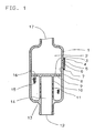
- FIG. 1 shows a muffler serving as a compressed air venting device, which has a housing (1) with an inlet opening (17) and an outlet opening (12) for compressed air.
- the muffler with its inlet opening is e.g. connected to the outlet of a pressure control valve which is arranged between a compressor and a compressed air reservoir.
- Noise-damping means are provided in the housing (1) of the noise damper, which subdivide the interior of the housing (1) into a ventilation space upstream of the noise-damping means and a relaxation space downstream of the noise-damping means.
- the noise-damping means consist of an annular wire mesh body (15) which surrounds a tube (10) running in the direction of the longitudinal axis of the housing (1).
- the wall of the tube (10) is provided with a plurality of passages (11) in the area surrounded by the wire mesh body (15).
- the tube is attached at one end to a plate (3) in a pressure-tight manner, which plate is attached to the inside wall of the housing in the ventilation space upstream of the noise-damping means and extends transversely to the longitudinal axis of the housing (1).
- the plate (3) has passages (9, 16) outside the area surrounded by the tube (10), via which the ventilation space serving as the inlet chamber (2) and connected upstream of the noise-damping means is continuously connected to the noise-damping means.
- the tube (10) opens with its end facing away from the plate (3), surrounding the outlet opening (12) on a base part (13) of the housing (1).
- the space delimited by the tube (10) is the relaxation space downstream of the noise-damping means and, in this exemplary embodiment, serves as an outlet chamber (14) for the compressed air.
- passage opening (8) which is closed by a plug inserted into it and serving as a closure member (6).
- the passage opening (8) and the closure member (6) are preferably designed to taper conically in the direction of the inlet chamber (2).
- the plate (6) can be designed as a type plate for the noise damper. It can be formed in one piece with the closure member (6).
- the plate (6) is held by two frame-like parts (4) and (7) which are molded onto the outer surface of the housing (1).
- the closure member (6) and the passage opening (8) have the function of a pressure relief valve, via which the ventilation space can be connected to the atmosphere.
- the compressed air When the excess compressed air is blown off from the pressure control valve upstream of the silencer, the compressed air enters the inlet chamber (2) of the silencer.
- the compressed air flows from the inlet chamber (2) through the passages (9, 16) provided in the plate (3) into the space containing the wire mesh body (15) and passes through the wire mesh and the passages provided in the tube (10) into the outlet chamber (14).
- the compressed air flows from the outlet chamber (14) through the outlet opening (12) to the atmosphere.
- the wire mesh body (14) becomes clogged, for example due to the deposition of coal or icy condensate, a back pressure builds up in the inlet chamber (2).
- the closure member (6) is affected by the dynamic pressure in the ventilation space (inlet chamber 2). pressed out of the passage opening (8) provided in the housing wall.
- the elastic plate (5) deforms to such an extent that it is also pressed out of its frame-like holding parts (4 and 7).
- the elastic plate (5) can be attached on one side to the wall of the housing.
- the noise damper shown in Figure 2 has essentially the same structure as the noise damper shown in Figure 1.
- the components that are the same as the components shown in FIG. 1 are provided with the same reference numbers.
- Fig.2 shows a muffler, which has a housing (1) with an inlet opening (17) and an outlet opening (12) for compressed air.
- Noise-damping means are provided in the housing (1) of the noise damper, which subdivide the interior of the housing (1) into a ventilation space upstream of the noise-damping means and a relaxation space downstream of the noise-damping means.
- the noise-damping means consist of an annular wire mesh body (15) which surrounds a tube (10) running in the direction of the longitudinal axis of the housing (1).
- the wall of the tube (10) is that of the wire mesh body (15) surrounding area with a plurality of passages (11).
- One end of the tube (10) is fastened in a pressure-tight manner to a plate (3), which is attached to the inside wall of the housing in the ventilation space upstream of the noise-damping means and extends transversely to the longitudinal axis of the housing (1).
- the plate (3) divides the ventilation space upstream of the noise-damping means into an inlet chamber (2) connected to the inlet opening (17) and an expansion chamber (19).
- the inlet chamber (2) is continuously connected to the expansion chamber (19) via passages (9, 16) provided in the plate (3).
- the tube (10) opens with its end facing away from the plate (3) surrounding the outlet opening (12) provided in the base part (13) of the housing (1), on the base part (13).
- the space delimited by the inner wall of the tube (10) is the relaxation space downstream of the noise-damping means and, in this exemplary embodiment, serves as an outlet chamber (14) for the compressed air.
- passage opening (8) which is closed by a plug inserted into it and serving as a closure member (6).
- the passage opening (8) and the closure member (6) are preferably designed to taper conically in the direction of the inlet chamber (2).
- the plate (5) is held by two frame-like parts (4 and 7) which are molded onto the outer surface of the housing (1).
- an opening (20) designed as a bypass channel is arranged near the plate (3).
- the opening (20) preferably has a throttle point.
- the expansion chamber (19) is continuously connected to the outlet chamber (14) via the opening (20).
- the compressed air flowing into the inlet chamber (2) passes through the passages (9, 16) provided in the plate (3) into the expansion chamber (19).
- the compressed air expands as much as possible and on the one hand passes directly through the wire mesh body (15) and the passages (11) provided in the tube (10) into the outlet chamber (14) and on the other hand through the bypass channel (20) the expansion joint (19) into the outlet chamber (14).
- the compressed air is discharged from the outlet chamber (14) through the outlet opening (12) to the atmosphere.
- the silencer remains functional, since the dynamic pressure that slowly builds up in the expansion chamber (19) is released to the atmosphere via the bypass channel (20) and the outlet chamber (14).
- the closure member (6) pressed out of the back pressure from the passage opening (8) in the wall of the housing (1) and deforms the elastic plate (5) in the direction away from the outer surface of the housing (1). During this process, the plate (6) is pressed out of its frame-like holding parts (4, 7).
- the overpressure protection device (8, 5, 6, 4, 7) provided in the wall of the housing (1) also works when the plate (3) is designed as a perforated plate and the openings of the perforated plate clog, so that in the Inlet chamber (2) creates a back pressure that is too high.
- the noise damper shown in Figure 3 has essentially the same structure as the noise damper shown in Figure 2. Instead of a bypass channel, an opening (24) is provided in the wall of the tube (10), which is closed by an elastic tab (25.
- the opening (24) and the tab (25) form a pressure relief valve Wall of the housing (1) provided overpressure protection device is designed according to the embodiment of Figure 3 as a predetermined breaking point.
- the predetermined breaking point consists of a preferably circular wall part (23) which is preferably thinner than the rest of the wall of the housing (1).
- the thinner wall part (23) is held by a bead (21), the one end (21) of the bead with the wall of the housing (1) and the other end (22) of the Bead, which is thinner than the wall (1) and thus forms the actual predetermined breaking point, is connected to the thinner wall part (23).
- the wall part (23) held by the bead can also have the same thickness as the housing wall (1). In such a case, however, the transition area between the bead (21) and the wall part (23) must be made thinner than the wall of the housing (1) in order to obtain a precisely defined fracture profile.
- a simple non-return valve which consists of an opening and a non-return valve, can of course also be used as the excess pressure safety device or as the excess pressure valve.
- a check valve can be arranged in the wall of the housing (1) or in the wall of the tube (10).
- a stopper (6) a ball closing the passage opening (8) can be provided.
- the pressure relief valve on or in a component which separates the ventilation space upstream of the noise-damping means from the relaxation space downstream of the noise-damping means.
- the pressure relief valve can be provided in the plate (3) instead of in the wall of the housing (1).
- the pressure relief valve must be arranged in the area of the plate (3) which is delimited by the free interior of the tube (10).
- each space such as the expansion chamber, the inlet chamber, is the To look at the inlet port. That is, each room, which is upstream of the noise-damping means, has the function of a ventilation room, regardless of whether it is located in a housing, as shown in the exemplary embodiments of the invention, or in a part of a device, in or on which noise damping means are arranged.
- the bypass channel can be designed as a channel penetrating the noise-damping means.
- Such a channel can contain a pressure relief valve (wall closing the channel passage cross section with predetermined breaking point or check valve).
- the pressure relief device referred to above as the pressure relief valve, need not of course include the typical features of a valve, such as the valve seat and valve body. As already described, it can be designed as a predetermined breaking point in a wall (also in the wall of a pipe) or as a bursting tab.
- the rupture flap is a flap which closes the opening in a wall and is a component of this wall and, in the event of overpressure in a space adjacent to this wall, is pushed more or less out of the opening. After the overpressure has dropped, the tab returns to its original position.
- the pressure relief valve can be arranged in each partial area of a wall delimiting the ventilation space (the partial area delimiting the inlet chamber or the expansion chamber of the wall of the housing 1 or a wall part of a device or also a wall part delimiting the connecting piece).
Landscapes
- Engineering & Computer Science (AREA)
- General Engineering & Computer Science (AREA)
- Mechanical Engineering (AREA)
- Transportation (AREA)
- Safety Valves (AREA)
- Compressors, Vaccum Pumps And Other Relevant Systems (AREA)
- Pipe Accessories (AREA)
- Structures Of Non-Positive Displacement Pumps (AREA)
Applications Claiming Priority (2)
| Application Number | Priority Date | Filing Date | Title |
|---|---|---|---|
| DE3832029 | 1988-09-21 | ||
| DE3832029A DE3832029C2 (de) | 1988-09-21 | 1988-09-21 | Druckluft-Entlüftungseinrichtung |
Related Child Applications (2)
| Application Number | Title | Priority Date | Filing Date |
|---|---|---|---|
| EP19930109340 Division EP0565136A3 (fr) | 1988-09-21 | 1989-07-26 | Dispositif d'air comprimé et de ventilation |
| EP93109340.5 Division-Into | 1993-06-11 |
Publications (3)
| Publication Number | Publication Date |
|---|---|
| EP0359945A2 true EP0359945A2 (fr) | 1990-03-28 |
| EP0359945A3 EP0359945A3 (fr) | 1992-02-12 |
| EP0359945B1 EP0359945B1 (fr) | 1994-08-31 |
Family
ID=6363389
Family Applications (2)
| Application Number | Title | Priority Date | Filing Date |
|---|---|---|---|
| EP89113750A Expired - Lifetime EP0359945B1 (fr) | 1988-09-21 | 1989-07-26 | Dispositif d'air comprimé et de ventilation |
| EP19930109340 Ceased EP0565136A3 (fr) | 1988-09-21 | 1989-07-26 | Dispositif d'air comprimé et de ventilation |
Family Applications After (1)
| Application Number | Title | Priority Date | Filing Date |
|---|---|---|---|
| EP19930109340 Ceased EP0565136A3 (fr) | 1988-09-21 | 1989-07-26 | Dispositif d'air comprimé et de ventilation |
Country Status (2)
| Country | Link |
|---|---|
| EP (2) | EP0359945B1 (fr) |
| DE (2) | DE3832029C2 (fr) |
Cited By (2)
| Publication number | Priority date | Publication date | Assignee | Title |
|---|---|---|---|---|
| DE102017122215A1 (de) * | 2017-09-26 | 2019-03-28 | Knorr-Bremse Systeme für Nutzfahrzeuge GmbH | Geräuschdämpfer für Druckluftsysteme und ein Verfahren zu dessen Herstellung |
| CN110864180A (zh) * | 2019-11-07 | 2020-03-06 | 哈尔滨工程大学 | 一种高效紧凑型海水管路消声器 |
Families Citing this family (8)
| Publication number | Priority date | Publication date | Assignee | Title |
|---|---|---|---|---|
| DE4205458A1 (de) * | 1992-02-22 | 1993-08-26 | Bosch Gmbh Robert | Schalldaempfer fuer geblaese |
| DE4412517C2 (de) * | 1994-04-12 | 1997-01-16 | Bbm Technik Ges Fuer Die Verwe | Ausblaseschalldämpfer |
| FR2834312B1 (fr) * | 2001-12-27 | 2006-11-24 | Acoustique Ind Sarl Soc D | Diffuseur silencieux pour la detente de gaz |
| DE102008029489A1 (de) * | 2008-06-20 | 2009-12-24 | Wabco Gmbh | Geräuschdämpfer für Druckluftsysteme von Fahrzeugen |
| DE102016100139A1 (de) | 2016-01-05 | 2017-07-06 | Knorr-Bremse Systeme für Nutzfahrzeuge GmbH | Geräuschdämpfer für ein Druckluftsystem eines Fahrzeugs, insbesondere Nutzfahrzeugs |
| DE102016100140A1 (de) | 2016-01-05 | 2017-07-06 | Knorr-Bremse Systeme für Nutzfahrzeuge GmbH | Geräuschdämpfer für ein Druckluftsystem eines Fahrzeugs, insbesondere eines Nutzfahrzeugs |
| CN112212116A (zh) * | 2020-10-16 | 2021-01-12 | 张贵杰 | 一种利用气囊结构实现消音的软风管对接安装装置 |
| CN112503287B (zh) * | 2020-11-27 | 2023-06-27 | 江苏盐阜电站阀门辅机制造有限公司 | 一种用于减温减压阀的消声器 |
Family Cites Families (7)
| Publication number | Priority date | Publication date | Assignee | Title |
|---|---|---|---|---|
| US2766840A (en) * | 1951-04-21 | 1956-10-16 | Webster Electric Co Inc | Vibration absorber |
| US3470979A (en) * | 1967-10-10 | 1969-10-07 | Wilhelm S Everett | Fluid pulsation dampener with thimble |
| FR2232976A5 (en) * | 1973-06-08 | 1975-01-03 | Bertin & Cie | Exhaust gas pipe sound damping - by incasing apertured pipe to define tortous gas path through coaxial cylinder walls |
| US3920095A (en) * | 1974-02-01 | 1975-11-18 | Brunswick Corp | Free flow sound attenuating device and method of using |
| DE2910209A1 (de) * | 1979-03-15 | 1980-09-25 | Wabco Fahrzeugbremsen Gmbh | Geraeuschdaempfer fuer ventileinrichtungen in druckluft-bremsanlagen |
| DE2922677C2 (de) * | 1979-06-02 | 1982-12-09 | Wabco Fahrzeugbremsen Gmbh, 3000 Hannover | Geräuschdämpfer für Ventileinrichtungen in Druckluftbremsanlagen |
| DE3343587A1 (de) * | 1983-12-02 | 1984-07-12 | Daimler-Benz Ag, 7000 Stuttgart | Schalldaempfer fuer stroemende gase |
-
1988
- 1988-09-21 DE DE3832029A patent/DE3832029C2/de not_active Expired - Lifetime
-
1989
- 1989-07-26 DE DE58908264T patent/DE58908264D1/de not_active Expired - Fee Related
- 1989-07-26 EP EP89113750A patent/EP0359945B1/fr not_active Expired - Lifetime
- 1989-07-26 EP EP19930109340 patent/EP0565136A3/fr not_active Ceased
Cited By (3)
| Publication number | Priority date | Publication date | Assignee | Title |
|---|---|---|---|---|
| DE102017122215A1 (de) * | 2017-09-26 | 2019-03-28 | Knorr-Bremse Systeme für Nutzfahrzeuge GmbH | Geräuschdämpfer für Druckluftsysteme und ein Verfahren zu dessen Herstellung |
| US11505171B2 (en) | 2017-09-26 | 2022-11-22 | Knorr-Bremse Systeme Fuer Nutzfahrzeuge Gmbh | Noise damper for compressed air systems and a method for the production of same |
| CN110864180A (zh) * | 2019-11-07 | 2020-03-06 | 哈尔滨工程大学 | 一种高效紧凑型海水管路消声器 |
Also Published As
| Publication number | Publication date |
|---|---|
| EP0359945A3 (fr) | 1992-02-12 |
| DE58908264D1 (de) | 1994-10-06 |
| EP0359945B1 (fr) | 1994-08-31 |
| EP0565136A3 (fr) | 1993-10-20 |
| DE3832029C2 (de) | 1997-12-11 |
| EP0565136A2 (fr) | 1993-10-13 |
| DE3832029A1 (de) | 1990-03-22 |
Similar Documents
| Publication | Publication Date | Title |
|---|---|---|
| DE4409252C2 (de) | Luftfederungsanlage | |
| EP1165333B2 (fr) | Systeme d'amortisseur pneumatique pour un vehicule automobile | |
| DE102007011256B4 (de) | Druckluftversorgungseinrichtung mit verbesserter Regenerationsfähigkeit | |
| EP0304610A2 (fr) | Dispositif de soupape à réglage | |
| EP0884203A1 (fr) | Dispositif de réglage du niveau pour véhicules à ressorts à gaz | |
| EP1046521A2 (fr) | Dispositif de réglage du niveau pour véhicules à ressorts pneumatiques | |
| EP0308618A2 (fr) | Soupape de retenue, notamment pour air comprimé | |
| EP0359945B1 (fr) | Dispositif d'air comprimé et de ventilation | |
| EP0596220B1 (fr) | Dispositif d'air comprimé et de ventilation | |
| EP0155346A2 (fr) | Dispositif de réglage de la pression de pneumatiques | |
| EP1040947A2 (fr) | Dispositif de climatisation d'un véhicule | |
| EP1134467A1 (fr) | Installation de soupape dans un système de refrigération | |
| DE102008053994A1 (de) | Druckluftbegrenzungseinrichtung | |
| EP0659621A1 (fr) | Dispositif de limitation de pression | |
| DE2910209A1 (de) | Geraeuschdaempfer fuer ventileinrichtungen in druckluft-bremsanlagen | |
| EP0537483B1 (fr) | Sécheur d'air pour installation d'air comprimé chargeable par un compresseur, en particulier pour installation de freins à air comprimé de véhicules | |
| DE102021117390A1 (de) | Arbeitsmediumtank für einen hydrodynamischen Retarder | |
| DE102016115360A1 (de) | Überströmventil zum zumindest teilweisen Verschließen und Öffnen eines Fluidleitungssystems | |
| EP0289712A2 (fr) | Régulateur de pression | |
| EP0097223B1 (fr) | Dispositif pour l'amortissement de l'air forcé d'installations de valves | |
| DE3908807A1 (de) | Einrichtung zur aenderung des druckes im reifen eines fahrzeuges | |
| DE3240710A1 (de) | Entlueftungsschalldaempfer | |
| EP0093842A1 (fr) | Silencieux pour dispositifs de soupape dans des installations de frein à air comprimé | |
| EP0359948A2 (fr) | Silencieux | |
| EP0845601B1 (fr) | Vanne de démarrage |
Legal Events
| Date | Code | Title | Description |
|---|---|---|---|
| PUAI | Public reference made under article 153(3) epc to a published international application that has entered the european phase |
Free format text: ORIGINAL CODE: 0009012 |
|
| AK | Designated contracting states |
Kind code of ref document: A2 Designated state(s): DE FR GB IT NL SE |
|
| PUAL | Search report despatched |
Free format text: ORIGINAL CODE: 0009013 |
|
| AK | Designated contracting states |
Kind code of ref document: A3 Designated state(s): DE FR GB IT NL SE |
|
| 17P | Request for examination filed |
Effective date: 19920117 |
|
| 17Q | First examination report despatched |
Effective date: 19921117 |
|
| RAP1 | Party data changed (applicant data changed or rights of an application transferred) |
Owner name: WABCO VERMOEGENSVERWALTUNGS-GMBH |
|
| GRAA | (expected) grant |
Free format text: ORIGINAL CODE: 0009210 |
|
| AK | Designated contracting states |
Kind code of ref document: B1 Designated state(s): DE FR GB IT NL SE |
|
| XX | Miscellaneous (additional remarks) |
Free format text: TEILANMELDUNG 93109340.5 EINGEREICHT AM 26/07/89. |
|
| ITF | It: translation for a ep patent filed | ||
| REF | Corresponds to: |
Ref document number: 58908264 Country of ref document: DE Date of ref document: 19941006 |
|
| ET | Fr: translation filed | ||
| GBT | Gb: translation of ep patent filed (gb section 77(6)(a)/1977) |
Effective date: 19941214 |
|
| EAL | Se: european patent in force in sweden |
Ref document number: 89113750.7 |
|
| PLBE | No opposition filed within time limit |
Free format text: ORIGINAL CODE: 0009261 |
|
| STAA | Information on the status of an ep patent application or granted ep patent |
Free format text: STATUS: NO OPPOSITION FILED WITHIN TIME LIMIT |
|
| RAP2 | Party data changed (patent owner data changed or rights of a patent transferred) |
Owner name: WABCO GMBH |
|
| 26N | No opposition filed | ||
| NLT2 | Nl: modifications (of names), taken from the european patent patent bulletin |
Owner name: WABCO GMBH |
|
| PGFP | Annual fee paid to national office [announced via postgrant information from national office to epo] |
Ref country code: GB Payment date: 19980717 Year of fee payment: 10 |
|
| PGFP | Annual fee paid to national office [announced via postgrant information from national office to epo] |
Ref country code: NL Payment date: 19980731 Year of fee payment: 10 Ref country code: FR Payment date: 19980731 Year of fee payment: 10 |
|
| PG25 | Lapsed in a contracting state [announced via postgrant information from national office to epo] |
Ref country code: GB Free format text: LAPSE BECAUSE OF NON-PAYMENT OF DUE FEES Effective date: 19990726 |
|
| PG25 | Lapsed in a contracting state [announced via postgrant information from national office to epo] |
Ref country code: FR Free format text: THE PATENT HAS BEEN ANNULLED BY A DECISION OF A NATIONAL AUTHORITY Effective date: 19990731 |
|
| PG25 | Lapsed in a contracting state [announced via postgrant information from national office to epo] |
Ref country code: NL Free format text: LAPSE BECAUSE OF NON-PAYMENT OF DUE FEES Effective date: 20000201 |
|
| GBPC | Gb: european patent ceased through non-payment of renewal fee |
Effective date: 19990726 |
|
| NLV4 | Nl: lapsed or anulled due to non-payment of the annual fee |
Effective date: 20000201 |
|
| REG | Reference to a national code |
Ref country code: FR Ref legal event code: ST |
|
| PGFP | Annual fee paid to national office [announced via postgrant information from national office to epo] |
Ref country code: DE Payment date: 20060731 Year of fee payment: 18 Ref country code: IT Payment date: 20060731 Year of fee payment: 18 |
|
| EUG | Se: european patent has lapsed | ||
| PG25 | Lapsed in a contracting state [announced via postgrant information from national office to epo] |
Ref country code: DE Free format text: LAPSE BECAUSE OF NON-PAYMENT OF DUE FEES Effective date: 20080201 Ref country code: SE Free format text: LAPSE BECAUSE OF NON-PAYMENT OF DUE FEES Effective date: 20070727 |
|
| PGFP | Annual fee paid to national office [announced via postgrant information from national office to epo] |
Ref country code: SE Payment date: 20060706 Year of fee payment: 18 |
|
| PG25 | Lapsed in a contracting state [announced via postgrant information from national office to epo] |
Ref country code: IT Free format text: LAPSE BECAUSE OF NON-PAYMENT OF DUE FEES Effective date: 20070726 |