EP0359977A2 - Four de traitement thermique pour une installation de coulée ébauche - Google Patents
Four de traitement thermique pour une installation de coulée ébauche Download PDFInfo
- Publication number
- EP0359977A2 EP0359977A2 EP89114784A EP89114784A EP0359977A2 EP 0359977 A2 EP0359977 A2 EP 0359977A2 EP 89114784 A EP89114784 A EP 89114784A EP 89114784 A EP89114784 A EP 89114784A EP 0359977 A2 EP0359977 A2 EP 0359977A2
- Authority
- EP
- European Patent Office
- Prior art keywords
- heating furnace
- hearth
- strip
- storage chamber
- furnace according
- Prior art date
- Legal status (The legal status is an assumption and is not a legal conclusion. Google has not performed a legal analysis and makes no representation as to the accuracy of the status listed.)
- Withdrawn
Links
Images

Classifications
-
- F—MECHANICAL ENGINEERING; LIGHTING; HEATING; WEAPONS; BLASTING
- F27—FURNACES; KILNS; OVENS; RETORTS
- F27B—FURNACES, KILNS, OVENS OR RETORTS IN GENERAL; OPEN SINTERING OR LIKE APPARATUS
- F27B9/00—Furnaces through which the charge is moved mechanically, e.g. of tunnel type; Similar furnaces in which the charge moves by gravity
- F27B9/14—Furnaces through which the charge is moved mechanically, e.g. of tunnel type; Similar furnaces in which the charge moves by gravity characterised by the path of the charge during treatment; characterised by the means by which the charge is moved during treatment
- F27B9/20—Furnaces through which the charge is moved mechanically, e.g. of tunnel type; Similar furnaces in which the charge moves by gravity characterised by the path of the charge during treatment; characterised by the means by which the charge is moved during treatment the charge moving in a substantially straight path
- F27B9/22—Furnaces through which the charge is moved mechanically, e.g. of tunnel type; Similar furnaces in which the charge moves by gravity characterised by the path of the charge during treatment; characterised by the means by which the charge is moved during treatment the charge moving in a substantially straight path on rails, e.g. under the action of scrapers or pushers
-
- F—MECHANICAL ENGINEERING; LIGHTING; HEATING; WEAPONS; BLASTING
- F27—FURNACES; KILNS; OVENS; RETORTS
- F27B—FURNACES, KILNS, OVENS OR RETORTS IN GENERAL; OPEN SINTERING OR LIKE APPARATUS
- F27B9/00—Furnaces through which the charge is moved mechanically, e.g. of tunnel type; Similar furnaces in which the charge moves by gravity
- F27B9/30—Details, accessories or equipment specially adapted for furnaces of these types
- F27B9/38—Arrangements of devices for charging
-
- B—PERFORMING OPERATIONS; TRANSPORTING
- B21—MECHANICAL METAL-WORKING WITHOUT ESSENTIALLY REMOVING MATERIAL; PUNCHING METAL
- B21B—ROLLING OF METAL
- B21B1/00—Metal-rolling methods or mills for making semi-finished products of solid or profiled cross-section; Sequence of operations in milling trains; Layout of rolling-mill plant, e.g. grouping of stands; Succession of passes or of sectional pass alternations
- B21B1/46—Metal-rolling methods or mills for making semi-finished products of solid or profiled cross-section; Sequence of operations in milling trains; Layout of rolling-mill plant, e.g. grouping of stands; Succession of passes or of sectional pass alternations for rolling metal immediately subsequent to continuous casting
- B21B1/466—Metal-rolling methods or mills for making semi-finished products of solid or profiled cross-section; Sequence of operations in milling trains; Layout of rolling-mill plant, e.g. grouping of stands; Succession of passes or of sectional pass alternations for rolling metal immediately subsequent to continuous casting in a non-continuous process, i.e. the cast being cut before rolling
-
- B—PERFORMING OPERATIONS; TRANSPORTING
- B21—MECHANICAL METAL-WORKING WITHOUT ESSENTIALLY REMOVING MATERIAL; PUNCHING METAL
- B21B—ROLLING OF METAL
- B21B45/00—Devices for surface or other treatment of work, specially combined with or arranged in, or specially adapted for use in connection with, metal-rolling mills
- B21B45/004—Heating the product
-
- F—MECHANICAL ENGINEERING; LIGHTING; HEATING; WEAPONS; BLASTING
- F27—FURNACES; KILNS; OVENS; RETORTS
- F27B—FURNACES, KILNS, OVENS OR RETORTS IN GENERAL; OPEN SINTERING OR LIKE APPARATUS
- F27B9/00—Furnaces through which the charge is moved mechanically, e.g. of tunnel type; Similar furnaces in which the charge moves by gravity
- F27B9/30—Details, accessories or equipment specially adapted for furnaces of these types
- F27B2009/3094—Means to store a part of the charge in the furnace
-
- F—MECHANICAL ENGINEERING; LIGHTING; HEATING; WEAPONS; BLASTING
- F27—FURNACES; KILNS; OVENS; RETORTS
- F27B—FURNACES, KILNS, OVENS OR RETORTS IN GENERAL; OPEN SINTERING OR LIKE APPARATUS
- F27B9/00—Furnaces through which the charge is moved mechanically, e.g. of tunnel type; Similar furnaces in which the charge moves by gravity
- F27B9/30—Details, accessories or equipment specially adapted for furnaces of these types
- F27B9/38—Arrangements of devices for charging
- F27B2009/386—Lateral intake or outtake
-
- F—MECHANICAL ENGINEERING; LIGHTING; HEATING; WEAPONS; BLASTING
- F27—FURNACES; KILNS; OVENS; RETORTS
- F27B—FURNACES, KILNS, OVENS OR RETORTS IN GENERAL; OPEN SINTERING OR LIKE APPARATUS
- F27B9/00—Furnaces through which the charge is moved mechanically, e.g. of tunnel type; Similar furnaces in which the charge moves by gravity
- F27B9/30—Details, accessories or equipment specially adapted for furnaces of these types
- F27B9/38—Arrangements of devices for charging
- F27B2009/386—Lateral intake or outtake
- F27B2009/388—Centrally in the lateral wall
-
- F—MECHANICAL ENGINEERING; LIGHTING; HEATING; WEAPONS; BLASTING
- F27—FURNACES; KILNS; OVENS; RETORTS
- F27B—FURNACES, KILNS, OVENS OR RETORTS IN GENERAL; OPEN SINTERING OR LIKE APPARATUS
- F27B9/00—Furnaces through which the charge is moved mechanically, e.g. of tunnel type; Similar furnaces in which the charge moves by gravity
- F27B9/14—Furnaces through which the charge is moved mechanically, e.g. of tunnel type; Similar furnaces in which the charge moves by gravity characterised by the path of the charge during treatment; characterised by the means by which the charge is moved during treatment
- F27B9/20—Furnaces through which the charge is moved mechanically, e.g. of tunnel type; Similar furnaces in which the charge moves by gravity characterised by the path of the charge during treatment; characterised by the means by which the charge is moved during treatment the charge moving in a substantially straight path
- F27B9/24—Furnaces through which the charge is moved mechanically, e.g. of tunnel type; Similar furnaces in which the charge moves by gravity characterised by the path of the charge during treatment; characterised by the means by which the charge is moved during treatment the charge moving in a substantially straight path being carried by a conveyor
- F27B9/2407—Furnaces through which the charge is moved mechanically, e.g. of tunnel type; Similar furnaces in which the charge moves by gravity characterised by the path of the charge during treatment; characterised by the means by which the charge is moved during treatment the charge moving in a substantially straight path being carried by a conveyor the conveyor being constituted by rollers (roller hearth furnace)
-
- F—MECHANICAL ENGINEERING; LIGHTING; HEATING; WEAPONS; BLASTING
- F27—FURNACES; KILNS; OVENS; RETORTS
- F27D—DETAILS OR ACCESSORIES OF FURNACES, KILNS, OVENS OR RETORTS, IN SO FAR AS THEY ARE OF KINDS OCCURRING IN MORE THAN ONE KIND OF FURNACE
- F27D3/00—Charging; Discharging; Manipulation of charge
- F27D2003/0034—Means for moving, conveying, transporting the charge in the furnace or in the charging facilities
- F27D2003/0042—Means for moving, conveying, transporting the charge in the furnace or in the charging facilities comprising roller trains
- F27D2003/0044—Means for moving, conveying, transporting the charge in the furnace or in the charging facilities comprising roller trains at least one of them being removable
-
- F—MECHANICAL ENGINEERING; LIGHTING; HEATING; WEAPONS; BLASTING
- F27—FURNACES; KILNS; OVENS; RETORTS
- F27D—DETAILS OR ACCESSORIES OF FURNACES, KILNS, OVENS OR RETORTS, IN SO FAR AS THEY ARE OF KINDS OCCURRING IN MORE THAN ONE KIND OF FURNACE
- F27D3/00—Charging; Discharging; Manipulation of charge
- F27D2003/0034—Means for moving, conveying, transporting the charge in the furnace or in the charging facilities
- F27D2003/0065—Lifts, e.g. containing the bucket elevators
Definitions
- the invention relates to a heating furnace for a strip casting system.
- the pre-strip is cast in a continuous caster and then the pre-strip is cut and placed in a heating furnace.
- the heating furnace depends on the discharge side according to the cycle of the roll stand and on its input side according to the cycle of the casting plant and must therefore represent a certain buffer.
- Thin slabs or pre-strips which are continuously produced as hot inserts by the continuous caster, have to be reheated on the inlet side of the roll stand to the specified inlet temperature of approx. 1100 to 1150 ° or cooled to this temperature and kept warm. For economic reasons, the malfunctions in the rolling mill Continue working on the continuous caster and, in the worst case, be able to pour at least the content of the ladle.
- This buffering effect can only be achieved by sufficient thin slab or strip storage spaces in the reheating furnace, by winding them into coils in a separate holding furnace or, in the worst case, by dividing the strip into sheets.
- roller tables arranged one above the other are proposed as storage locations in a heating furnace.
- This arrangement has the disadvantage that an oven length is required which corresponds to more than twice the length of the preliminary strip and that the supporting structure for the storage spaces requires considerable expenditure in terms of cooling the roller tables.
- the reheating of pre-strips stored in the form of coils requires very long coil reheating furnaces due to the long reheating time of approx. 3 to 6 hours.
- the invention is therefore based on the object of providing a reheating furnace which, despite the high furnace output and large belt storage capacity, only requires furnace lengths of approximately 50-100 m, ie the furnace length does not substantially exceed the length a supporting act.
- the furnace should be so large that it can store a maximum of one ladle content as a preliminary strip.
- a storage chamber which is oriented transversely with respect to the conveying device from the casting installation to the roll stand is provided, which is designed as a ceramic fixed hearth and in which the individual preliminary strips can now be stored next to one another.
- the preliminary strip coming from the conveying device through the storage chamber to the reheating area of the furnace designed as a lifting bench hearth and then to deliver it to the conveying device. If malfunctions occur in the roll stand, pre-strips can now be stored over the entire area of the storage chamber being moved transversely, so that the required buffer effect is achieved and the required reheating can nevertheless be carried out.
- the procedure here can be such that the infeed and outfeed devices are arranged one above the other and the storage chamber is designed as a pocket-like chamber oriented transversely to these conveyors.
- the new oven in this way ten that it can be fed by two continuous caster.
- the final preheating of the pre-strip takes place on a lifting bench hearth arranged in the middle area of the furnace and on both sides of this lifting bench hearth the necessary storage chambers are provided between the feed devices.
- the infeed and outfeed devices are usually designed as infeed and outfeed roller tables. Due to the high furnace temperatures, this requires water or air cooling of the roller tables and the roller cooling losses considerably increase the specific heat consumption per tonne of sliver. In addition, a considerable amount of money is required to purchase and maintain the roller tables.
- the material to be heated runs in and out of the furnace via towing devices, the transverse towing devices already provided in the ovens explained also being able to be provided. All-round heating and reheating is achieved by a lifting and lowering bench seat.
- the preliminary strips brought to the desired temperature are in turn placed on the fixed hearth, specifically on a run-out path which consists either of ceramic, but preferably of heat-resistant cast plates, whereby the tensile force for pulling out the strip is greatly reduced.
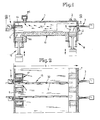
- 1 denotes a heating furnace, which is equipped on one side with an infeed device 11 and on the opposite side with an outfeed device 3.
- the conveying device 11 and the conveying device 3 are as shown by the side furnace walls 6 and 7 retractable and extendable roller tables.
- an inlet lifting hearth 12 which can be raised and lowered by means belonging to the state of the art and which is otherwise thermally sealed with respect to the interior of the furnace by corresponding water cup or sand cup seals.
- ceramic stove supports 5a are provided, which are arranged at a distance from one another and are in a gap with the rollers of the roller table of the conveying device 11.
- a lifting bench stove 18 is provided, which is also equipped with stove supports 5 made of ceramic material and can be raised and lowered.
- the actual storage chamber 10, which is designed as a ceramic fixed hearth, is provided between the conveying device 11 and the conveying device 3.
- the pre-strip to be treated is designated by 14 and dashed lines are shown in the storage chamber 10 pre-strips.
- the pre-heating 14 is reheated by burners 2 arranged in the wall of the heating furnace 1, while in the area of the feeding device 11 an exhaust duct 16 connects to the top of the heating furnace 1 , so that the exhaust gases flow through the storage chamber 10 in accordance with the arrows F and at the same time bring about a heating of the pre-strips 14 possibly stored in the storage chamber 10.
- the bottom of the storage chamber 10 extends from the right to the left side wall 6, 7 of the heating furnace 1 and 10 pocket slots 17 are provided in the area of the inlet lift 12 and the lifting bench 18 so that fixed hearth bridges 4 are created in this area.
- transverse tractor slots 9 are provided, in which transverse tractors 15 are arranged, which have vertically oriented drivers 30 and thus reach over the level of the floor of the storage chamber and thus the supporting strip 14 transversely, i. H. can convey from the infeed device 11 to the outfeed device 3, but can also undermine the pre-strips 14 already stored.
- the mode of operation of the heating furnace 1 shown in FIGS. 1 and 2 is as follows:
- the preliminary strip 14 is cut to the desired length by a cutting device and runs into the heating furnace 1 at an increased speed via the feed device 11 until the furnace position is reached. Then the feeding device 11 is stopped.
- the inlet lifting hearth 12 moves vertically upwards and lifts the preliminary strip 14 from the feeding device 11 via the stove supports 5a, which are in gap with the rollers of the feeding device 11. Then the infeed device 11, ie the rollers of this infeed device 11, is withdrawn from the side furnace wall 6, so that the supporting strip 14 is now carried by the stove supports 5a of the inlet lift stove 12. The inlet lift range 12 moves down and thereby places the supporting strip 14 on the fixed hearth bridges 4 formed between the key slots 17.
- the vertically adjustable catches 30 of the cross-tractor 15 grip the support 14 and convey this support 14 through the storage chamber 10 into the area of the lifting bench 18, so that the support 14 then lies on the fixed hearth bridges 4 provided in this area.
- the cross-tractors 15 move in the cross-tractor slots 9. Then the lifting bench hearth 18 lifts the support 14 over the hearth supports 5 from the fixed hearth bridges 4, at which point the outfeed device 3 is located outside the furnace.
- the supporting strip 14 carried by the lifting bench hearth 18 is heated on all sides by the burners 2, whereby - since the transverse tractor slots 9 are also in gap with the hearth supports 5 of the lifting bench cooker 18 - the cooling shadows which may be caused by the transverse tractor slots 9 are eliminated and the supporting strip 14 is applied on all sides the desired temperature is heated.
- the exhaust gases from the burners 2 flow through the storage chamber 10 to the exhaust duct 16 and at the same time the conveying device 11 is moved back into the heating furnace 1 and transports a new preliminary strip 14 into the furnace.
- the outfeed device 3 moves into the heating furnace 1, engages under the support plate 14 lying on the stove supports 5 and, after the bench seat 18 has been lowered, the outfeed device 3 promotes this Pre-strip 14 having the desired temperature to the roll stand.
- the pocket slots 17 can be rectangular, round or the like.
- the transverse tractor slots 9 (approximately four to six pieces seen over the length of the furnace) are formed in the ceramic fixed hearth.
- the transverse forces occurring during the transverse transport of the pre-strip 14 from the infeed device 11 to the outfeed device 3 cannot have an effect on the inlet lifting hearth 12 and the lifting bench hearth 18, since the hearth supports 5a and 5 are located below the level of the top of the storage chamber 10 or the ceramic fixed hearth, so that no wear can occur on the stove supports 5a and 5 made of ceramic material.
- the use of ceramic stove supports 5 and 5a ensures that the preliminary strip 14 is kept warm, particularly in the region of the lifting bench stove 18.
- pre-strips 14 can now be stored in the storage chamber 10 between the infeed device 11 and the outfeed device 3, as is shown in broken lines in FIG. 1. In the event of shorter disturbances, an interruption of the casting process is not necessary because the stored pre-strips 14 can be rolled by a shorter drawing cycle.
- a heating furnace 1 which can be fed by two continuous casting plants. For this reason, two infeed devices 11 are in the lateral furnace walls 6 and 7 and a middle discharge device 3. The final preheating of the pre-strips 14 thus takes place on the lifting bench range 18 arranged in the middle area of the heating furnace 1.
- this heating furnace 1 essentially corresponds to the mode of operation as was explained with reference to FIGS. 1 and 2.
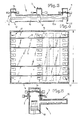
- the length of the heating furnace 1 is shown in Fig. 4 with 1 located substantially corresponds to the length of a pre-strip 14th
- the width b of the heating furnace can be seen in FIG.
- the actual storage chamber 10 is arranged on the side of the heating furnace 1 and the conveying device 11 and the conveying device 3 are designed as a two-tier roller table.
- the operation of this heating furnace is such that the preliminary strip 14 shown on the conveying device 11 in FIG. 5 is raised, lowered and then reheated by lifting the lifting hearth 18, the burners 2 being arranged in the region of the conveying device 3 in FIG. 5.
- the outfeed device 3 is moved into the heating furnace, the pre-strip 14 is removed from the lifting hearth 18 and conveys it to the rolling mill.
- the heating furnaces 1 are equipped with inlet and outlet roller tables and 6 and 7 are in principle constructed in the same way as the furnace according to FIG. 1, but the preliminary strip 14 runs in this furnace construction through a door slot 24 into the heating furnace 1 and is thereby via a towing device 19 drawn into the heating furnace 1 and supported by the ceramic stove of the storage chamber.
- a drag slot 19a is provided for the towing device 19, and either a driver 21 or a clamp lock is used to connect the towing device 19 to the supporting strip 14. If a towing device 19 with a vertically movable driver 21 is used, then a driver opening 25 must be cut into the preliminary strip 14, into which the driver 21 can snap.
- the pre-strip 14 is separated from the main strip outside of the heating furnace 1 and brought into the furnace end position by the towing device 19 at an increased speed. As long as the pre-strip 14 has not yet been separated from the main strip, the towing device 19 runs in at the speed of the main strip, which is determined by the caster.
- the sliver 14 is pushed onto the ceramic fixed hearth of the storage chamber 10 equipped with transverse tractor slots 9 and then conveyed from the transverse tractors to the fixed hearth bridges 4 in the area of the hearth supports 5 of the lifting bench stove 18.
- the lifting bench hearth 18 lifts the support strip 14 and the reheating then also takes place here about the burner 2 shown (Fig. 6).
- the sliver 14 is placed on the fixed hearth bridges 4 by lowering the lifting bench 18 and the tractors convey the sliver 14 to a run-out path, which is generally designated by 26.
- This run-out path 26 can consist of heat-resistant cast plates 23 which are connected to the ceramic fixed hearth by suitable holding devices. Compared to steel / ceramic friction, the steel / steel friction considerably reduces the coefficient of friction. This means that less tractive effort is required for the opening of the pre-strip.
- tractor slot 20 only has to be very short, so that there is no great heat loss here, since the supporting strip 14 can be gripped in the area of the tractor slot 20 and then pulled out while the towing device 19 extends over the entire length of the furnace got to.
- an outlet door slot 28 can also be closed by appropriate doors when not in use and thus secured against heat loss.
- the pre-strips 14 are stored in the storage chamber 10, as shown in broken lines in FIG. 6, and then rolled. By reheating the pre-strip 14 on the raised lifting bench 18, the cooling shadows caused by the tractor slots 15 and possibly 9 are eliminated. The preliminary strip 14 is reheated very evenly with low heat consumption.
- the use of the furnace construction according to the invention guarantees a principle of the method by which storage spaces between the conveying device and the discharging device can be achieved, with a rapid transport of the preliminary strip through the normally empty storage chamber 10.
- the area of the lifting bench 18 there is all-round heating of the supporting strip 14 carried there by the ceramic stove supports in the raised state, also outside the influence of the cooling shadow of the transport element slots or other water- or air-cooled transport devices.
- a simple allocation and a simple reduction of the storage spaces is achieved, so that the furnace can be optimally designed for every application.
- one or more continuous casting plants can connect to a furnace and work.
Landscapes
- Engineering & Computer Science (AREA)
- Mechanical Engineering (AREA)
- General Engineering & Computer Science (AREA)
- Tunnel Furnaces (AREA)
Applications Claiming Priority (2)
| Application Number | Priority Date | Filing Date | Title |
|---|---|---|---|
| DE3832004 | 1988-09-21 | ||
| DE19883832004 DE3832004C1 (fr) | 1988-09-21 | 1988-09-21 |
Publications (2)
| Publication Number | Publication Date |
|---|---|
| EP0359977A2 true EP0359977A2 (fr) | 1990-03-28 |
| EP0359977A3 EP0359977A3 (fr) | 1991-07-31 |
Family
ID=6363376
Family Applications (1)
| Application Number | Title | Priority Date | Filing Date |
|---|---|---|---|
| EP19890114784 Withdrawn EP0359977A3 (fr) | 1988-09-21 | 1989-08-10 | Four de traitement thermique pour une installation de coulée ébauche |
Country Status (2)
| Country | Link |
|---|---|
| EP (1) | EP0359977A3 (fr) |
| DE (1) | DE3832004C1 (fr) |
Cited By (1)
| Publication number | Priority date | Publication date | Assignee | Title |
|---|---|---|---|---|
| EP0682770A4 (fr) * | 1993-02-03 | 1996-01-17 | Bricmanage Inc | Systeme de four de chauffage et procede de production de pieces a usiner laminees a chaud. |
Family Cites Families (4)
| Publication number | Priority date | Publication date | Assignee | Title |
|---|---|---|---|---|
| DE3422922C1 (de) * | 1984-06-20 | 1985-06-20 | Korf-BSW Engineering GmbH, 7640 Kehl | Anlage mit einem Waermofen fuer auf Laenge geschnittene Strangstuecke einer Stranggiessanlage |
| GB8620583D0 (en) * | 1986-08-23 | 1986-10-01 | British Steel Corp | Processing steel slabs |
| ATE46463T1 (de) * | 1986-10-13 | 1989-10-15 | Schloemann Siemag Ag | Herstellung von warmgewalztem stahlband aus stranggegossenen brammen. |
| DE3740619C1 (en) * | 1987-12-01 | 1988-12-22 | Didier Eng | Heating furnace for a roughed-strip casting installation |
-
1988
- 1988-09-21 DE DE19883832004 patent/DE3832004C1/de not_active Expired - Fee Related
-
1989
- 1989-08-10 EP EP19890114784 patent/EP0359977A3/fr not_active Withdrawn
Cited By (1)
| Publication number | Priority date | Publication date | Assignee | Title |
|---|---|---|---|---|
| EP0682770A4 (fr) * | 1993-02-03 | 1996-01-17 | Bricmanage Inc | Systeme de four de chauffage et procede de production de pieces a usiner laminees a chaud. |
Also Published As
| Publication number | Publication date |
|---|---|
| DE3832004C1 (fr) | 1990-01-25 |
| EP0359977A3 (fr) | 1991-07-31 |
Similar Documents
| Publication | Publication Date | Title |
|---|---|---|
| DE3132373A1 (de) | Ofen zum erwaermen von brammen, knueppeln und rohlingen | |
| CH632698A5 (de) | Anlage zur herstellung von gebrannten ziegelrohlingen. | |
| EP0236666B1 (fr) | Procédé de réchauffage de produits semi-finis provenant d'installations de coulée continue ou d'installations de formage en vue de leur chargement dans des installations de formage ou de finissage | |
| DE68918531T2 (de) | Anlage zum Walzen flacher Produkte. | |
| DE2712279C2 (de) | Einrichtung zur Wärmebehandlung von zu behandelndem Gut, wie gegossenen Strängen und Barren, sowie Blöcken, Stangen, Rohren und dgl. insbesondere aus Aluminium- oder Magnesiumlegierungen | |
| DE1005904B (de) | Vorrichtung zum Stapeln oberflaechenempfindlicher Bleche | |
| EP0313726B1 (fr) | Procédé et four pour le chauffage de brames, billettes, lingots, tôles, bandes d'acier et de charges similaires | |
| DE3708050C2 (fr) | ||
| AT396559B (de) | Brammen-stranggiessanlage mit nachgeordnetem walzwerk | |
| DE2846818C2 (de) | Vorrichtung zum Aufheizen von kalten und/oder warmen Stahlblöcken | |
| DE102007016100A1 (de) | Einrichtung zum Warmhalten von aus einer Stranggießanlage austretenden Brammen | |
| DD262847A5 (de) | Verfahren und einrichtung zum ausbauchen einer glasplatte | |
| DE3545498C2 (fr) | ||
| DE3832004C1 (fr) | ||
| EP0093877B1 (fr) | Dispositif pour le traitement thermique de pièces de matière à haute température | |
| EP3757496A1 (fr) | Installation de four tunnel à rouleaux et procédé de chauffage des blancs en acier revêtus d'aluminium, de silicium et/ou de zinc à la température de durcissement et de pression | |
| DE69805474T2 (de) | Anlage zur Behandlung von siderurgischen Produkten | |
| DE3736674C1 (en) | Method and furnace for heating slabs, ingots, billets, sheets and similar products | |
| DE3830027C2 (fr) | ||
| EP2778588B1 (fr) | Four pour le frittage des articles céramiques | |
| DE102009053343B4 (de) | Stoßofen, Ofenanlage und thermisches Behandlungsverfahren | |
| WO2011101231A1 (fr) | Dispositif de transport pour brames, doté d'au moins deux machines de coulée et d'au moins trois éléments transbordeurs | |
| DE866496C (de) | Vorrichtung zur selbsttaetigen Zufuehrung von Werkstuecken zu einer Induktionsheizeinrichtung | |
| DE3842290C1 (en) | Heating furnace for billets, ingots, slabs, rough strips and similar products to be heated | |
| DE69204102T2 (de) | Hubbalkenofen mit zentraler Ladung zum Beheizen und Speichern von Warmgut. |
Legal Events
| Date | Code | Title | Description |
|---|---|---|---|
| PUAI | Public reference made under article 153(3) epc to a published international application that has entered the european phase |
Free format text: ORIGINAL CODE: 0009012 |
|
| AK | Designated contracting states |
Kind code of ref document: A2 Designated state(s): AT BE DE ES SE |
|
| PUAL | Search report despatched |
Free format text: ORIGINAL CODE: 0009013 |
|
| AK | Designated contracting states |
Kind code of ref document: A3 Designated state(s): AT BE DE ES SE |
|
| STAA | Information on the status of an ep patent application or granted ep patent |
Free format text: STATUS: THE APPLICATION IS DEEMED TO BE WITHDRAWN |
|
| 18D | Application deemed to be withdrawn |
Effective date: 19920201 |