EP0360024B1 - Ferrure pour battant pivotant, ou pivotant et basculant, de fenêtres, portes ou similaires - Google Patents
Ferrure pour battant pivotant, ou pivotant et basculant, de fenêtres, portes ou similaires Download PDFInfo
- Publication number
- EP0360024B1 EP0360024B1 EP89115649A EP89115649A EP0360024B1 EP 0360024 B1 EP0360024 B1 EP 0360024B1 EP 89115649 A EP89115649 A EP 89115649A EP 89115649 A EP89115649 A EP 89115649A EP 0360024 B1 EP0360024 B1 EP 0360024B1
- Authority
- EP
- European Patent Office
- Prior art keywords
- frame
- pivot
- fixed frame
- fitting according
- leaf
- Prior art date
- Legal status (The legal status is an assumption and is not a legal conclusion. Google has not performed a legal analysis and makes no representation as to the accuracy of the status listed.)
- Expired - Lifetime
Links
- 238000006073 displacement reaction Methods 0.000 claims abstract description 4
- 238000009434 installation Methods 0.000 description 10
- 238000010276 construction Methods 0.000 description 5
- 238000005452 bending Methods 0.000 description 2
- 125000006850 spacer group Chemical group 0.000 description 2
- 238000003780 insertion Methods 0.000 description 1
- 230000037431 insertion Effects 0.000 description 1
- 238000012423 maintenance Methods 0.000 description 1
- 238000004519 manufacturing process Methods 0.000 description 1
- 239000000463 material Substances 0.000 description 1
- 239000013641 positive control Substances 0.000 description 1
- 230000000717 retained effect Effects 0.000 description 1
- 239000007787 solid Substances 0.000 description 1
Images
Classifications
-
- E—FIXED CONSTRUCTIONS
- E05—LOCKS; KEYS; WINDOW OR DOOR FITTINGS; SAFES
- E05F—DEVICES FOR MOVING WINGS INTO OPEN OR CLOSED POSITION; CHECKS FOR WINGS; WING FITTINGS NOT OTHERWISE PROVIDED FOR, CONCERNED WITH THE FUNCTIONING OF THE WING
- E05F7/00—Accessories for wings not provided for in other groups of this subclass
- E05F7/06—Devices for taking the weight of the wing, arranged away from the hinge axis
-
- E—FIXED CONSTRUCTIONS
- E05—LOCKS; KEYS; WINDOW OR DOOR FITTINGS; SAFES
- E05D—HINGES OR SUSPENSION DEVICES FOR DOORS, WINDOWS OR WINGS
- E05D15/00—Suspension arrangements for wings
- E05D15/28—Suspension arrangements for wings supported on arms movable in horizontal plane
- E05D15/32—Suspension arrangements for wings supported on arms movable in horizontal plane with two pairs of pivoted arms
-
- E—FIXED CONSTRUCTIONS
- E05—LOCKS; KEYS; WINDOW OR DOOR FITTINGS; SAFES
- E05D—HINGES OR SUSPENSION DEVICES FOR DOORS, WINDOWS OR WINGS
- E05D15/00—Suspension arrangements for wings
- E05D15/48—Suspension arrangements for wings allowing alternative movements
- E05D15/52—Suspension arrangements for wings allowing alternative movements for opening about a vertical as well as a horizontal axis
- E05D15/5211—Concealed suspension fittings
-
- E—FIXED CONSTRUCTIONS
- E05—LOCKS; KEYS; WINDOW OR DOOR FITTINGS; SAFES
- E05D—HINGES OR SUSPENSION DEVICES FOR DOORS, WINDOWS OR WINGS
- E05D7/00—Hinges or pivots of special construction
- E05D7/04—Hinges adjustable relative to the wing or the frame
- E05D7/0415—Hinges adjustable relative to the wing or the frame with adjusting drive means
- E05D7/0423—Screw-and-nut mechanisms
-
- E—FIXED CONSTRUCTIONS
- E05—LOCKS; KEYS; WINDOW OR DOOR FITTINGS; SAFES
- E05D—HINGES OR SUSPENSION DEVICES FOR DOORS, WINDOWS OR WINGS
- E05D15/00—Suspension arrangements for wings
- E05D15/28—Suspension arrangements for wings supported on arms movable in horizontal plane
- E05D15/30—Suspension arrangements for wings supported on arms movable in horizontal plane with pivoted arms and sliding guides
-
- E—FIXED CONSTRUCTIONS
- E05—LOCKS; KEYS; WINDOW OR DOOR FITTINGS; SAFES
- E05D—HINGES OR SUSPENSION DEVICES FOR DOORS, WINDOWS OR WINGS
- E05D7/00—Hinges or pivots of special construction
- E05D7/04—Hinges adjustable relative to the wing or the frame
- E05D2007/0469—Hinges adjustable relative to the wing or the frame in an axial direction
-
- E—FIXED CONSTRUCTIONS
- E05—LOCKS; KEYS; WINDOW OR DOOR FITTINGS; SAFES
- E05Y—INDEXING SCHEME ASSOCIATED WITH SUBCLASSES E05D AND E05F, RELATING TO CONSTRUCTION ELEMENTS, ELECTRIC CONTROL, POWER SUPPLY, POWER SIGNAL OR TRANSMISSION, USER INTERFACES, MOUNTING OR COUPLING, DETAILS, ACCESSORIES, AUXILIARY OPERATIONS NOT OTHERWISE PROVIDED FOR, APPLICATION THEREOF
- E05Y2900/00—Application of doors, windows, wings or fittings thereof
- E05Y2900/10—Application of doors, windows, wings or fittings thereof for buildings or parts thereof
- E05Y2900/13—Type of wing
- E05Y2900/148—Windows
Definitions
- the invention relates to a turn fitting or turn-tilt fitting of windows, doors or the like according to the preamble of claim 1.
- Such a fitting is known (DE-B2-21 13 665, DE-C1-34 42 364, DE-A1-36 01 278, EP-A2-204 267, DE-A1-32 23 451, US-A-18 88 345).
- the handlebar construction provided on the upper and lower pivot bearing ensures that the pivot axis is displaced in front of the fixed frame when the sash frame is opened, so that a sash flap of the sash frame covering the rebate space between the fixed frame and sash frame when the sash frame is closed does not collide when the sash is opened comes with the fixed frame.
- all the fitting parts can be accommodated in the rebate space with the sash frame closed, that is to say covered by the sash flap, which ensures a pleasing exterior.
- a disadvantage of the known designs is in particular that the handlebars are exposed to considerable bending stresses with larger wing weights. This can lead to bending of the handlebars and thus to stiffness. the hardware becomes inoperative.
- GB-A-2086970 discloses a device for supporting the casement on the fixed frame, which is effective only when the window is closed, from a projection in the rebate space which is fixed in the casement frame and which penetrates into a casement opening. This device is neither intended nor suitable for supporting the revolving sash frame.
- the invention has for its object to provide a fitting of the type mentioned, which ensures reliable function even with larger leaf weights with a compact structure.
- This object is achieved in that the sash frame, at least when the sash frame is open for rotation, is supported on the fixed frame by a device which is independent of the links of the two pivot bearings.
- the device could be formed, in particular in the case of a pure rotary fitting, by an element acting between the sash frame and the fixed frame and thereby being subjected to tension.
- the device comprises a support rod which is supported at one end on the fixed frame in the region of the lower pivot bearing and at the other end on the frame leg of the casement frame which is close to the pivot bearing and is parallel to the axis of rotation.
- the support rod which is loaded under pressure, transfers the wing forces to the lower corner bearing when opening and turning, relieving the strain on the handlebars of the two pivot bearings.
- the support rod can be retained unchanged even when the sash is opened.
- the support rod is supported on an angled support tab of a frame-side corner bearing part, preferably on the vertical leg of a frame-side corner bearing angle.
- a particularly simple construction is ensured in that the support rod is mounted such that it can be tilted on the support tab. The support rod can then easily participate in the tilting movement of the wing.
- a simple structure in particular in the case of the usual fitting structure with a faceplate, ensures that the support rod is supported on a support bracket, which is preferably attached to a sash faceplate.
- the support angle is designed to be adjustable in the direction parallel to the axis of rotation, and that the support angle is supported on an adjusting screw.
- the support bracket is rotatably mounted.
- the support rod is captively attached to the support bracket and is preferably essentially rigid, a preassembly unit consisting of the support rod, support bracket and possibly faceplate is obtained without the risk of the support rod being lost.
- the support rod is provided at its lower end with a pin which can be inserted into a bore in the support tab and which preferably tapers conically towards the end of the pin.
- these measures make it easier to assemble the sash, since for this purpose the support rod pre-assembled on the sash frame is only to be inserted into the bore of the support flap; on the other hand, the preferred conical tapering of the pin end ensures that the support rod can perform the required tilting movements when opening or tilting the wing relative to the frame-fixed support tab.
- the support rod When the sash opens, the upper end of the support rod pivots around the lower frame-fixed support point.
- the support rod be supported at a location on the lower pivot bearing that consists of a central plane of the lower pivot bearing in parallel with the frame plane of the fixed frame Is offset towards the casement. Due to the displacement of the support point, there is a slight increase in the frame at the beginning of the opening movement until the support rod is vertical; the sash frame is lowered slightly in the course of the further opening movement.
- the two joints following the offset, the rotary joint and the sliding rotary joint can be arranged one above the other (in the direction parallel to the frame plane and perpendicular to the longitudinal directions of the handlebars); they can therefore also lie in a plane parallel to the frame plane, which permits a corresponding narrow construction of the handlebar arrangement with a small installation depth.
- the measure that at least one of the two links, preferably both links, is provided in the region of the respective offset with a recess open in the direction perpendicular to the plane of the frame for receiving the other link also contributes to this.
- the two handlebars have a width that is essentially the same as the desired installation depth (perpendicular to the frame plane) and are therefore sufficiently stable.
- a slight offset, corresponding to the thickness of a bearing pin head, is obtained in that the fixed frame-side pivot bearing part is provided with an offset corresponding to the thickness of a bearing pin head in the region of its sliding swivel joint, and in that the control link and the guide link each have an essentially identical offset are. This creates freedom of movement for the bearing bolt head without having to mill out the sash frame.
- a conical taper of the driver pin allows the tilting movement of the wing without the need for tiltable rivets, as are known, for example, from DE-A1-36 01 278, with the disadvantage of difficult manufacture with corresponding precision.
- the carrier part on the sash frame is designed to be adjustable in the direction parallel to the lower horizontal sash frame leg. It is preferably provided here that a stop angle is rigidly attached to the sash frame corner, the horizontal leg of which is formed with a sliding guide for the carrier part and the vertical leg of which is supported by an adjusting screw on an extension of the carrier part.
- This device can comprise an element which acts between the sash frame and the fixed frame and is loaded under tension.
- the device comprises a support rod which acts between the sash frame and the fixed frame and is loaded under pressure.
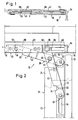
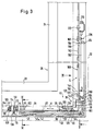
- the turn-tilt fitting to be described below with reference to the figures consists of an upper pivot bearing 10 shown in FIGS. 1 and 2, one in the following as Corner bearing 12 designated lower pivot bearing, which also serves as a tilting bearing, and a support device 160 for relieving the pivot bearing 10 and the corner bearing 12, in particular when the sash is open or pivoted.
- An upper horizontal leg 16 and a vertical leg 18 on the axis of rotation of a fixed frame 20 are indicated in FIG. 2.
- An upper horizontal leg 22 and a vertical leg 24 near the axis of rotation of a casement 26 can also be seen.
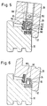
- a lower horizontal leg 28 of the casement and a lower horizontal leg 30 of the fixed frame 20 are shown in section in FIGS. 5 and 6.
- a circumferential sash overlap 32 which covers all fitting parts invisibly from the outside when the sash is closed, can be seen in FIGS. 2, 4, 5 and 6, and is indicated in FIG. 3 with a dash-dot outline.
- Each handlebar cross 38 consists of a guide link 40 and a control link 42, which are connected to one another via a simple pivot joint 44, hereinafter referred to as a universal joint 44, with a vertical pivot axis 46.
- the guide link 40 is connected to the fixed frame 20 via a swivel joint 48 with a vertical axis 50, and to the sash frame 26 likewise via a swivel joint 52 with a vertical axis 54.
- the axis 54 can be referred to as the axis of rotation of the leaf 26; it wanders when opening the rotary or closing the wing 26 along an arc 56 lying in the horizontal plane about the axis 50.
- the control link 42 is coupled to the fixed frame 20 or to the sash frame 26 via a sliding rotary joint 58 or 60.
- a sliding rotary joint 58 or 60 In the case of the upper swivel joint 10, an elongated hole 66 parallel to the longitudinal direction of the upper horizontal leg 16 of the fixed frame 20 is formed in the horizontal leg 62 of a screw-on angle (64) attached to the fixed frame, which extends into the area of the angle bend of the screw-on angle 64 and a guide pin 68 records. This protrudes from the top of the control arm 42 and overlaps the longitudinal edges of the elongated hole 66 with a bolt head 70. As shown in FIGS.
- the section of the leg 62 of the screw bracket 64 formed with the elongated hole 66 is downward in accordance with the thickness of the Bolt head 7 cranked.
- the frame rebate inner circumferential surface of the fixed frame 20 it is therefore not necessary to mill out the receptacle for the bolt head 70 which can be displaced along the elongated hole 66.
- the links 40 and 42, as well as in the case of the pivot bearing 10 also an extension arm 72 connected to the handlebars on the sash frame with corresponding offsets.
- the guide link 40 is provided in the area between the universal joint 44 and the pivot 48 with a laterally open recess 76 and with an offset 80 in this area corresponding to the material thickness of the two links 40 and 42, so that the one with a corresponding laterally open recess 74 and one Bend 82 in the same area, but with the opposite bend direction Control link 42 arrives in parallel position with guide link 40 when the wing is closed.
- the order of the guide and control link is then reversed after the bends 80, 82.
- the installation depth a corresponds to the guide link width c.
- the sliding rotary joint 60 on the raising arm 72 is formed with an elongated hole 84 extending in the longitudinal direction of the extending arm, in which in turn a guide pin 86 rigidly connected to the control link 42 is mounted so as to be longitudinally displaceable.
- control link 42 ensures that the guide link 40 and thus also the axis of rotation 54 assume a precisely defined spatial position at a certain opening angle.
- larger closing forces can be achieved if required.
- the opening arm 72 which is rigidly fixed to the sash when the sash is closed or rotatably opened is released so that it can be swiveled out of the sash frame level to a maximum opening angle in order to tilt open the window.
- the end of the raising arm 72 on the wing frame side can be movably attached in a sliding-rotation guide 6 on the wing frame with a limiting angle of extension by an auxiliary arm 3.
- the basic structure of the corner bearing 12 with respect to the handlebar 38 there corresponds to the configuration described above with reference to FIGS. 1 and 2. It is thereby achieved that the axis of rotation 54 of the wing defined by the two crossbars 38 (swivel joint of the guide link 40 on the wing frame side) remains vertically oriented or is always shifted in parallel.
- a corner bearing bracket 90 with a swivel joint 48 for the guide link 40 and sliding swivel joint 58 for a connection to the control link 42.
- a support part 92 which has an elongated hole recess, takes the place of the extension arm 72 94 is designed to receive a driver pin 96 protruding from the control link 42, and with a bore 98 for receiving a second driver pin 100 projecting from the guide link 40.
- the driver pin 100 is conically tapered towards the top to allow the wing to open tilting ( Fig. 5).
- the driver pin 96 is only tapered at its free end in order to facilitate insertion into the elongated hole 94 during wing assembly.
- it is cylindrical in shape to ensure solid mechanical guidance within the elongated hole 94 when the wing is opened.
- the elongated hole recess 94 is extended laterally at its end remote from the axis of rotation 54 in such a way that side windows 102 form.
- the driver pin 96 at least partially penetrates one of the two windows 102 (FIG. 6).
- the carrier part 92 can be designed to be displaceable on the sash frame 26 in the horizontal direction parallel to the sash frame plane (double arrow A in FIG. 3) in order to enable the setting of a rebate clearance between vertical frame legs of the fixed frame and the sash frame.
- the carrier part 92 is in the area its end remote from the axis of rotation is slidably attached to a support body 52 fixed to the casement.
- the support body 52 consists of a plate 108 lying in an outer groove step 104 of a correspondingly graduated sash frame groove 106, which is riveted to a reduced-diameter spacer bolt 110 with a subsequently enlarged collar 112.
- the spacer bolt 110 is provided with a through hole 114 into which a fastening screw, not shown in FIG. 3, can be inserted.
- the support part 92 is provided in the area of the support body 52 with mutually parallel recesses 115 and 116 on the top and bottom of the support part 92, for receiving the diameter-enlarged collar 112 and the plate 108.
- the bolt 110 is in one between the two recesses 115, 116 extending slot 118 mounted in the direction of the double arrow A slidably.
- the carrier part 92 is also mounted on a stop bracket 120 in the direction A.
- the stop bracket 120 covers the corresponding wing frame corner to which it is rigidly screwed (through opening 122 for the fastening screw, not shown).
- a pin projection 126 projecting downward on the horizontal leg 124 of the stop bracket 122 serves as a linear guide for the carrier part 92.
- it is riveted, for example, to a ring 128 with an enlarged diameter at its lower end.
- This ring 128 penetrates an elongated hole 130 in a bottom 132 of the support part 92 which is designed like a trough in this area.
- the top of the ring 128 lies against the underside of two webs 134 which extend along the longitudinal edges of the elongated hole.
- the carrier part 92 is formed with an extension 140 projecting upwards, which receives both the already mentioned downwardly open bore 98 and one horizontally extending adjusting screw 142 (indicated by dashed lines in Fig. 3) cooperates, which is additionally supported on the vertical leg 144 of the stop bracket 120.
- the adjusting screw 142 can be fixed, for example, rotatably, but axially immovably on the vertical leg 144 and cooperate with its external thread with an internal thread provided in the extension. A rotation of the adjusting screw 142 results in a corresponding displacement of the carrier part 92 in one direction or the other (double arrow A).
- a fastening screw 152 indicated in FIG. 5 can be used for this purpose, which penetrates both the faceplate 150 and the vertical leg 122. 5 also shows the adjusting screw 142 and the bore 98 receiving the pin 100 when the sash is open. A circumferential seal 154 attached to the casement provides a seal between the casement and the fixed frame when the casement is closed.
- FIG. 6 shows how the pin 96 partially penetrates one of the two windows 102 when the sash is open.
- a pin 156 indicated in FIG. 3 at the left end of the corner bearing bracket 90 and projecting upwards can be connected to an opening rod which limits the rotation-opening angle and is provided between the fixed frame and the sash frame and can serve as a locking pin.
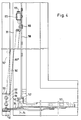
- the support device 160 In order to relieve the two handlebar crosses 38 of the sash weight, in particular when the sash is open and pivoted, the support device 160, which can be seen in FIGS. 3 and 4 and which acts between the sash frame 26 and the fixed frame 20, is provided. This is formed by a support rod 162 which is supported with its upper end on a sash bracket 164 on the casement side and with its lower end on the corner bearing bracket 90.
- the support bracket 164 is slidably mounted on the vertical faceplate 150 in the vertical direction. This is indicated in FIG. 3 by a faceplate elongated hole 166 which passes through a guide pin 168 protruding from the support bracket 164 in the horizontal direction.
- the upper end of the vertical leg of the support bracket 164 is supported on an adjusting screw 170, which in turn passes through an abutment 172 rigidly attached to the faceplate 150.
- the support rod 162 is rigidly connected to the horizontal leg 174 of the support bracket 164, in particular by appropriate riveting.
- the mentioned bolt 168 allows the support bracket to pivot about the bolt axis 176. Such a pivoting movement occurs when the sash is rotated, as will be explained in the following.
- the upper end of the vertical leg 178 of the corner bracket 90 is formed with an inwardly angled support tab 180 (towards the casement 26), which in turn is provided with a bore 192 for receiving a pin 194 at the lower end of the support rod 162.
- the bore 192 in the support tab 180 is laterally offset from the longitudinal center plane 196 of the corner bracket 90 in the direction of the casement.
- the pin 194 and / or the bore 192 is correspondingly conical in order to permit the tilting movement of the support rod 162 that occurs when the screw is opened.
- the upper end of the support rod 162 is located approximately in the longitudinal median plane 196. This results in the starting position 162 ′ of the support rod, indicated in FIG. 4 with a broken outline, slightly inclined to the left. If the sash is now opened for rotation, the support rod 162 finally pivots into the position 162 ⁇ inclined to the right in FIG. 4, the support rod now being oriented vertically. The result is that the sash frame, which is supported on the support rod 160, subsequently performs a slight lowering movement when the sash is rotated and opened after an initial slight lifting movement. The two handlebar crosses 38 are always relieved of the wing weight.
- the fitting of the fitting described above is expediently carried out as follows:
- the carrier part 92 is mounted on the support body 52 and the stop bracket 120 with the aid of corresponding fastening screws in the lower corner region of the casement 26.
- the faceplate 150 together with support device 160 (support bracket 164 with support rod 162; abutment 172 including adjusting screw 170) is fixed in the vertical outer groove step. It has proven to be sensible to first turn the adjusting screw 170 down until the adjustment path of the support bracket 164 is exhausted.
- the screw-on bracket 64 together with the handlebar 38 and the raising arm 72 are mounted, the end of the raising arm not shown on the sash frame being initially not yet connected to the upper edge of the wing.
- the fixed frame-side corner bracket 90 together with the handlebar 38 is mounted.
- the lower guide link 42 is pivoted out by approximately 60-90%, so that the driver pin 100 extends into the plane of the drawing in FIG. 3 perpendicular direction in front of the angled support tab 180.
- the support rod 162 is then inserted with its lower pin 194 into the bore 192 of the support tab 180, as a result of which the sash frame is then supported on the corner bearing bracket 90 via the support device 160.
- the sash frame is now lowered until the driver pin 100 dips into the bore 98 and the driver pin 96 into the elongated hole recess 94.
- the extension arm 72 is then fixed on the upper wing edge. This can be done by turning a hammer head, not shown, attached to a latchable tab on the sash arm end.
- the sash frame In the open-turn position, the sash frame can be adjusted using the adjusting screw 142.
- the angled support tab 180 in conjunction with the extension 140 opposite it in the downward direction, forms an anti-lift device for the sash frame which is in the tilted position.
- control arms and control arms are largely relieved of the sash weight.
- the wing is inevitably pressed against the frame when it is closed, so that pressing lugs on the extension arm, which engage in recesses on the inside or rear frame, can be omitted. No additional locking in the area of the corner bearing is required.
- the sash In the swivel-open position, the sash can simply be lifted out for assembly or maintenance purposes. In the tilt position, however, the casement is secured against lifting.
- the wing When the wing is closed it is from only the operating handle is visible to the fittings, which contributes to an improved appearance.
- the two handlebar crosses require little installation space.
Landscapes
- Engineering & Computer Science (AREA)
- Mechanical Engineering (AREA)
- Hinges (AREA)
- Wing Frames And Configurations (AREA)
- Closing And Opening Devices For Wings, And Checks For Wings (AREA)
- Lighting Device Outwards From Vehicle And Optical Signal (AREA)
Claims (22)
- Ferrure à la française ou ferrure oscillo-battante de fenêtres, portes ou similaires comportant un châssis fixe (20) et un châssis ouvrant (26), qui est monté sur le châssis fixe (20), de manière à pouvoir tourner autour d'un axe vertical (54) et, dans le cas d'une ferrure oscillo-battante, peut basculer autour d'un axe de basculement horizontal, comprenant- un palier de rotation inférieur, qui relie le châssis fixe (20) dans la zone d'un angle inférieur de ce châssis fixe (20) au châssis ouvrant (26), et ce dans le cas d'une ferrure oscillo-battante, sous la forme d'un palier de rotation et de basculement (12),- un palier de rotation supérieur (10), qui relie le châssis fixe (20) dans la zone d'un angle supérieur de ce châssis fixe (20), dans le cas d'une ferrure à la française, avec le châssis ouvrant (26) et dans le cas d'une ferrure oscillo-battante, avec un bras de projection (72) accouplé au châssis ouvrant (26), les deux paliers de rotation (10, 12) comprenant chacun au moins deux bras oscillants (40, 42) pour le déplacement de l'axe de rotation (54) lors de l'ouverture par rotation du châssis ouvrant (26) dans une direction perpendiculaire au plan du châssis fixe (20),caractérisée en ce que le châssis ouvrant (26), au moins dans sa position ouverte par rotation, prend appui sur le châssis fixe (20), par un dispositif (160) indépendant des bras oscillants (40, 42) des deux paliers de rotation (10, 12).
- Ferrure selon la revendication 1, caractérisée en ce que le dispositif (160) comprend une barre d'appui (162) qui prend appui d'une part à une extrémité sur le châssis fixe (20), dans la zone du palier de rotation inférieur et, à l'autre extrémité, sur le côté (24) du châssis ouvrant (26), proche du palier de rotation, parallèle à l'axe de rotation (54).
- Ferrure selon la revendication 2, caractérisée en ce que la barre d'appui (162) prend appui sur une patte d'appui coudée (180) d'un élément de palier d'angle côté châssis, de préférence sur la branche verticale d'une équerre d'appui d'angle (90) côté chassis, dans le cas d'une ferrure oscillo-battante avec montage basculant de la barre d'appui (162) sur la patte d'appui (180).
- Ferrure selon la revendication 3, caractérisée en ce que, dans le cas où le châssis ouvrant est fermé, la patte d'appui (180) fait face, en direction de l'axe de rotation (54), à un prolongement (140) situé dans la zone de l'angle inférieur correspondant du châssis ouvrant.
- Ferrure selon l'une des revendications 2 à 4, caractérisée en ce que la barre d'appui (162) prend appui sur une équerre d'appui (164).
- Ferrure selon la revendication 5, caractérisée en ce que l'équerre (164) est fixée sur un rail à emboîtement (150) du châssis ouvrant.
- Ferrure selon la revendication 5 ou 6, caractérisée en ce que l'équerre d'appui (164) est déplaçable parallèlement à l'axe de rotation (54).
- Ferrure selon la revendication 7, caractérisée en ce que l'équerre d'appui (164) prend appui contre une vis de réglage (170).
- Ferrure selon l'une des revendications 5 à 8, caractérisée en ce que l'équerre d'appui (164) est montée tournante.
- Ferrure selon la revendication 9, caractérisée en ce que la barre d'appui (162) est fixée de façon imperdable sur l'équerre d'appui (164).
- Ferrure selon la revendication 10, caractérisée en ce que la barre d'appui (162) est fixée sensiblement rigidement sur l'équerre d'appui (164).
- Ferrure selon l'une au moins des revendications 3 à 11, caractérisée en ce que la barre d'appui (162) est pourvue à son extrémité inférieure d'un tenon (194) qui peut être inséré dans un trou (192) de la patte d'appui (180).
- Ferrure selon la revendication 12, caractérisée en ce que le tenon (194) se rétrécit coniquement vers son extrémité.
- Ferrure selon l'une au moins des revendications 3 à 13, caractérisée en ce que la barre d'appui (162) prend appui en un point du palier de rotation inférieur, qui est décalé, à partir d'un plan médian (196) du palier d'appui inférieur, parallèle au plan du châssis fixe, en direction du châssis ouvrant (26).
- Ferrure selon l'une au moins des revendications précédentes, dans laquelle les deux bras oscillants de chaque palier de rotation se croisent et sont reliés par articulation, au point de croisement, au moyen d'une articulation à croisillon (44) et dans laquelle l'un des deux bras oscillants, le bras de guidage (40), est relié à un élément de palier de rotation (64, 90) côté châssis fixe et à un élément de palier de rotation (92) côté châssis ouvrant ou à un bras de projection (72), dans chaque cas au moyen d'une articulation de rotation (48, 52) et l'autre bras oscillant, le bras de commande (42), est relié à l'élément de palier de rotation (64, 90) côté chassis fixe et à l'élément de palier de rotation (92) côté châssis ouvrant ou au bras de projection (72), dans chaque cas au moyen d'une articulation de rotation et de coulissement (58, 60), caractérisée en ce que, dans le cas où le battant est fermé, toutes les articulations de rotation (48, 52) ainsi que les articulations de rotation et de coulissement (58, 60) se situent au moins approximativement dans un plan parallèle au plan du châssis, en ce que le bras oscillant de commande (42) présente, dans la zone comprise entre l'articulation à croisillon (44) et l'une des deux articulations de rotation (48, 52), un coude dirigé vers l'élément de palier de rotation, portant l'articulation de rotation concernée, suivant l'épaisseur du bras oscillant de guidage (40) et en ce que le bras oscillant de guidage (40) présente également un coude suivant l'épaisseur du bras oscillant de commande, mais dirigé en sens opposé, qui, lorsque le battant est fermé dans une direction perpendiculaire au plan du châssis, se situe à côté du coude du bras oscillant de commande (42).
- Ferrure selon la revendication 15, caractérisée en ce que l'un au moins des deux bras oscillants (40, 42), de préférence les deux, est/sont pourvu(s) dans la zone du coude respectif d'un évidement (74, 76) ouvert perpendiculairement au plan du châssis, destiné à recevoir l'autre bras oscillant.
- Ferrure selon la revendication 15 ou 16, caractérisée en ce que l'élément de palier de rotation (64, 90), côté châssis fixe, est pourvu, dans la zone de son articulation de rotation et de coulissement (58), d'un coude suivant l'épaisseur d'une tête d'axe de palier (70) et en ce que le bras oscillant de commande (42) ainsi que le bras oscillant de guidage (40) présentent chacun un coude sensiblement similaire.
- Ferrure selon l'une au moins des revendications 15 à 17, caractérisée en ce que pour le palier oscillo-battant (palier d'angle 12), il est prévu, dans la zone de l'extrémité côté châssis ouvrant du bras oscillant de commande (42) et/ou du bras oscillant de guidage (40), un tenon d'entraînement (96, 100), qui s'engage dans une ouverture réceptrice de tenon (94, 98) correspondante d'un élément porteur (92) côté châssis ouvrant.
- Ferrure selon la revendication 18, caractérisée en ce que le tenon d'entraînement (100) se rétrécit coniquement vers son extrémité.
- Ferrure selon la revendication 18 ou 19, caractérisée en ce que l'élément porteur (92) est réglable sur le châssis ouvrant (26) dans une direction (A) parallèle au côté horizontal inférieur (28), du châssis ouvrant.
- Ferrure selon la revendication 20, caractérisée en ce que dans l'angle du châssis ouvrant il est fixé rigidement une équerre de butée (120) dont la branche horizontale (124) présente un guidage coulissant pour l'élément porteur (92) et dont la branche verticale (122) prend appui, par l'intermédiaire d'une vis de réglage (142), contre un prolongement (140) de l'élément porteur (92).
- Fenêtre ou porte ou similaire, comportant :- un châssis fixe (20),- un châssis ouvrant (26), qui est monté tournant sur le châssis fixe (20), autour d'un axe de rotation (54) vertical,- un palier de rotation inférieur (12), qui accouple le châssis fixe (20), dans la zone d'un angle inférieur de ce châssis fixe (20), avec le châssis ouvrant,- un palier de rotation supérieur (10), qui accouple le châssis fixe (20), dans la zone d'un angle supérieur de ce châssis fixe (20), avec le châssis ouvrant (26), les deux paliers de rotation (10, 12) présentant chacun au moins deux bras oscillants (40, 42) pour le déplacement de l'axe de rotation (54) lors de l'ouverture par rotation du châssis ouvrant (26),caractérisée en ce que
le châssis ouvrant (26) prend appui sur le châssis fixe (20), au moins lorsque le châssis ouvrant (26) est ouvert par rotation, par l'intermédiaire d'un dispositif (160) indépendant des bras oscillants (40, 42) des deux paliers de rotation (10, 12), lequel dispositif est logé dans la feuillure lorsque le châssis ouvrant (26) est fermé.
Priority Applications (1)
| Application Number | Priority Date | Filing Date | Title |
|---|---|---|---|
| EP93121129A EP0598419B2 (fr) | 1988-08-26 | 1989-08-24 | Ferrure d'articulation ou oscillo-battante de fenêtres, portes ou analogues |
Applications Claiming Priority (2)
| Application Number | Priority Date | Filing Date | Title |
|---|---|---|---|
| DE3829053A DE3829053C2 (de) | 1988-08-26 | 1988-08-26 | Dreh-Beschlag oder Dreh-Kipp-Beschlag von Fenstern, Türen oder dergleichen |
| DE3829053 | 1988-08-26 |
Related Child Applications (2)
| Application Number | Title | Priority Date | Filing Date |
|---|---|---|---|
| EP93121129A Division EP0598419B2 (fr) | 1988-08-26 | 1989-08-24 | Ferrure d'articulation ou oscillo-battante de fenêtres, portes ou analogues |
| EP93121129.6 Division-Into | 1993-12-30 |
Publications (2)
| Publication Number | Publication Date |
|---|---|
| EP0360024A1 EP0360024A1 (fr) | 1990-03-28 |
| EP0360024B1 true EP0360024B1 (fr) | 1995-03-22 |
Family
ID=6361677
Family Applications (2)
| Application Number | Title | Priority Date | Filing Date |
|---|---|---|---|
| EP89115649A Expired - Lifetime EP0360024B1 (fr) | 1988-08-26 | 1989-08-24 | Ferrure pour battant pivotant, ou pivotant et basculant, de fenêtres, portes ou similaires |
| EP93121129A Expired - Lifetime EP0598419B2 (fr) | 1988-08-26 | 1989-08-24 | Ferrure d'articulation ou oscillo-battante de fenêtres, portes ou analogues |
Family Applications After (1)
| Application Number | Title | Priority Date | Filing Date |
|---|---|---|---|
| EP93121129A Expired - Lifetime EP0598419B2 (fr) | 1988-08-26 | 1989-08-24 | Ferrure d'articulation ou oscillo-battante de fenêtres, portes ou analogues |
Country Status (4)
| Country | Link |
|---|---|
| US (1) | US5052079A (fr) |
| EP (2) | EP0360024B1 (fr) |
| AT (2) | ATE153732T1 (fr) |
| DE (3) | DE3829053C2 (fr) |
Cited By (6)
| Publication number | Priority date | Publication date | Assignee | Title |
|---|---|---|---|---|
| EP1837472A1 (fr) | 2006-03-25 | 2007-09-26 | Roto Frank Ag | Fenêtre, porte ou similaire avec un dispositif de délestage |
| DE102007024742A1 (de) | 2007-05-26 | 2008-11-27 | Roto Frank Ag | Fenster, Tür oder dergleichen mit einer Entlastungseinrichtung |
| CN1715605B (zh) * | 2004-06-28 | 2010-05-26 | 萨维奥股份有限公司 | 用于翼式和旋转翼式打开的窗和门的隐式铰接装置 |
| DE202009006565U1 (de) | 2009-05-07 | 2010-09-23 | Siegenia-Aubi Kg | Beschlag |
| EP2481874A2 (fr) | 2011-02-01 | 2012-08-01 | Aug. Winkhaus GmbH & Co. KG | Ferrure oscillo-battante |
| DE102012216058A1 (de) | 2012-09-11 | 2014-03-13 | Aug. Winkhaus Gmbh & Co. Kg | Lastabtrageinrichtung für einen gegen einen Rahmen schwenkbaren Flügel |
Families Citing this family (33)
| Publication number | Priority date | Publication date | Assignee | Title |
|---|---|---|---|---|
| DE3943455C2 (de) * | 1989-01-24 | 1996-05-30 | Siegenia Frank Kg | Fenster oder Tür mit Drehkippflügel |
| DE9000152U1 (de) * | 1990-01-09 | 1990-03-15 | August Bilstein GmbH & Co KG, 5828 Ennepetal | Unteres Ecklager für Dreh-, insbesondere Dreh/Kipp-Fenster, -Türen od.dgl. |
| DE4117407C2 (de) * | 1991-05-28 | 1995-01-05 | Bilstein August Gmbh Co Kg | Drehkippbeschlag |
| DE4303286C2 (de) * | 1993-02-05 | 1997-04-10 | Aubi Baubeschlaege Gmbh | Drehkipp-Ecklager |
| DE9303579U1 (de) * | 1993-03-15 | 1994-07-14 | Siegenia-Frank Kg, 57074 Siegen | Fenster oder Tür |
| DE4414523A1 (de) * | 1994-04-26 | 1995-11-02 | Winkhaus Fa August | Dreh-Beschlag oder Dreh-Kipp-Beschlag von Fenstern, Türen oder dergleichen |
| DE4434510A1 (de) * | 1994-09-27 | 1996-03-28 | Winkhaus Fa August | Dreh-Beschlag oder Dreh-Kipp-Beschlag von Fenster, Türen oder dergleichen mit verrastbarem Exzenterteil zum Einstellen einer horizontalen Falzluft und/oder eines Flügelanpreßdrucks zwischen Festrahmen und Flügelrahmen |
| DE4439463C1 (de) * | 1994-11-04 | 1996-06-05 | Bilstein August Gmbh Co Kg | Entlastungselement |
| GB2304148B (en) * | 1995-08-11 | 1999-08-04 | Jason David Paddock | Hinge mechanisms for openable windows and other such movable panels |
| DE19533930C2 (de) * | 1995-09-13 | 1997-07-31 | Pobloth Alfred Dr Med | Scharnier zum drehbaren Verbinden von Türen, Fenstern oder Klappen mit Zarge oder Schrankkörper über zwei Drehachsen |
| FR2752010B1 (fr) * | 1996-07-31 | 1998-10-16 | Ferco Int Usine Ferrures | Ferrure d'articulation notamment un support d'angle, pour porte, fenetre ou analogue |
| DE19654682A1 (de) * | 1996-12-31 | 1998-07-02 | Hautau Gmbh W | Drehkippbeschlag mit unverschieblichem Ecklagerpunkt |
| GB9804089D0 (en) * | 1998-02-27 | 1998-04-22 | Trojan Hardware & Designs Ltd | Hinge mechanisms for openable windows and other such movable panels |
| DE20002467U1 (de) * | 2000-02-11 | 2000-05-04 | Gretsch-Unitas GmbH Baubeschläge, 71254 Ditzingen | Drehkippbeschlag |
| DE20012351U1 (de) | 2000-07-14 | 2001-11-15 | Siegenia-Frank Kg, 57074 Siegen | Fenster oder Tür mit Entlastungseinrichtung |
| US6782661B2 (en) * | 2001-03-12 | 2004-08-31 | Francis Manzella | Mechanical actuator for a multi-position window |
| DE10205009C2 (de) * | 2002-02-07 | 2003-12-04 | Roto Frank Ag | Verdeckt angeordneter Beschlag zwischen einem Flügel und einem festen Rahmen eines Fensters, einer Tür oder dergleichen |
| EP1533457B1 (fr) * | 2003-11-22 | 2006-08-02 | ROTO FRANK Aktiengesellschaft | Fenêtre ou porte avec au moins une ferrure à compas cachée entre un dormant fixe et un vantail |
| DE102004058352A1 (de) | 2004-12-03 | 2006-06-14 | Aug. Winkhaus Gmbh & Co. Kg | Drehfenster |
| DE102005006313A1 (de) * | 2005-01-15 | 2006-07-27 | SCHÜCO International KG | Dreh-/Kippfenster mit elektromotorischem Antrieb mit Schubkette |
| GB2436122B (en) | 2006-03-16 | 2011-05-11 | Securistyle Ltd | A parallel hinge with drive mechanism |
| KR100865772B1 (ko) | 2007-06-28 | 2008-10-29 | 주식회사 대현상공 | 윗열기와 여닫이 겸용 시스템창호용 스테이 어셈블리 |
| ATE506515T1 (de) | 2007-09-10 | 2011-05-15 | Roto Frank Ag | Verdeckt liegende entlastungsanordnung für ein fenster, eine tür oder dergleichen |
| DE202007018220U1 (de) * | 2007-12-31 | 2008-03-27 | KL-Beschläge Karl Loggen GmbH | Vorrichtung mit einem Bauelement und einer Montageeinheit |
| US8418404B2 (en) * | 2010-08-16 | 2013-04-16 | Andersen Corporation | Window with opening control mechanism |
| GB201116627D0 (en) * | 2011-09-27 | 2011-11-09 | Mighton Products Ltd | Window Restrictor |
| EP2696017B1 (fr) | 2012-08-10 | 2015-06-03 | Wilh. Schlechtendahl & Söhne GmbH & Co. KG | Dispositif destiné à orienter des fenêtres et des portes |
| CN103982096B (zh) * | 2014-06-03 | 2017-06-06 | 昆山赛福缇门窗有限公司 | 一种外开下悬窗的五金组件及其外开下悬窗 |
| WO2016045113A1 (fr) * | 2014-09-28 | 2016-03-31 | 李增榜 | Fenêtre suspendue à battant |
| ITUB20152220A1 (it) * | 2015-07-15 | 2017-01-15 | Fapim S P A | Cerniera a scomparsa |
| BE1023749B1 (nl) * | 2016-01-07 | 2017-07-11 | PARYS Emmanuel Diederich Camille VAN | Verdekt liggend scharnier voor een draai-kipraam en een dergelijk raam daarmee uitgerust |
| CN109184400A (zh) * | 2018-11-12 | 2019-01-11 | 瑞安市坚圣门窗五金有限公司 | 一种防止门窗倾斜的门窗铰链 |
| CN109882007A (zh) * | 2019-03-29 | 2019-06-14 | 佛山市顺德区勒流镇汇强金属制品有限公司 | 一种新型铰链 |
Family Cites Families (36)
| Publication number | Priority date | Publication date | Assignee | Title |
|---|---|---|---|---|
| DE588193C (de) * | 1933-11-24 | Fritz Belz | Tuerschliesser | |
| DE26176C (de) * | M. FLÜRSCHEIM Eisenwerke Gaggenau in Gaggenau, Baden | Thürschliefser | ||
| US748670A (en) * | 1904-01-05 | Gate-hinge | ||
| US1193204A (en) * | 1916-08-01 | William coleman | ||
| DE329280C (de) * | 1919-09-17 | 1920-11-19 | Oskar Schulz | Selbsttaetiger Tuerschliesser |
| DE328075C (de) * | 1919-12-11 | 1920-10-21 | Friedrich Lutzmann | Federtuerschliesser |
| US1552723A (en) * | 1923-10-08 | 1925-09-08 | Otto W Mielenz | Cellar door |
| DE442697C (de) * | 1925-06-09 | 1927-04-08 | Oswald Adler | Schiebefenster mit zwei durch Gewichte ausbalancierten Fensterhaelften |
| US1670899A (en) * | 1926-01-07 | 1928-05-22 | Otto W Mielenz | Basement door |
| US1920898A (en) * | 1928-11-07 | 1933-08-01 | Arthur C Soule | Sash hanger |
| US1888345A (en) * | 1929-03-27 | 1932-11-22 | Watertite Casement Hardware Co | Friction sash fixture |
| US1864164A (en) * | 1929-07-05 | 1932-06-21 | American Cabinet Hardware Corp | Hinge |
| FR694310A (fr) * | 1930-04-23 | 1930-12-02 | Ferme-porte automatique | |
| DE710152C (de) * | 1938-09-06 | 1941-09-05 | Caspar Braun | Beschlag fuer Fenster |
| US2784459A (en) * | 1955-02-21 | 1957-03-12 | A W Anderberg Mfg Co | Supporting bracket for windows |
| DE1774703U (de) * | 1958-06-06 | 1958-09-25 | Geldermann & Co Metallwarenfab | Hebevorrichtung fuer tueren. |
| DE1225988B (de) * | 1961-12-18 | 1966-09-29 | Wilhelm Frank | Ausstellvorrichtung fuer Drehkippfenster, -tueren od. dgl. |
| CH436024A (de) * | 1965-04-23 | 1967-05-15 | Kuentz & Cie Ag | Fenster |
| US3509663A (en) * | 1968-08-02 | 1970-05-05 | Robertson Co H H | Closures |
| DE2113665C3 (de) * | 1971-03-20 | 1983-05-19 | August Bilstein GmbH & Co KG, 5828 Ennepetal | Ausstellvorrichtung für Kipp-Schwenk-Flügel von Fenstern oder Türen |
| US3722142A (en) * | 1971-06-16 | 1973-03-27 | Anderberg A Mfg Co | Mounting bracket for overhead window |
| BR7200626D0 (pt) * | 1972-02-04 | 1973-07-03 | W Haymood | Uma composicao de moldagem termofixa processo para sua preparacao e estrutura em sanduiche compreendendo tal composicao como nucleo |
| GB1352675A (en) * | 1973-01-22 | 1974-05-08 | Anderberg Mfg Co A W | Friction hinge for overhead window |
| US4035953A (en) * | 1976-07-07 | 1977-07-19 | Bierlich J H | Hinge and hinge and pivot arrangement |
| DE2751681A1 (de) * | 1977-11-18 | 1979-05-23 | Winkhaus Fa August | Ausstellvorrichtung fuer kipp-schwenkfluegel von fenstern o.dgl. |
| US4158271A (en) * | 1978-01-23 | 1979-06-19 | William S. Hawkes | Door closure |
| DE3027835A1 (de) * | 1980-07-23 | 1982-03-04 | Gretsch-Unitas Gmbh Baubeschlagfabrik, 7257 Ditzingen | Wahlweise kipp- oder parallel abstellbarer fluegel eines fensters, einer tuer o.dgl. |
| GB2086970B (en) * | 1980-11-07 | 1984-11-14 | Horton R G Engineers Ltd | Frame and wing construction |
| DE3100416C2 (de) * | 1981-01-09 | 1983-09-29 | Fa. Aug. Winkhaus, 4404 Telgte | Verstellbare, flügelrahmenseitige Ecklager-Baugruppe |
| DE3223451A1 (de) * | 1982-06-23 | 1983-12-29 | Schaumburg-Lippische Baubeschlag-Fabrik W. Hautau GmbH, 3061 Helpsen | Schwenklager in form eines scherenfoermigen gestaenges fuer dreh- oder klappfluegel, insb. auswaertsoeffnende fluegel, von tueren, fenstern oder dgl. |
| DE3329414A1 (de) * | 1983-08-13 | 1985-02-21 | Ulrich 6531 Gensingen Kreusel | Einhand-drehkipp-beschlag fuer ein fenster |
| DE3442364C1 (de) * | 1984-11-20 | 1991-01-24 | Hautau Gmbh W | Verdeckt im Falz angeordneter Beschlag für Kipp-Schwenkflügelfenster oder -türen |
| DE8516560U1 (de) * | 1985-06-07 | 1985-07-18 | Siegenia-Frank Kg, 5900 Siegen | Ausstellvorrichtung für die Flügel von Fenstern, Türen od. dgl. |
| DE3601278C3 (de) * | 1986-01-17 | 1997-11-13 | Hautau Gmbh W | Verdeckt im Falz angeordneter Beschlag für Schwenklager, insb. für Kipp-Schwenk-Flügel von Fenster oder Türen |
| GB8607334D0 (en) * | 1986-03-25 | 1986-04-30 | Dgs Hardware Ltd | Window supports |
| JPH03153392A (ja) * | 1989-11-13 | 1991-07-01 | Iwatsu Electric Co Ltd | 電子写真製版物非画像部の溶出液 |
-
1988
- 1988-08-26 DE DE3829053A patent/DE3829053C2/de not_active Expired - Fee Related
-
1989
- 1989-08-18 US US07/396,564 patent/US5052079A/en not_active Expired - Fee Related
- 1989-08-24 DE DE58909126T patent/DE58909126D1/de not_active Expired - Fee Related
- 1989-08-24 DE DE58909799T patent/DE58909799D1/de not_active Expired - Fee Related
- 1989-08-24 AT AT93121129T patent/ATE153732T1/de not_active IP Right Cessation
- 1989-08-24 EP EP89115649A patent/EP0360024B1/fr not_active Expired - Lifetime
- 1989-08-24 AT AT89115649T patent/ATE120254T1/de not_active IP Right Cessation
- 1989-08-24 EP EP93121129A patent/EP0598419B2/fr not_active Expired - Lifetime
Cited By (9)
| Publication number | Priority date | Publication date | Assignee | Title |
|---|---|---|---|---|
| CN1715605B (zh) * | 2004-06-28 | 2010-05-26 | 萨维奥股份有限公司 | 用于翼式和旋转翼式打开的窗和门的隐式铰接装置 |
| EP1837472A1 (fr) | 2006-03-25 | 2007-09-26 | Roto Frank Ag | Fenêtre, porte ou similaire avec un dispositif de délestage |
| DE102007024742A1 (de) | 2007-05-26 | 2008-11-27 | Roto Frank Ag | Fenster, Tür oder dergleichen mit einer Entlastungseinrichtung |
| DE102007024742B4 (de) * | 2007-05-26 | 2016-07-28 | Roto Frank Ag | Fenster oder Tür mit einer Entlastungseinrichtung |
| DE202009006565U1 (de) | 2009-05-07 | 2010-09-23 | Siegenia-Aubi Kg | Beschlag |
| EP2481874A2 (fr) | 2011-02-01 | 2012-08-01 | Aug. Winkhaus GmbH & Co. KG | Ferrure oscillo-battante |
| DE102011003428A1 (de) | 2011-02-01 | 2012-08-02 | Aug. Winkhaus Gmbh & Co. Kg | Dreh-/Kipp-Beschlag |
| EP2481874A3 (fr) * | 2011-02-01 | 2014-06-25 | Aug. Winkhaus GmbH & Co. KG | Ferrure oscillo-battante |
| DE102012216058A1 (de) | 2012-09-11 | 2014-03-13 | Aug. Winkhaus Gmbh & Co. Kg | Lastabtrageinrichtung für einen gegen einen Rahmen schwenkbaren Flügel |
Also Published As
| Publication number | Publication date |
|---|---|
| EP0360024A1 (fr) | 1990-03-28 |
| ATE153732T1 (de) | 1997-06-15 |
| ATE120254T1 (de) | 1995-04-15 |
| EP0598419B2 (fr) | 2005-07-20 |
| DE58909126D1 (de) | 1995-04-27 |
| US5052079A (en) | 1991-10-01 |
| DE3829053C2 (de) | 1994-02-17 |
| EP0598419B1 (fr) | 1997-05-28 |
| DE58909799D1 (de) | 1997-07-03 |
| EP0598419A2 (fr) | 1994-05-25 |
| EP0598419A3 (fr) | 1995-02-22 |
| DE3829053A1 (de) | 1990-03-08 |
Similar Documents
| Publication | Publication Date | Title |
|---|---|---|
| EP0360024B1 (fr) | Ferrure pour battant pivotant, ou pivotant et basculant, de fenêtres, portes ou similaires | |
| EP0683296B2 (fr) | Système à ferrures positionnable automatique en partie pour fenêtres, portes ou similaires | |
| DE3645338C2 (de) | Der unteren Flügelecke zuzuordnender kurzer Lenker für einen verdeckt angeordneten Drehkipp-Beschlag | |
| EP0515931B2 (fr) | Ferrure pour battant oscillo-battants | |
| AT402086B (de) | Beschlag für türen, fenster oder dergleichen | |
| EP1017920B1 (fr) | Ferrure pour montage pivotant d'un vantail de fenetre ou de porte | |
| DE3637077C1 (de) | Scharniergelenk fuer Fenster,Tueren od.dgl. | |
| EP0487825B1 (fr) | Ferrure arrangée en feuillure pour aile pivotante, en particulier pour aile oscillo-battante, de fenêtre ou portes | |
| DE2658626B2 (de) | Schaltsperre für Treibstangenbeschläge | |
| DE1225988B (de) | Ausstellvorrichtung fuer Drehkippfenster, -tueren od. dgl. | |
| DE2443036C3 (de) | Ausstellvorrichtung | |
| EP0679789B1 (fr) | Ferrure pour battant pivotant, ou pivotant et basculant de fenêtres, portes ou similaires | |
| EP0394646B1 (fr) | Pivot de charnière pour fenêtre, portes ou similaire | |
| EP1200698A1 (fr) | Garniture limitant l'ouverture | |
| WO1997026432A1 (fr) | Ferrure pivotante/basculante pour fenetres, portes ou analogue avec systeme d'actionnement du coussinet de pivotement | |
| DE19832356C2 (de) | Kantenriegelbeschlag | |
| DE2751681A1 (de) | Ausstellvorrichtung fuer kipp-schwenkfluegel von fenstern o.dgl. | |
| DE2751682A1 (de) | Ausstellvorrichtung fuer kipp-schwenkfluegel von fenstern o.dgl. | |
| DE2932865A1 (de) | Beschlag fuer dachfenster | |
| DE2527348A1 (de) | Gelenkteil, insbesondere drehkipp- ecklager, fuer fenster, tueren o.dgl. | |
| DE1559736A1 (de) | An- und Abdruckvorrichtung fuer die Fluegel von Kipp-Schwenkfenstern,-tueren od.dgl. | |
| DE102004009167A1 (de) | Fenster oder Tür | |
| DE2010406B2 (de) | Ausstellvorrichtung fur Flügel von Fenstern, Türen od dgl, insbesondere Kipp Schwenkflügel | |
| WO2006131447A1 (fr) | Ferrure | |
| DE10009288A1 (de) | Auflaufbock |
Legal Events
| Date | Code | Title | Description |
|---|---|---|---|
| PUAI | Public reference made under article 153(3) epc to a published international application that has entered the european phase |
Free format text: ORIGINAL CODE: 0009012 |
|
| AK | Designated contracting states |
Kind code of ref document: A1 Designated state(s): AT CH DE FR GB IT LI SE |
|
| 17P | Request for examination filed |
Effective date: 19900620 |
|
| 17Q | First examination report despatched |
Effective date: 19921116 |
|
| GRAA | (expected) grant |
Free format text: ORIGINAL CODE: 0009210 |
|
| AK | Designated contracting states |
Kind code of ref document: B1 Designated state(s): AT CH DE FR GB IT LI SE |
|
| REF | Corresponds to: |
Ref document number: 120254 Country of ref document: AT Date of ref document: 19950415 Kind code of ref document: T |
|
| XX | Miscellaneous (additional remarks) |
Free format text: TEILANMELDUNG 93121129.6 EINGEREICHT AM 24/08/89. |
|
| ITF | It: translation for a ep patent filed | ||
| GBT | Gb: translation of ep patent filed (gb section 77(6)(a)/1977) |
Effective date: 19950327 |
|
| REF | Corresponds to: |
Ref document number: 58909126 Country of ref document: DE Date of ref document: 19950427 |
|
| ET | Fr: translation filed | ||
| PLBI | Opposition filed |
Free format text: ORIGINAL CODE: 0009260 |
|
| 26 | Opposition filed |
Opponent name: SIEGENIA-FRANK KG Effective date: 19950918 |
|
| PLBI | Opposition filed |
Free format text: ORIGINAL CODE: 0009260 |
|
| 26 | Opposition filed |
Opponent name: FRIED. KRUPP AG HOESCH- KRUPP PATENTABTEILUNG Effective date: 19951205 Opponent name: SIEGENIA-FRANK KG Effective date: 19950918 |
|
| PLBF | Reply of patent proprietor to notice(s) of opposition |
Free format text: ORIGINAL CODE: EPIDOS OBSO |
|
| PLBF | Reply of patent proprietor to notice(s) of opposition |
Free format text: ORIGINAL CODE: EPIDOS OBSO |
|
| PLBF | Reply of patent proprietor to notice(s) of opposition |
Free format text: ORIGINAL CODE: EPIDOS OBSO |
|
| PLBO | Opposition rejected |
Free format text: ORIGINAL CODE: EPIDOS REJO |
|
| PLBN | Opposition rejected |
Free format text: ORIGINAL CODE: 0009273 |
|
| STAA | Information on the status of an ep patent application or granted ep patent |
Free format text: STATUS: OPPOSITION REJECTED |
|
| 27O | Opposition rejected |
Effective date: 19981220 |
|
| PGFP | Annual fee paid to national office [announced via postgrant information from national office to epo] |
Ref country code: GB Payment date: 20010725 Year of fee payment: 13 |
|
| REG | Reference to a national code |
Ref country code: GB Ref legal event code: IF02 |
|
| PG25 | Lapsed in a contracting state [announced via postgrant information from national office to epo] |
Ref country code: GB Free format text: LAPSE BECAUSE OF NON-PAYMENT OF DUE FEES Effective date: 20020824 |
|
| GBPC | Gb: european patent ceased through non-payment of renewal fee |
Effective date: 20020824 |
|
| PGFP | Annual fee paid to national office [announced via postgrant information from national office to epo] |
Ref country code: SE Payment date: 20030820 Year of fee payment: 15 |
|
| PGFP | Annual fee paid to national office [announced via postgrant information from national office to epo] |
Ref country code: CH Payment date: 20030828 Year of fee payment: 15 |
|
| PGFP | Annual fee paid to national office [announced via postgrant information from national office to epo] |
Ref country code: AT Payment date: 20040820 Year of fee payment: 16 |
|
| PG25 | Lapsed in a contracting state [announced via postgrant information from national office to epo] |
Ref country code: SE Free format text: LAPSE BECAUSE OF NON-PAYMENT OF DUE FEES Effective date: 20040825 |
|
| PG25 | Lapsed in a contracting state [announced via postgrant information from national office to epo] |
Ref country code: LI Free format text: LAPSE BECAUSE OF NON-PAYMENT OF DUE FEES Effective date: 20040831 Ref country code: CH Free format text: LAPSE BECAUSE OF NON-PAYMENT OF DUE FEES Effective date: 20040831 |
|
| EUG | Se: european patent has lapsed | ||
| REG | Reference to a national code |
Ref country code: CH Ref legal event code: PL |
|
| PGFP | Annual fee paid to national office [announced via postgrant information from national office to epo] |
Ref country code: FR Payment date: 20050810 Year of fee payment: 17 |
|
| PG25 | Lapsed in a contracting state [announced via postgrant information from national office to epo] |
Ref country code: IT Free format text: LAPSE BECAUSE OF NON-PAYMENT OF DUE FEES;WARNING: LAPSES OF ITALIAN PATENTS WITH EFFECTIVE DATE BEFORE 2007 MAY HAVE OCCURRED AT ANY TIME BEFORE 2007. THE CORRECT EFFECTIVE DATE MAY BE DIFFERENT FROM THE ONE RECORDED. Effective date: 20050824 Ref country code: AT Free format text: LAPSE BECAUSE OF NON-PAYMENT OF DUE FEES Effective date: 20050824 |
|
| PGFP | Annual fee paid to national office [announced via postgrant information from national office to epo] |
Ref country code: DE Payment date: 20060818 Year of fee payment: 18 |
|
| REG | Reference to a national code |
Ref country code: FR Ref legal event code: ST Effective date: 20070430 |
|
| PG25 | Lapsed in a contracting state [announced via postgrant information from national office to epo] |
Ref country code: FR Free format text: LAPSE BECAUSE OF NON-PAYMENT OF DUE FEES Effective date: 20060831 |
|
| PG25 | Lapsed in a contracting state [announced via postgrant information from national office to epo] |
Ref country code: DE Free format text: LAPSE BECAUSE OF NON-PAYMENT OF DUE FEES Effective date: 20080301 |