EP0360026B1 - Dispositif de vision à deux directions - Google Patents
Dispositif de vision à deux directions Download PDFInfo
- Publication number
- EP0360026B1 EP0360026B1 EP89115653A EP89115653A EP0360026B1 EP 0360026 B1 EP0360026 B1 EP 0360026B1 EP 89115653 A EP89115653 A EP 89115653A EP 89115653 A EP89115653 A EP 89115653A EP 0360026 B1 EP0360026 B1 EP 0360026B1
- Authority
- EP
- European Patent Office
- Prior art keywords
- image
- frame store
- signals
- memory
- frame
- Prior art date
- Legal status (The legal status is an assumption and is not a legal conclusion. Google has not performed a legal analysis and makes no representation as to the accuracy of the status listed.)
- Expired - Lifetime
Links
- 230000015654 memory Effects 0.000 claims description 32
- 230000005540 biological transmission Effects 0.000 claims description 4
- 230000009466 transformation Effects 0.000 description 3
- 230000002123 temporal effect Effects 0.000 description 2
- 238000011161 development Methods 0.000 description 1
- 230000018109 developmental process Effects 0.000 description 1
- 238000010586 diagram Methods 0.000 description 1
- 230000000694 effects Effects 0.000 description 1
- 238000001454 recorded image Methods 0.000 description 1
- 238000005070 sampling Methods 0.000 description 1
- 238000007493 shaping process Methods 0.000 description 1
Images
Classifications
-
- H—ELECTRICITY
- H04—ELECTRIC COMMUNICATION TECHNIQUE
- H04N—PICTORIAL COMMUNICATION, e.g. TELEVISION
- H04N7/00—Television systems
- H04N7/14—Systems for two-way working
- H04N7/141—Systems for two-way working between two video terminals, e.g. videophone
-
- H—ELECTRICITY
- H04—ELECTRIC COMMUNICATION TECHNIQUE
- H04N—PICTORIAL COMMUNICATION, e.g. TELEVISION
- H04N19/00—Methods or arrangements for coding, decoding, compressing or decompressing digital video signals
- H04N19/42—Methods or arrangements for coding, decoding, compressing or decompressing digital video signals characterised by implementation details or hardware specially adapted for video compression or decompression, e.g. dedicated software implementation
- H04N19/423—Methods or arrangements for coding, decoding, compressing or decompressing digital video signals characterised by implementation details or hardware specially adapted for video compression or decompression, e.g. dedicated software implementation characterised by memory arrangements
-
- H—ELECTRICITY
- H04—ELECTRIC COMMUNICATION TECHNIQUE
- H04N—PICTORIAL COMMUNICATION, e.g. TELEVISION
- H04N19/00—Methods or arrangements for coding, decoding, compressing or decompressing digital video signals
- H04N19/60—Methods or arrangements for coding, decoding, compressing or decompressing digital video signals using transform coding
- H04N19/61—Methods or arrangements for coding, decoding, compressing or decompressing digital video signals using transform coding in combination with predictive coding
Definitions
- the invention is based on a counter device according to the preamble of the main claim.
- the representation of the recorded image is provided in the same terminal (self-image representation) in order to enable the signals to be transmitted to be checked.
- a known narrowband videophone - TX90 from Telenorma - DPCM coding is used to achieve a sufficiently high data reduction, for which an image memory is required.
- a further image memory is provided before the DPCM coding, from which only every nth image is read out.
- At least one image memory is required to reconstruct the image.
- the content of this receive memory corresponds to the content of the loop memory within the transmission device if the data-reduced signal is transmitted correctly.
- the content of the loop memory in itself can thus be used to control the data to be transmitted Signals are used.
- the signals are read from the loop memory in a sequence which is not suitable for display with the aid of an image display device, in particular a cathode ray tube.
- the object of the present invention is to propose a counter device with which the self-image can be displayed in the simplest possible way, the effect of the data-reducing coding being observable.
- the counter device according to the invention with the characterizing features of the main claim has the advantage that the representation of the self-image takes place in the same way as the representation of the image in the receiving device.
- a user of the counter device according to the invention can recognize when the new image is completely transmitted when the image content is completely new, and wait as long with any explanation of the image content.
- the counter device has the advantage that only one address generator is required for writing into the first image memory and for reading from the third image memory.
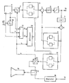
- the drawing shows as a block diagram those parts of a counter device that are required to explain the invention.
- the output signals of a video camera 1 are converted into digital video signals in an analog / digital converter 2 and temporarily stored in a first image memory 3.
- the first image memory 3 is used for temporal data reduction and, like the further image memories explained below, consists of two memories each, which are alternately written to and read out. A number of images (for example six fields) are written into one of the memories, the previous one being overwritten with one image each. Then an equal number of images are written into the other memory, while the last image written is read out from one memory, etc.
- the digital video signals read out from the first image memory 3 are fed to a DPCM loop (also called a prediction loop), which essentially consists of a subtraction circuit 4, a circuit 5 for discrete cosine transformation, a quantizer 6, a circuit 7 for inverse discrete cosine transformation, and an adder 8 and a second image memory 9, which serves as a prediction memory.
- the output signals of the quantizer 6 are fed to a receiver via an output 10, possibly after a further suitable coding, via a transmission channel (not shown).
- the receiver has a memory corresponding to the prediction memory 9, which basically contains the same content as in the prediction memory 9.
- the same signals as in the prediction memory 9 are written into a third image memory 11.
- An output of the third image memory 11 is connected via a switching device 12 and a digital / analog converter 13 to an image display device 14, which is shown in the drawing as a picture tube for the sake of simplicity.
- the switching device 12 either the signals read from the third image memory 11, representing the own image, or the signals received by an opposite station via an input 15 and the decoder of a receiver 16 can be reproduced.
- a keying of the self-image into the received image can also be provided.
- the camera 1 contains a synchronization signal generator from which synchronization signals H and V are extracted.
- a signal is supplied at a multiple of the sampling frequency f A.
- the clock signal T which is coupled to the synchronizing signal H, is generated in a PLL circuit 18.
- the clock signal T and the synchronizing signals H and V are fed to a pulse shaping circuit 17, in which signals S1 and S2 are derived, which mark the beginning of an image and a line.
- the clock signal T and the two signals S1, S2 are fed to an address generator 19 which, in a manner known per se, generates addresses for the visible image portion essentially by counting clock pulses T, taking into account the signals S1 and S2. These addresses are supplied to the first image memory 3 as write addresses and to the third image memory 11 as read addresses.
- the third image memory 11 can optionally be designed to be switchable on the input side. It can then be connected to the DPCM loop of the encoder or as a repetition memory to a device for receiving the signals of a remote station in order to display the self-image in accordance with the drawing.
Landscapes
- Engineering & Computer Science (AREA)
- Multimedia (AREA)
- Signal Processing (AREA)
- Closed-Circuit Television Systems (AREA)
- Compression Or Coding Systems Of Tv Signals (AREA)
Claims (4)
- Dispositif de vision à deux directions dans lequel les signaux vidéo produits par une caméra vidéo (1) sont susceptibles d'être mémorisés d'une façon intermédiaire dans une première mémoire d'image (3) et d'être lus avec un taux de données réduit pour la transmission par l'intermédiaire d'une boucle DPCM (4 - 9), qui comprend une seconde mémoire d'image (9), dispositif de vision à deux directions caractérisé en ce que les signaux susceptibles d'être appliqués à la seconde mémoire d'image (9) sont en outre susceptibles d'être appliqués à une troisième mémoire d'image (11) intervenant séparément de la boucle DPCM et dont la sortie, pour la représentation de l'image propre mémorisée sous la forme codée réduite en données, est reliée à un dispositif de reproduction d'image (14), et en ce que des adresses sont produites, qui représentent respectivement les positions des éléments d'image et peuvent être appliquées aussi bien à la première mémoire d'image (3) en tant qu'adresses d'inscription qu'également à la troisième mémoire d'image (11) en tant qu'adresses de lecture.
- Dispositif de vision à deux directions, selon la revendication 1, caractérisé en ce que les mémoires d'images sont chacune constituées par deux mémoires, qui sont utilisées alternativement pour l'inscription et la lecture.
- Dispositif de vision à deux directions selon la revendication 1, caractérisé en ce que la sortie de la troisième mémoire d'image (11) est reliée par l'intermédiaire d'un convertisseur numérique analogique (13) au dispositif de reproduction d'image (14).
- Dispositif de vision à deux directions, selon la revendication 3, caractérisé en ce que, entre la sortie du convertisseur numérique-analogique (13) et le dispositif de reproduction d'image (14) est prévu un dispositif de commutation (12), qui est en outre relié à la sortie des signaux du récepteur (16) pour les signaux de la contre station.
Applications Claiming Priority (2)
| Application Number | Priority Date | Filing Date | Title |
|---|---|---|---|
| DE3831643A DE3831643A1 (de) | 1988-09-17 | 1988-09-17 | Gegenseheinrichtung |
| DE3831643 | 1988-09-17 |
Publications (2)
| Publication Number | Publication Date |
|---|---|
| EP0360026A1 EP0360026A1 (fr) | 1990-03-28 |
| EP0360026B1 true EP0360026B1 (fr) | 1993-03-10 |
Family
ID=6363147
Family Applications (1)
| Application Number | Title | Priority Date | Filing Date |
|---|---|---|---|
| EP89115653A Expired - Lifetime EP0360026B1 (fr) | 1988-09-17 | 1989-08-25 | Dispositif de vision à deux directions |
Country Status (3)
| Country | Link |
|---|---|
| EP (1) | EP0360026B1 (fr) |
| DE (2) | DE3831643A1 (fr) |
| ES (1) | ES2039780T3 (fr) |
Families Citing this family (4)
| Publication number | Priority date | Publication date | Assignee | Title |
|---|---|---|---|---|
| FR2683966B1 (fr) * | 1991-11-20 | 1998-06-05 | Jacques Guichard | Procede de synchronisation du circuit de balayage d'un appareil de visualisation d'images. |
| FR2687884B1 (fr) * | 1992-02-24 | 1994-04-08 | Alcatel Cit | Codec videc, notamment visiophonique. |
| JP2503853B2 (ja) * | 1992-12-16 | 1996-06-05 | 日本電気株式会社 | 動画像復号システム |
| DE19539803A1 (de) * | 1995-10-26 | 1997-04-30 | Thomson Brandt Gmbh | Fernsehtelefonanlage |
Family Cites Families (1)
| Publication number | Priority date | Publication date | Assignee | Title |
|---|---|---|---|---|
| DE2551664C3 (de) * | 1975-11-18 | 1982-01-28 | Licentia Patent-Verwaltungs-Gmbh, 6000 Frankfurt | Kompatibles Bildfernsprechsystem |
-
1988
- 1988-09-17 DE DE3831643A patent/DE3831643A1/de not_active Withdrawn
-
1989
- 1989-08-25 ES ES198989115653T patent/ES2039780T3/es not_active Expired - Lifetime
- 1989-08-25 EP EP89115653A patent/EP0360026B1/fr not_active Expired - Lifetime
- 1989-08-25 DE DE8989115653T patent/DE58903712D1/de not_active Expired - Fee Related
Also Published As
| Publication number | Publication date |
|---|---|
| EP0360026A1 (fr) | 1990-03-28 |
| ES2039780T3 (es) | 1993-10-01 |
| DE3831643A1 (de) | 1990-03-22 |
| DE58903712D1 (de) | 1993-04-15 |
Similar Documents
| Publication | Publication Date | Title |
|---|---|---|
| DE2420830C2 (de) | Verfahren und Anordnung zur Bandbreitenkompression eines Videosignals | |
| DE3871998T2 (de) | Fernsehsystem, in dem digitalisierte transformationskodierte bildsignale von einer kodierstation zu einer dekodierstation uebertragen werden. | |
| DE3916064C2 (de) | Vorrichtung und Verfahren zum Bearbeiten eines Stehbildsignals | |
| DE3853713T2 (de) | Verfahren zur Übertragung und Anzeige eines Standbildes in einem Standbild-Videotelefon. | |
| DE3429901C2 (de) | Verfahren und anordnung zur uebertragung von daten | |
| EP0244729A1 (fr) | Procédé de transmission de valeurs MICD | |
| DE69112865T2 (de) | Verarbeitungsverfahren von digitalen Kontrolldaten, die mit einem HD-MAC-Videosignal verbunden sind. | |
| DE2617884A1 (de) | Normwandler fuer fernsehsignale | |
| DE3874478T2 (de) | Uebertragungssystem fuer bild und ton. | |
| DE3687234T2 (de) | Video-uebertragungs-systeme. | |
| EP0360026B1 (fr) | Dispositif de vision à deux directions | |
| DE69224650T2 (de) | Verfahren zur Synchronisation der Ablenkung in einem Bildwiedergabeapparat | |
| DE69230047T2 (de) | Fernsehsystem zum Übertragen von Bildsignalen in einem digitalen Format | |
| EP0298394A2 (fr) | Méthode et dispositif de réduction de la visibilité de la structure de lignes d'une image de télévision | |
| DE2808640C2 (de) | System zur Übertragung einzelner Fernsehbilder | |
| DE2551664C3 (de) | Kompatibles Bildfernsprechsystem | |
| EP0336510B1 (fr) | Codeur predictif d'image immobile | |
| EP0533675B1 (fr) | Dispositif de transmission | |
| DE3725368C2 (de) | Bildfernsprecher | |
| DE3828908A1 (de) | Bilduebertragungssystem | |
| DE69315906T2 (de) | Vorrichtung zur Videosignal-Umwandlung und Rauschunterdrückung | |
| DE69019119T2 (de) | Verfahren und Einrichtung zur Bewegtbilddecodierung. | |
| DE3901103C1 (en) | Method for transmitting stereoscopic television images | |
| DE4241006A1 (de) | Video-Überwachungsvorrichtung | |
| DE69025659T2 (de) | Standbildwiedergabevorrichtung |
Legal Events
| Date | Code | Title | Description |
|---|---|---|---|
| PUAI | Public reference made under article 153(3) epc to a published international application that has entered the european phase |
Free format text: ORIGINAL CODE: 0009012 |
|
| AK | Designated contracting states |
Kind code of ref document: A1 Designated state(s): DE ES FR GB IT |
|
| 17P | Request for examination filed |
Effective date: 19900305 |
|
| RAP3 | Party data changed (applicant data changed or rights of an application transferred) |
Owner name: ROBERT BOSCH GMBH |
|
| 17Q | First examination report despatched |
Effective date: 19920619 |
|
| GRAA | (expected) grant |
Free format text: ORIGINAL CODE: 0009210 |
|
| AK | Designated contracting states |
Kind code of ref document: B1 Designated state(s): DE ES FR GB IT |
|
| ET | Fr: translation filed | ||
| REF | Corresponds to: |
Ref document number: 58903712 Country of ref document: DE Date of ref document: 19930415 |
|
| GBT | Gb: translation of ep patent filed (gb section 77(6)(a)/1977) |
Effective date: 19930324 |
|
| ITF | It: translation for a ep patent filed | ||
| PG25 | Lapsed in a contracting state [announced via postgrant information from national office to epo] |
Ref country code: GB Effective date: 19930825 |
|
| PG25 | Lapsed in a contracting state [announced via postgrant information from national office to epo] |
Ref country code: ES Free format text: LAPSE BECAUSE OF THE APPLICANT RENOUNCES Effective date: 19930826 |
|
| REG | Reference to a national code |
Ref country code: ES Ref legal event code: FG2A Ref document number: 2039780 Country of ref document: ES Kind code of ref document: T3 |
|
| PLBE | No opposition filed within time limit |
Free format text: ORIGINAL CODE: 0009261 |
|
| STAA | Information on the status of an ep patent application or granted ep patent |
Free format text: STATUS: NO OPPOSITION FILED WITHIN TIME LIMIT |
|
| 26N | No opposition filed | ||
| GBPC | Gb: european patent ceased through non-payment of renewal fee |
Effective date: 19930825 |
|
| PG25 | Lapsed in a contracting state [announced via postgrant information from national office to epo] |
Ref country code: FR Effective date: 19940429 |
|
| PG25 | Lapsed in a contracting state [announced via postgrant information from national office to epo] |
Ref country code: DE Effective date: 19940503 |
|
| REG | Reference to a national code |
Ref country code: FR Ref legal event code: ST |
|
| REG | Reference to a national code |
Ref country code: ES Ref legal event code: FD2A Effective date: 19991007 |
|
| PG25 | Lapsed in a contracting state [announced via postgrant information from national office to epo] |
Ref country code: IT Free format text: LAPSE BECAUSE OF NON-PAYMENT OF DUE FEES;WARNING: LAPSES OF ITALIAN PATENTS WITH EFFECTIVE DATE BEFORE 2007 MAY HAVE OCCURRED AT ANY TIME BEFORE 2007. THE CORRECT EFFECTIVE DATE MAY BE DIFFERENT FROM THE ONE RECORDED. Effective date: 20050825 |