EP0360028A1 - Méthode de jonction pour conduites de chauffage - Google Patents
Méthode de jonction pour conduites de chauffage Download PDFInfo
- Publication number
- EP0360028A1 EP0360028A1 EP89115686A EP89115686A EP0360028A1 EP 0360028 A1 EP0360028 A1 EP 0360028A1 EP 89115686 A EP89115686 A EP 89115686A EP 89115686 A EP89115686 A EP 89115686A EP 0360028 A1 EP0360028 A1 EP 0360028A1
- Authority
- EP
- European Patent Office
- Prior art keywords
- foam
- bridge
- pipes
- pipe
- jacket
- Prior art date
- Legal status (The legal status is an assumption and is not a legal conclusion. Google has not performed a legal analysis and makes no representation as to the accuracy of the status listed.)
- Granted
Links
- 238000010438 heat treatment Methods 0.000 title claims abstract description 17
- 238000000034 method Methods 0.000 title claims description 5
- 239000006260 foam Substances 0.000 claims abstract description 25
- 229910000831 Steel Inorganic materials 0.000 claims abstract description 3
- 238000003780 insertion Methods 0.000 claims abstract description 3
- 230000037431 insertion Effects 0.000 claims abstract description 3
- 239000010959 steel Substances 0.000 claims abstract description 3
- 238000005187 foaming Methods 0.000 claims description 4
- 229910052751 metal Inorganic materials 0.000 claims description 2
- 239000002184 metal Substances 0.000 claims description 2
- 229910052782 aluminium Inorganic materials 0.000 abstract description 4
- XAGFODPZIPBFFR-UHFFFAOYSA-N aluminium Chemical compound [Al] XAGFODPZIPBFFR-UHFFFAOYSA-N 0.000 abstract description 4
- 239000000945 filler Substances 0.000 abstract 3
- 230000007704 transition Effects 0.000 abstract 3
- 239000004411 aluminium Substances 0.000 abstract 1
- 238000010276 construction Methods 0.000 description 2
- 239000000463 material Substances 0.000 description 1
- 238000003466 welding Methods 0.000 description 1
Images
Classifications
-
- F—MECHANICAL ENGINEERING; LIGHTING; HEATING; WEAPONS; BLASTING
- F16—ENGINEERING ELEMENTS AND UNITS; GENERAL MEASURES FOR PRODUCING AND MAINTAINING EFFECTIVE FUNCTIONING OF MACHINES OR INSTALLATIONS; THERMAL INSULATION IN GENERAL
- F16L—PIPES; JOINTS OR FITTINGS FOR PIPES; SUPPORTS FOR PIPES, CABLES OR PROTECTIVE TUBING; MEANS FOR THERMAL INSULATION IN GENERAL
- F16L59/00—Thermal insulation in general
- F16L59/14—Arrangements for the insulation of pipes or pipe systems
- F16L59/16—Arrangements specially adapted to local requirements at flanges, junctions, valves or the like
- F16L59/18—Arrangements specially adapted to local requirements at flanges, junctions, valves or the like adapted for joints
- F16L59/20—Arrangements specially adapted to local requirements at flanges, junctions, valves or the like adapted for joints for non-disconnectable joints
Definitions
- the invention relates to a method for connecting district heating pipes, which consist of a medium pipe made of steel, a jacket pipe made of plastic and a foam filling in between, the medium pipes are exposed and welded at the ends to be connected and then the gaps between the jacket pipes and the foam fillings are closed by flush insertion of a jacket pipe intermediate piece and foaming of the existing space, the intermediate piece being connected to the two adjacent jacket pipes by, in particular welded, seams and being closed at a longitudinal diameter and for which a support from the inside is provided, which is provided with is foamed.
- the intermediate piece required a complicated support from the medium pipe, which was subsequently foamed in, because otherwise the heating would cause the plastic in the vicinity of the weld seam to shrink and thus lead to a deformation of the intermediate piece; it sinks there.
- the invention has for its object to provide a simple suitable support for the intermediate piece on the longitudinal average.
- this purpose is achieved in such a way that, as the support, a bridge is placed over the gap between the foam fillings and is supported on the previously exposed, both ends of the foam fillings.
- the support of the intermediate piece is decidedly simpler and more stable, although it requires these ends to be exposed.
- the U-profile is just as simple in structure as in its attachment, in which the thinner U-legs easily cut into the foam, and this attachment is then stable and, in contrast to the known support on the carrier pipe, secure against anything Slipping, both in the axial and in the circumferential direction.
- the two ends of the adjacent foam fillings are expediently removed a little before the bridge is placed on the circumference, so that the desired alignment of the top of the bridge with the underside of the casing pipes can be set up precisely.
- the cavity that is further created by the removal under the intermediate piece is also filled when foaming.
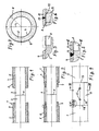
- Two district heating pipes 1 and 2 each consist of a medium pipe 3, a casing pipe 4 and a foam filling 5 between the medium pipe and casing pipe. At the ends of the district heating pipes 1 and 2, the medium pipe 3 protrudes freely so that it can be welded when the district heating pipe is laid.
- the weld seam in question is designated by 6.
- a bridge 8 is placed over the axial gap between the foam fillings 5 of the district heating pipes 1 and 2, which is still present in FIG. According to the drawing, see the difference between FIGS. 2 and 1, section 7 has been exposed at the construction site. It could also be provided at the factory, but the exposure only at the construction site has the advantage that the weaker foam is protected by the firmer jacket tube during transport and other movements of the district heating pipes.
- the bridge 8 consists, for example, of a U-section folded aluminum sheet and is so deeply pressed into the foam filling with the U-legs 9 that the top of the bridge lies flush with the outer circumference of the foam filling 5 and the inner circumference of the casing tube 4. Below this, a flat space 10 remains between the aluminum sheet and the peeled foam filling.
- the intermediate piece 11 is of the same material, same wall thick and the same diameter as the jacket tube 4, but cut parallel to the tube axis at one point on its wall.
- the longitudinal intersection 12 is welded in the same way as the joints between the intermediate piece 11 and the casing 4 of the two district heating pipes 1 and 2.
- a V-seam 13 at one of the two joints can be seen in FIG. 5, a V-seam 14 at the longitudinal intersection 12 in FIG. 7.
- the intermediate piece 11 is supported by the bridge 8 from the inside when welding the longitudinal average 12 to it.
- the cavity under the intermediate piece 11 is then foamed through a hole or a plurality of holes 15 in the intermediate piece 11 in a manner known per se.
- the bridge 8 is also foamed. 4, 5 and 7 show the stage after foaming. In Fig. 6 the intermediate piece is inserted, but not yet foamed.
Landscapes
- Engineering & Computer Science (AREA)
- General Engineering & Computer Science (AREA)
- Mechanical Engineering (AREA)
- Lining Or Joining Of Plastics Or The Like (AREA)
Priority Applications (1)
| Application Number | Priority Date | Filing Date | Title |
|---|---|---|---|
| AT89115686T ATE76682T1 (de) | 1988-09-17 | 1989-08-25 | Verfahren zum verbinden von fernwaermeleitungsrohren. |
Applications Claiming Priority (2)
| Application Number | Priority Date | Filing Date | Title |
|---|---|---|---|
| DE3831623A DE3831623A1 (de) | 1988-09-17 | 1988-09-17 | Verfahren zum verbinden von fernwaermeleitungsrohren |
| DE3831623 | 1988-09-17 |
Publications (2)
| Publication Number | Publication Date |
|---|---|
| EP0360028A1 true EP0360028A1 (fr) | 1990-03-28 |
| EP0360028B1 EP0360028B1 (fr) | 1992-05-27 |
Family
ID=6363137
Family Applications (1)
| Application Number | Title | Priority Date | Filing Date |
|---|---|---|---|
| EP89115686A Expired - Lifetime EP0360028B1 (fr) | 1988-09-17 | 1989-08-25 | Méthode de jonction pour conduites de chauffage |
Country Status (3)
| Country | Link |
|---|---|
| EP (1) | EP0360028B1 (fr) |
| AT (1) | ATE76682T1 (fr) |
| DE (2) | DE3831623A1 (fr) |
Cited By (6)
| Publication number | Priority date | Publication date | Assignee | Title |
|---|---|---|---|---|
| WO1994029635A1 (fr) * | 1993-06-15 | 1994-12-22 | Abb District Heating Technology A/S | Pose de conduites de chauffage urbain et procede pour effectuer cette extension |
| WO1998001697A1 (fr) * | 1996-07-03 | 1998-01-15 | Bredero Price Coaters Limited | Raccord |
| RU2178859C2 (ru) * | 2000-12-08 | 2002-01-27 | Закрытое акционерное общество МосФлоулайн | Теплоизолированный стык предварительно теплоизолированных трубопроводов, способ его выполнения и способ ремонта трубопроводов |
| WO2013110947A1 (fr) * | 2012-01-25 | 2013-08-01 | Subsea 7 Limited | Raccords de structures sous-marines de type conduite dans conduite |
| RU2699152C2 (ru) * | 2017-07-11 | 2019-09-03 | Общество с ограниченной ответственностью "СТЕКЛОНиТ Менеджмент" | Система изоляции в трассовых условиях монтажных стыков смежных трубопроводов с изоляционным покрытием |
| CN113210917A (zh) * | 2021-05-19 | 2021-08-06 | 江苏安全技术职业学院 | 一种滚筒式自动焊接机 |
Citations (3)
| Publication number | Priority date | Publication date | Assignee | Title |
|---|---|---|---|---|
| EP0098024A1 (fr) * | 1982-06-29 | 1984-01-11 | i.c. Möller a/s | Procédé de raccordement de tuyaux préfabriqués et isolés à la chaleur et raccord de soudure pour celui-ci |
| FR2535570A1 (fr) * | 1982-10-29 | 1984-05-04 | Kabelmetal Electro Gmbh | Bande a chauffage electrique pour la realisation d'une jonction par manchon pour canalisation tubulaire thermiquement isolee, et son procede de fabrication |
| EP0278050A1 (fr) * | 1987-01-30 | 1988-08-17 | kabelmetal electro GmbH | Raccord à manchon pour tuyaux isolés thermiquement |
-
1988
- 1988-09-17 DE DE3831623A patent/DE3831623A1/de not_active Withdrawn
-
1989
- 1989-08-25 EP EP89115686A patent/EP0360028B1/fr not_active Expired - Lifetime
- 1989-08-25 AT AT89115686T patent/ATE76682T1/de not_active IP Right Cessation
- 1989-08-25 DE DE8989115686T patent/DE58901535D1/de not_active Expired - Lifetime
Patent Citations (3)
| Publication number | Priority date | Publication date | Assignee | Title |
|---|---|---|---|---|
| EP0098024A1 (fr) * | 1982-06-29 | 1984-01-11 | i.c. Möller a/s | Procédé de raccordement de tuyaux préfabriqués et isolés à la chaleur et raccord de soudure pour celui-ci |
| FR2535570A1 (fr) * | 1982-10-29 | 1984-05-04 | Kabelmetal Electro Gmbh | Bande a chauffage electrique pour la realisation d'une jonction par manchon pour canalisation tubulaire thermiquement isolee, et son procede de fabrication |
| EP0278050A1 (fr) * | 1987-01-30 | 1988-08-17 | kabelmetal electro GmbH | Raccord à manchon pour tuyaux isolés thermiquement |
Cited By (11)
| Publication number | Priority date | Publication date | Assignee | Title |
|---|---|---|---|---|
| WO1994029635A1 (fr) * | 1993-06-15 | 1994-12-22 | Abb District Heating Technology A/S | Pose de conduites de chauffage urbain et procede pour effectuer cette extension |
| GB2294742A (en) * | 1993-06-15 | 1996-05-08 | Abb District Heating Managemen | A district heating pipe stretch and a method of establishing such a stretch |
| WO1998001697A1 (fr) * | 1996-07-03 | 1998-01-15 | Bredero Price Coaters Limited | Raccord |
| US6264871B1 (en) | 1996-07-03 | 2001-07-24 | Bredero Price Coaters Ltd. | Field joint |
| RU2178859C2 (ru) * | 2000-12-08 | 2002-01-27 | Закрытое акционерное общество МосФлоулайн | Теплоизолированный стык предварительно теплоизолированных трубопроводов, способ его выполнения и способ ремонта трубопроводов |
| WO2013110947A1 (fr) * | 2012-01-25 | 2013-08-01 | Subsea 7 Limited | Raccords de structures sous-marines de type conduite dans conduite |
| GB2498740B (en) * | 2012-01-25 | 2014-09-10 | Subsea 7 Ltd | Connections for subsea pipe-in-pipe structures |
| US9857011B2 (en) | 2012-01-25 | 2018-01-02 | Subsea 7 Limited | Connections for subsea pipe-in-pipe structures |
| RU2699152C2 (ru) * | 2017-07-11 | 2019-09-03 | Общество с ограниченной ответственностью "СТЕКЛОНиТ Менеджмент" | Система изоляции в трассовых условиях монтажных стыков смежных трубопроводов с изоляционным покрытием |
| CN113210917A (zh) * | 2021-05-19 | 2021-08-06 | 江苏安全技术职业学院 | 一种滚筒式自动焊接机 |
| CN113210917B (zh) * | 2021-05-19 | 2022-11-25 | 江苏安全技术职业学院 | 一种滚筒式自动焊接机 |
Also Published As
| Publication number | Publication date |
|---|---|
| DE58901535D1 (de) | 1992-07-02 |
| ATE76682T1 (de) | 1992-06-15 |
| EP0360028B1 (fr) | 1992-05-27 |
| DE3831623A1 (de) | 1990-03-22 |
Similar Documents
| Publication | Publication Date | Title |
|---|---|---|
| DE2635126C3 (de) | Druckmittelbetätigte Halteeinrichtung | |
| DE2219196A1 (de) | Rohrkupplung | |
| DE3509217C2 (de) | Verfahren zum Verbinden einer Hülse mit einem Rohr einer Unterwasserrohrleitung | |
| DE3427945C2 (fr) | ||
| EP0521822B1 (fr) | Dispositif pour le raccordement de deux gaines | |
| DE3744510A1 (de) | Rohrverbindungs-element | |
| DE69319421T2 (de) | Verfahren zum bohren von deckgebirge, verrohrungsschuh und verrohrung für diese methode und kupplungselemente für die verrohrung | |
| DE2015341A1 (de) | Rohrverbindung und Verfahren zu ihrer Herstellung | |
| DE8234897U1 (de) | Leitungsrohr fuer eine kanalgrundrohrleitung | |
| EP0360028A1 (fr) | Méthode de jonction pour conduites de chauffage | |
| DE2002826A1 (de) | Kupplungsstueck fuer Roehren oder Schlaeuche | |
| DE3315819A1 (de) | Rohrleitung (pipeline) zur foerderung von insbesondere aggresiven medien und verfahren zum zusammensetzen bzw. verlegen der rohrleitung | |
| DE2646359B2 (de) | Rohrkupplung zum zugfesten MHeinanderverbinden von Rohrenden | |
| DE2362926A1 (de) | Verfahren zum verbinden von rohren sowie rohrmuffe zur durchfuehrung des verfahrens | |
| DE3826078A1 (de) | Verfahren zum verbinden von fernwaermeleitungsrohren | |
| DE2016440C3 (de) | Rohrverbindung | |
| DE3534174A1 (de) | Krumpfmuffe aus kunststoff zum verbinden von zwei rohrenden | |
| CH690990A5 (de) | Verfahren, Heizmatte und Manschette zum Verbinden von Kunststoffrohren. | |
| DE2352711C3 (de) | Einspannvorrichtung für ein schlauchförmiges elastisches Kupplungsstück | |
| DE20201874U1 (de) | Vorrichtung zur dichten Verbindung eines Wellschlauches mit einem Gegenstück | |
| DE3512501C2 (de) | Verfahren und Vorrichtung zur Herstellung eines doppelwandigen Rohrs für den Feststofftransport | |
| CH688355A5 (de) | Verfahren zur Verhinderung der raschen Rissausbreitung bei Kunststoffrohren und nach dem Verfahren hergestellte Kunststoffrohre. | |
| DE1525677C (de) | Rohrmuffe zum gegenseitigen Verbinden zweier Rohre | |
| DE8807095U1 (de) | Bausatz zum Aufbau eines Doppelrohr-Leitungssystems | |
| DE8428374U1 (de) | Kunststoffrohr zum sanieren von rohrleitungen |
Legal Events
| Date | Code | Title | Description |
|---|---|---|---|
| PUAI | Public reference made under article 153(3) epc to a published international application that has entered the european phase |
Free format text: ORIGINAL CODE: 0009012 |
|
| AK | Designated contracting states |
Kind code of ref document: A1 Designated state(s): AT BE CH DE FR IT LI NL |
|
| 17P | Request for examination filed |
Effective date: 19900816 |
|
| 17Q | First examination report despatched |
Effective date: 19910328 |
|
| GRAA | (expected) grant |
Free format text: ORIGINAL CODE: 0009210 |
|
| AK | Designated contracting states |
Kind code of ref document: B1 Designated state(s): AT BE CH DE FR IT LI NL |
|
| REF | Corresponds to: |
Ref document number: 76682 Country of ref document: AT Date of ref document: 19920615 Kind code of ref document: T |
|
| ITF | It: translation for a ep patent filed | ||
| REF | Corresponds to: |
Ref document number: 58901535 Country of ref document: DE Date of ref document: 19920702 |
|
| ET | Fr: translation filed | ||
| PLBE | No opposition filed within time limit |
Free format text: ORIGINAL CODE: 0009261 |
|
| STAA | Information on the status of an ep patent application or granted ep patent |
Free format text: STATUS: NO OPPOSITION FILED WITHIN TIME LIMIT |
|
| 26N | No opposition filed | ||
| PGFP | Annual fee paid to national office [announced via postgrant information from national office to epo] |
Ref country code: FR Payment date: 19940620 Year of fee payment: 6 |
|
| PGFP | Annual fee paid to national office [announced via postgrant information from national office to epo] |
Ref country code: CH Payment date: 19940728 Year of fee payment: 6 |
|
| PGFP | Annual fee paid to national office [announced via postgrant information from national office to epo] |
Ref country code: AT Payment date: 19940823 Year of fee payment: 6 |
|
| PGFP | Annual fee paid to national office [announced via postgrant information from national office to epo] |
Ref country code: BE Payment date: 19940902 Year of fee payment: 6 |
|
| PG25 | Lapsed in a contracting state [announced via postgrant information from national office to epo] |
Ref country code: AT Effective date: 19950825 |
|
| PG25 | Lapsed in a contracting state [announced via postgrant information from national office to epo] |
Ref country code: LI Effective date: 19950831 Ref country code: CH Effective date: 19950831 Ref country code: BE Effective date: 19950831 |
|
| BERE | Be: lapsed |
Owner name: DSD - DILLINGER STAHLBAU G.M.B.H. Effective date: 19950831 |
|
| REG | Reference to a national code |
Ref country code: CH Ref legal event code: PL |
|
| PG25 | Lapsed in a contracting state [announced via postgrant information from national office to epo] |
Ref country code: FR Effective date: 19960430 |
|
| REG | Reference to a national code |
Ref country code: FR Ref legal event code: ST |
|
| PGFP | Annual fee paid to national office [announced via postgrant information from national office to epo] |
Ref country code: NL Payment date: 19990823 Year of fee payment: 11 |
|
| PG25 | Lapsed in a contracting state [announced via postgrant information from national office to epo] |
Ref country code: NL Free format text: LAPSE BECAUSE OF NON-PAYMENT OF DUE FEES Effective date: 20010301 |
|
| NLV4 | Nl: lapsed or anulled due to non-payment of the annual fee |
Effective date: 20010301 |
|
| PG25 | Lapsed in a contracting state [announced via postgrant information from national office to epo] |
Ref country code: IT Free format text: LAPSE BECAUSE OF NON-PAYMENT OF DUE FEES;WARNING: LAPSES OF ITALIAN PATENTS WITH EFFECTIVE DATE BEFORE 2007 MAY HAVE OCCURRED AT ANY TIME BEFORE 2007. THE CORRECT EFFECTIVE DATE MAY BE DIFFERENT FROM THE ONE RECORDED. Effective date: 20050825 |
|
| PGFP | Annual fee paid to national office [announced via postgrant information from national office to epo] |
Ref country code: DE Payment date: 20060818 Year of fee payment: 18 |
|
| PG25 | Lapsed in a contracting state [announced via postgrant information from national office to epo] |
Ref country code: DE Free format text: LAPSE BECAUSE OF NON-PAYMENT OF DUE FEES Effective date: 20080301 |