EP0360057A2 - Maschinenkühlmittel-Spülfilterunganlage und Verfahren - Google Patents
Maschinenkühlmittel-Spülfilterunganlage und Verfahren Download PDFInfo
- Publication number
- EP0360057A2 EP0360057A2 EP89116208A EP89116208A EP0360057A2 EP 0360057 A2 EP0360057 A2 EP 0360057A2 EP 89116208 A EP89116208 A EP 89116208A EP 89116208 A EP89116208 A EP 89116208A EP 0360057 A2 EP0360057 A2 EP 0360057A2
- Authority
- EP
- European Patent Office
- Prior art keywords
- coolant
- cooling system
- radiator
- coolant liquid
- opening
- Prior art date
- Legal status (The legal status is an assumption and is not a legal conclusion. Google has not performed a legal analysis and makes no representation as to the accuracy of the status listed.)
- Ceased
Links
Images


Classifications
-
- F—MECHANICAL ENGINEERING; LIGHTING; HEATING; WEAPONS; BLASTING
- F01—MACHINES OR ENGINES IN GENERAL; ENGINE PLANTS IN GENERAL; STEAM ENGINES
- F01P—COOLING OF MACHINES OR ENGINES IN GENERAL; COOLING OF INTERNAL-COMBUSTION ENGINES
- F01P11/00—Component parts, details, or accessories not provided for in, or of interest apart from, groups F01P1/00 - F01P9/00
- F01P11/06—Cleaning; Combating corrosion
-
- F—MECHANICAL ENGINEERING; LIGHTING; HEATING; WEAPONS; BLASTING
- F01—MACHINES OR ENGINES IN GENERAL; ENGINE PLANTS IN GENERAL; STEAM ENGINES
- F01P—COOLING OF MACHINES OR ENGINES IN GENERAL; COOLING OF INTERNAL-COMBUSTION ENGINES
- F01P11/00—Component parts, details, or accessories not provided for in, or of interest apart from, groups F01P1/00 - F01P9/00
- F01P11/06—Cleaning; Combating corrosion
- F01P2011/065—Flushing
Definitions
- This invention relates generally to cleaning of an internal combustion engine cooling system, and more particularly to treatment of used coolant exteriorly of such a system for subsequent return to the system.
- the invention may provide procedures and apparatus for overcoming the problems and meeting the needs set forth above, whereby rapid and efficient cleaning of the engine coolant system may be accomplished in an environmentally non-objectionable manner.
- the method of the invention may embody the following steps:
- An alternative to e) above comprises the cooling system including a container having a coolant liquid fill opening, and a valve controlled discharge port proximate the bottom of the radiator, the forcing step employing the gas to drive coolant liquid from the radiator via the discharge port.
- the invention may provide for the supply of a pressurized gas such as air to the cooling system in such a way as to drive coolant therefrom, for external treatment as in a holding tank zone.
- a pressurized gas such as air
- the invention may also provide a siphoning probe insertible into the radiator associated with the engine to provide a path for coolant to exit the radiator from its lower interior, for external treatment.
- the probe is associated with a closure for the radiator fill port, to keep that port closed during performance of the steps a) - f) referred to above, preventing ejection of hot fluid which could harm the operator.
- the invention may further provide a path for pressurized coolant to exit the radiator from its lower interior, for external treatment, while a radiator fill port is maintained closed to prevent injury to the user, which could occur by hot fluid discharge from the radiator interior, via an open fill port.
- Additional steps may include filtering contaminant particulate from the coolant as it flows to the external treatment zone; adding fresh chemicals to the radiator after completion of service; employing gas pressure to drive the coolant from the holding zone back to the coolant system at the engine, and filtering the returning coolant. Further, the driving gas pressure may be employed to test the coolant system for any leakage.
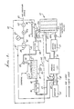
- Fig. 1 there is schematically shown an internal combustion engine 10 having a block 11 defining coolant passages through which liquid coolant (such as water, and anti-freeze additive including polyethylene glycol, etc.) is adapted to pass.
- the engine 10 includes a radiator 12, and a coolant pump 13 connected to pump coolant between the block and radiator, via lines or ducts 14 and 14 a .
- a heater 15 connected at 17 with the block, for use in a vehicle to be heated. From the heater, coolant may pass at 18 to the engine block 11.
- the coolant tends to become contaminated with particulate such as rust particles and precipitate (calcium salts, etc.), and the additive degenerates.
- the coolant was drained from the system to sewer lines, and the system flushed with liquid which was also drained.
- the present invention preferably eliminates such environmentally objectionable draining, and also protects the operator.
- apparatus generally designated at 20 is provided, and comprises:
- the method and apparatus of the invention make possible the re-use of the coolant by withdrawing it from the coolant system, treating it externally of that system, and re-circulating the rejuvenated coolant back into the system so as to avoid disposal of the coolant by drainage to the environment.
- the first means for forcing the liquid coolant from the coolant system may advantageously include an elongated tube or tubular probe 21 insertible endwise into the outer container or shell 22 of the radiator, and via the usual fill opening 23 a of that shell to extract coolant from the lower interior of the radiator for passage from the radiator via duct 23.
- Means 24 associated with, and typically carried by, that tubular probe 21, is provided for maintaining the fill opening otherwise closed during removal of coolant from the radiator.
- Such means may comprise a screw-on cap 24 which is annular to pass the elongated tube 21. The cap is screwed onto the neck 25 of the radiator fill-opening so that the probe then reaches near the bottom interior of the radiator so that substantially all liquid may be removed, extracted or siphoned from the radiator, to the line 23. Liquid in the heater and block flows to the radiator for such removal, and typically under pressure within the radiator so as to flow up the tubular probe to the external line 23 and then to a treatment zone.
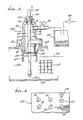
- Figs. 2 and 5 show cap details.
- the second means for treating the removed coolant may advantageously comprise a liquid receiver in the form of a holding tank 27 to which liquid flows via line 23, a filter 28 connected in series with that line, and valve 29 in the line. Particulate and congealed substances in the flowing liquid are removed by the filter 28, which may be replaced at intervals.
- the used-up filter is disposed of in accordance with environmentally acceptably safe procedures.
- the normally aqueous liquid received into the holding tank interior zone 31, via inlet 30, may then be treated by addition of a chemical agent or agents introduced via port 32.
- Such chemicals may include corrosion inhibitor i.e. anti-rust compound, pH adjustment chemicals, and fresh anti-freeze compound (for example, glycol). Such chemicals may also be added to the radiator, after return of treated coolant thereto. If any sludge develops in tank 27 after prolonged use, it may be removed to a container 34 and disposed of in an environmentally safe manner. See line 35 and valve 36.
- the third means for returning the treated coolant to the engine cooling system includes a line or duct 37 extending from the tank 27 to a connection 38 with the cooling system.
- the connection 38 is advantageously located in the line 17 from the block 11 to the heater.
- a clamp 39 may be located on or at that line for stopping liquid passing from connection 38 to the block, via line 17.
- a control valve 40 and a filter 41 are connected in series in line 37, the valve 40 being opened when return of coolant to the system is desired.
- the filter 41 removes any further contaminant.
- An important feature of the invention is the provision, in association with the first means referred to above, of a pressurized gas (for example, air) source 43 connectible via a main valve 44 in a duct 45 to a control valve 46.
- the control valve 46 is connected via line 47 with the coolant system and forces coolant from that system to the tank 27 via the probe 21 and/or line 23.
- the line 47 may be connected to duct 17, at 48, as shown.
- Air pressure drives coolant from the heater to the radiator, via line 18 and the pump 13. Coolant also flows from the block 11 to the radiator lower interior extent 12 a , for removal by the probe 21.
- the valve 46 is a three-way valve, and is controllable to alternatively supply air under pressure via line 52 to the holding tank interior for application to treated liquid in the tank, and for return under pressure to the engine cooling system, along the flow path described above.
- the engine Prior to initial operation of the system, the engine is operated to heat the coolant in the system, and as a result a thermostat controlled valve in that system, indicated at 60, is opened when the coolant reaches a predetermined temperature. Rust loosening or cleaning chemical additive (such as detergent solution) may be initially added to the coolant in the radiator to circulate during warm-up. The probe 21 is then inserted in the radiator, and operation of the apparatus is begun. Note that the apparatus is quickly connectible to the cooling system, via hoses or lines 23, 37 and 47.
- Rust loosening or cleaning chemical additive such as detergent solution
- a pressure gauge 63 is connected to air line 45 to indicate the pressure in that line.
- the radiator fill opening 23 a is closed by returning the radiator cap to the neck 25, and tightening it to seal the opening 23 a .
- air pressure from supply 43 pressurizes the entire coolant system, and the gauge 63 is observed to note the pressure.
- An air pressure regulator 45 a in the line 45 regulates the pressure to a safe level.
- the valve 44 is then closed, and the gauge 63 is again observed to note any relatively rapid fall-off in pressure. If that does not occur, the pressure test indicates a non-leaking system. If the pressure falls-off, the test indicates that a leak has developed in the coolant system, and should be attended to. For example, a STOP-LEAK solution may be added to the contents of the radiator in an effort to arrest the pressure leak.
- the modified cap 24 a has a domed wall 90 with a central opening 91 to accommodate the tubular probe 21.
- a seal 92 carried by the cap seals off against the outer surface of the probe (which may be plastic) when a threaded fitting 150 is tightened in a threaded bore 151.
- the probe is axially shiftable, endwise, relative to the opening 91, when the fitting 150 is loosened.
- the cap has a lower lip 93 that tightens on the annular lip 94 of the radiator container, as shown, at which time an annular extension 152 fits in a radiator bore 153, sealing at 154.
- An off-set through a port 95 has a by-pass duct 96 connected therewith at 97, and a manually controllable by-pass valve 98 in the duct 96 controls escape of pressurized fluid from the radiator upper interior 12 b , to an over-flow tank 100.
- a by-pass valve 98 is opened during air pressure induced return of treated coolant fluid to the system. Fluid is allowed to rise in the radiator, to level 101, above the indicator core 104. Any excess fluid (air, coolant or both) rising in the radiator exits via the by-pass duct and the valve 98, to the tank 100.
- the duct 96 is transparent so that any loss of coolant can be visually monitored. Coolant collected in the tank 100 can be returned to the tank 27 by siphoning, through a siphon 106.
- the radiator container or shell appears at 109.
- the first means for forcing the liquid coolant from the coolant system may advantageously include a coolant discharge port 110 at the bottom of the radiator, in series with a valve 111, manually controlled at control 112. Air pressurized coolant is forced from the lower interior or extent of the radiator, through the duct 123, to the tank 27.
- Means 24 is provided for maintaining the usual radiator fill opening 23 a otherwise closed during removal of coolant from the radiator.
- Such means may comprise a screw-on cap 24 a which is located above the upper interior 12 b of the radiator and the finned tubes 104.
- a cap 24 a is screwed onto the neck of the radiator fill-opening at screw connection 93, 94.
- a valve 111 at the bottom wall 109 of the radiator container communicates with the bottom interior 12 a of the container so that substantially all pressurized coolant liquid may be removed, extracted or drained from the radiator, to the line 123. Liquid in the heater and engine block flows to the radiator for such removal.
- a modified cap 24 a for the fill port 23 a has a domed wall 90 with a central opening 91 usable to induce a vacuum at the upper interior 12 b of the radiator. See the siphon bulb 294 in series with the bypass valve 98 in Fig. 4.
- a seal 92 carried by the cap seals off when a threaded fitting 152 is tightened in a threaded bore 151, to close the cap 24 a .
- the cap has a lower lip 93 that tightens on the annular lip 94 of the radiator container, as shown, at which time an annular extension 149 fits in the radiator bore 153, sealing at 154.
- An offset through port 95 in the wall 90 has a by-pass duct 96 connected therewith, at 97, and a manually controllable by-pass valve 98 in the duct 96 controls the escape of pressurized fluid from the radiator upper interior 12 b to an over-flow tank 100.
- the valve 98 is opened, during air pressurized and induced return of treated coolant fluid to the system, so that fluid is normally allowed to rise in the radiator to the level 101 above the radiator core 104. Any excess fluid (air, coolant or both) rising in the radiator exits via the by-pass duct and valve 98 to the tank 100.
- radiator fill port 23 a is closed by the cap 24 a , with a fitting 152 installed in a bore 151.
- the by-pass valve 98 is also used with a siphon-vacuum bulb 294 to induce a vacuum at 12 b , when original equipment is removed from the bottom of the radiator and a special coolant discharge port or duct 110 is installed into the bottom of the radiator at 109, in series with the valve 111.
- Coolant collected in the tank 100 can be siphoned out and returned to the tank 27, by a siphon which includes a hose 107 and a bulb 106,
- the radiator shell or container 109 contains the core 104.
- the first means for forcing the liquid coolant from the coolant system may advantageously include an elongated tube or tubular probe 21 insertible endwise into the outer container or shell 22 incorporated by the radiator, and via the port 151 in the cap 24 a , to extract coolant from the lower interior or extent of the radiator, for passage from the radiator as via return duct 23.
- connections to line 17 may take the form of those described in U.S. Patent 4,109,703, Fig. 12.
- Fig. 3 shows valve controls on a console panel 105, along with the gauge 63.
- a flow indicator (spinner) connected into line 17, is shown at 106.
Landscapes
- Engineering & Computer Science (AREA)
- Chemical & Material Sciences (AREA)
- Combustion & Propulsion (AREA)
- Mechanical Engineering (AREA)
- General Engineering & Computer Science (AREA)
- Cleaning By Liquid Or Steam (AREA)
- Filtration Of Liquid (AREA)
Applications Claiming Priority (4)
| Application Number | Priority Date | Filing Date | Title |
|---|---|---|---|
| US248172 | 1981-03-30 | ||
| US07/248,172 US4899807A (en) | 1987-08-20 | 1988-09-23 | Engine coolant flush-filtering using external gas pressure and blocked radiator fill port |
| US256328 | 1988-10-03 | ||
| US07/256,328 US4901786A (en) | 1987-08-20 | 1988-10-03 | Engine coolant flush-filtering using external gas pressure and radiator valving |
Publications (2)
| Publication Number | Publication Date |
|---|---|
| EP0360057A2 true EP0360057A2 (de) | 1990-03-28 |
| EP0360057A3 EP0360057A3 (de) | 1990-07-18 |
Family
ID=26939153
Family Applications (1)
| Application Number | Title | Priority Date | Filing Date |
|---|---|---|---|
| EP89116208A Ceased EP0360057A3 (de) | 1988-09-23 | 1989-09-01 | Maschinenkühlmittel-Spülfilterunganlage und Verfahren |
Country Status (5)
| Country | Link |
|---|---|
| EP (1) | EP0360057A3 (de) |
| JP (1) | JPH02185616A (de) |
| AU (1) | AU626217B2 (de) |
| MX (1) | MX164369B (de) |
| NZ (1) | NZ230618A (de) |
Family Cites Families (8)
| Publication number | Priority date | Publication date | Assignee | Title |
|---|---|---|---|---|
| US3094131A (en) * | 1961-04-11 | 1963-06-18 | Henry L Williams | Vehicle cooling system cleaning apparatus |
| US4161979A (en) * | 1977-04-25 | 1979-07-24 | Stearns Earl J | Method of and apparatus for flushing an automobile cooling system |
| JPS6059481B2 (ja) * | 1979-12-08 | 1985-12-25 | 富士電機株式会社 | 火力・原子力発電プラントにおける給水系統の濾過装置 |
| US4336133A (en) * | 1980-11-25 | 1982-06-22 | Johnson Robert C | Ethylene glycol antifreeze repurification apparatus |
| US4343353A (en) * | 1980-11-26 | 1982-08-10 | John Tsopelas | Automobile radiator filter |
| JPS59170422A (ja) * | 1983-03-18 | 1984-09-26 | Yamaha Motor Co Ltd | 船舶用水冷エンジンにおける冷却水の濾過装置 |
| US4597416A (en) * | 1984-09-19 | 1986-07-01 | Scales Frank J | Automotive air conditioning system flushing apparatus |
| US4793403A (en) * | 1987-08-20 | 1988-12-27 | Wynn Oil Company | Engine coolant flush-filtering, using external gas pressure |
-
1989
- 1989-09-01 EP EP89116208A patent/EP0360057A3/de not_active Ceased
- 1989-09-12 NZ NZ23061889A patent/NZ230618A/en unknown
- 1989-09-19 MX MX1759089A patent/MX164369B/es unknown
- 1989-09-21 AU AU41716/89A patent/AU626217B2/en not_active Ceased
- 1989-09-22 JP JP24784789A patent/JPH02185616A/ja active Pending
Also Published As
| Publication number | Publication date |
|---|---|
| AU4171689A (en) | 1990-03-29 |
| NZ230618A (en) | 1992-07-28 |
| EP0360057A3 (de) | 1990-07-18 |
| MX164369B (es) | 1992-08-06 |
| JPH02185616A (ja) | 1990-07-20 |
| AU626217B2 (en) | 1992-07-23 |
Similar Documents
| Publication | Publication Date | Title |
|---|---|---|
| US4793403A (en) | Engine coolant flush-filtering, using external gas pressure | |
| US4901786A (en) | Engine coolant flush-filtering using external gas pressure and radiator valving | |
| US4899807A (en) | Engine coolant flush-filtering using external gas pressure and blocked radiator fill port | |
| EP0382255B1 (de) | Maschinenkühlmittel-Spülfilterung ausserhalb einer Maschine mit Ionenausfällung | |
| US4809769A (en) | Engine coolant flush-filtering using external gas pressure | |
| US5078866A (en) | Engine coolant flush-filtering externally of engine with ion precipitation | |
| US4109703A (en) | Engine cooling system flushing apparatus and method | |
| US5242273A (en) | Method and apparatus for internal combustion engine coolant extractor/injector | |
| US4293031A (en) | Engine cooling system flushing apparatus and method | |
| US5094757A (en) | Radiator cooling system cleaner/refiner | |
| CA1301027C (en) | Power back scrubbing and flushing system for cooling systems | |
| US5103878A (en) | Appartaus and method for flushing and draining the coolant system of a vehicle | |
| US4209063A (en) | Engine cooling system flushing apparatus and method | |
| US5306430A (en) | Engine coolant pressure relief method and apparatus | |
| US5337774A (en) | Marine engine maintenance | |
| US3188006A (en) | Apparatus for cleaning and filling engine cooling systems | |
| AU626217B2 (en) | Engine coolant flush-filtering using external gas pressure and blocked radiator fill port | |
| USRE31274E (en) | Engine cooling system flushing apparatus and method | |
| US3834355A (en) | Steam systems equipped with an exchange reservoir | |
| US5267606A (en) | Vehicular flushing and draining apparatus and method | |
| US5441101A (en) | Recycling machine | |
| US4614226A (en) | Vehicle heater repair apparatus and method | |
| JPH0625661Y2 (ja) | 燃料油前処理装置のドレン抜き及び空気・ガス抜き装置 | |
| US2650602A (en) | Cleaner for engine cooling systems | |
| KR100551846B1 (ko) | 차량 히팅시스템의 기포 제거장치 |
Legal Events
| Date | Code | Title | Description |
|---|---|---|---|
| PUAI | Public reference made under article 153(3) epc to a published international application that has entered the european phase |
Free format text: ORIGINAL CODE: 0009012 |
|
| AK | Designated contracting states |
Kind code of ref document: A2 Designated state(s): AT BE CH DE ES FR GB GR IT LI LU NL SE |
|
| PUAL | Search report despatched |
Free format text: ORIGINAL CODE: 0009013 |
|
| AK | Designated contracting states |
Kind code of ref document: A3 Designated state(s): AT BE CH DE ES FR GB GR IT LI LU NL SE |
|
| 17P | Request for examination filed |
Effective date: 19901204 |
|
| 17Q | First examination report despatched |
Effective date: 19910305 |
|
| STAA | Information on the status of an ep patent application or granted ep patent |
Free format text: STATUS: THE APPLICATION HAS BEEN REFUSED |
|
| 18R | Application refused |
Effective date: 19930710 |