EP0360089A2 - Connexion à fiches - Google Patents
Connexion à fiches Download PDFInfo
- Publication number
- EP0360089A2 EP0360089A2 EP89116599A EP89116599A EP0360089A2 EP 0360089 A2 EP0360089 A2 EP 0360089A2 EP 89116599 A EP89116599 A EP 89116599A EP 89116599 A EP89116599 A EP 89116599A EP 0360089 A2 EP0360089 A2 EP 0360089A2
- Authority
- EP
- European Patent Office
- Prior art keywords
- plug
- connections
- shells
- connection
- connector according
- Prior art date
- Legal status (The legal status is an assumption and is not a legal conclusion. Google has not performed a legal analysis and makes no representation as to the accuracy of the status listed.)
- Withdrawn
Links
Images

Classifications
-
- H—ELECTRICITY
- H01—ELECTRIC ELEMENTS
- H01R—ELECTRICALLY-CONDUCTIVE CONNECTIONS; STRUCTURAL ASSOCIATIONS OF A PLURALITY OF MUTUALLY-INSULATED ELECTRICAL CONNECTING ELEMENTS; COUPLING DEVICES; CURRENT COLLECTORS
- H01R13/00—Details of coupling devices of the kinds covered by groups H01R12/70 or H01R24/00 - H01R33/00
- H01R13/40—Securing contact members in or to a base or case; Insulating of contact members
- H01R13/42—Securing in a demountable manner
- H01R13/424—Securing in base or case composed of a plurality of insulating parts having at least one resilient insulating part
Definitions
- the invention relates to a connector, in particular for the wiring of boiler controls with peripheral devices according to the preamble of the main claim.
- frost control function time switch with daily and weekly program, as well as separate switching times for boiler and process water preparation are integrated in the control system
- the invention is therefore based on the object to provide a plug or connection connection which, despite its simple construction, enables all-round encapsulation of all current-carrying parts when separated into a low-voltage and a normal-voltage range with nevertheless easy accessibility, with the proviso that the cable connections to be able to minimize between the plug connection and regulating and control devices, to create compatibility with all available regulations and, furthermore, to ensure easy interchangeability when the plug-in connections are securely connected.
- a plug connection is created which, with a simple training, fulfills the overall requirements.
- the two side push-on shells ensure that all current-carrying parts are enclosed on all sides, and the middle section ensures a consistent separation between the low-voltage and normal-voltage ranges. Since the plug-in receptacles and plug-in connections and also the plug-in connection latches are provided with corresponding grid dimensions, their interchangeability within the plug connection is also guaranteed.
- the push-on shells have open spaces in addition to the plug-in receptacle recesses, which of course correspond to a multiple of the grid dimension in their length, ie the shells are not simply open at the bottom, the possibility is created in further training for a plug-in connection of the plug-in connections, which will be explained in more detail.
- the plug connections at the bottom of the shell recesses protrude, these are, and this is essential, arranged in the lower area of the interior of the shells at the connection latches there, which means that there is sufficient space inside the shells to on the one hand wire the receptacle connections to one another and also to accommodate the large number of individual cable harnesses on the other A maximum of four multi-core connecting cables coming out of the plug connection upwards belong to the control device.
- the aforementioned free areas of the shells next to their recesses, from which the plug-in receptacles protrude also advantageously offer sufficient space for the attachment of indices, so that the plug-in connections provided with the corresponding indices can be plugged in at the right place.
- the plug-in receptacles can be plugged onto the latching elements of the middle part in a simple manner, the whole is not only easy to assemble but also extremely easy to wire, because the wiring of the plug-in receptacles can be done independently of the middle part in a spatially generous but position-appropriate arrangement of the receptacle connections, including the single strands of the three-wire or four-wire multi-core cables leading up to the control device. After the wiring has been completed, the plug-in connections are simply plugged into the middle section according to their position.
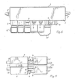
- the plug connection is designed such that the plug connection formed from a cuboid housing 1 consists of a housing middle part 2 designed as a plug comb with detachably fastened and interconnected plug-in receptacle connections 13 and plug-in connections 13 '(see FIGS.
- middle part 2 two upper cable holders 3 and lower plug-in catches 4 are arranged in series on both sides.
- the middle part 2 are on both sides lockable, box-shaped, on the one hand a low voltage and on the other hand a normal voltage part enclosing cover shells 5, which in the area of the cable holder 3 of the middle part 2 provided with fastening elements 2 ⁇ have open cable penetration recesses 6 towards the middle part and which underneath the plug connection catches 4 arranged in series with one each extending over the entire length of the cover shells 5 plug receptacle receptacles 8 are provided.
- Both the plug-in receptacle and plug-in connections 13, 13 'and also the plug-in catches 4 are dimensioned or arranged with corresponding single or multiple grid dimensions.
- the middle part 2 is expediently designed in the form of a wall 2 'separating the interiors 5' of the attached cover shell 5 '.
- the two large plug-in recesses 8 of the shells 5 are at least partially provided with individual, the grid dimension corresponding recess closures 9, which correspond in their width B to the width of the plug-in connections 13 'and the plug-in connections 4 which remain free of plug-in connections are releasably latched.
- the shape of these recess closures 9 can be seen from Fig.
- plug-in receptacles 13 which can also be plugged with their openings 9 'on plug receptacle connections 13 remaining plug-in catches 4.
- plug-in receptacles 13 are provided on the upper side with suitable plug-in grooves 13 'with which the connections 13 are plugged onto the catches 4 from the side.
- the cover shells 5 are provided with cable penetration recesses 6 open towards the middle part, as mentioned above, which Recesses are provided with insertable closures 7. If, for example, the connection between the plug connection and the control device requires only two cables 15 to be led out, so the free recesses 6 remain closed with the associated retractable closures 7. If a regulating and control device requires four cable connections 15 due to more extensive regulating and control functionality, then all four existing recesses 6 can be used for the passage of the cables 15. In such a case, for example, the entire length of the recesses 8 can also be used for the arrangement of plug-in receptacle connections 13, so that in this case the arrangement of the aforementioned recess closures 9 becomes unnecessary.
- shell support pins 10 are arranged on both sides on the central part 2 and on the inside on the shells 5 as shown in FIG. 3.
- the tongue-like latching elements 11 advantageously had push-button extensions 13, with the aid of which the tongue-like latching elements 11 are easily accessible from the outside and can be depressed in order to be able to pull the relevant plug-in connector 13 'easily out of its associated plug-in connector 13. If insert Connections 13 ⁇ , in the grid dimensions are correspondingly twice as wide as the other plug-in connections 13 ', these wider plug-in connections 13' are advantageously provided with the bow-like latching elements 12, which are then assigned 5 tongue-like latching elements 11 at the appropriate location of the shells.
- plug-in receptacle and plug-in connections 13, 13 'with respect to their actual receptacle and plug-in parts are provided with different mechanically coded plug-in cross-sections at least with respect to the low-voltage and the normal-voltage side.
- FIG. 2 shows the connections 13, among other things.
- this mechanical coding of the plug cross-sections also ensures that the plug-in connections at the plug connection cannot go wrong.
- the housing middle part 2 is provided at its lateral ends with fasteners 2 '.
- the middle part 2 does not offer completely identical connection options, on the other hand the correct assignment of the respective shell 5 should be taken into account in a simple manner, the middle part 2 and the two shells 5, as can be seen from FIG. 2, are provided with mutually offset push-on orientation projections 17 which only allow the shells 5 to be fitted on the side of the central part 2 intended for them.
Landscapes
- Connector Housings Or Holding Contact Members (AREA)
- Details Of Connecting Devices For Male And Female Coupling (AREA)
Applications Claiming Priority (2)
| Application Number | Priority Date | Filing Date | Title |
|---|---|---|---|
| DE8811904U DE8811904U1 (de) | 1988-09-20 | 1988-09-20 | Steckeranschluß |
| DE8811904U | 1988-09-20 |
Publications (2)
| Publication Number | Publication Date |
|---|---|
| EP0360089A2 true EP0360089A2 (fr) | 1990-03-28 |
| EP0360089A3 EP0360089A3 (fr) | 1991-07-03 |
Family
ID=6828123
Family Applications (1)
| Application Number | Title | Priority Date | Filing Date |
|---|---|---|---|
| EP19890116599 Withdrawn EP0360089A3 (fr) | 1988-09-20 | 1989-09-08 | Connexion à fiches |
Country Status (2)
| Country | Link |
|---|---|
| EP (1) | EP0360089A3 (fr) |
| DE (1) | DE8811904U1 (fr) |
Family Cites Families (4)
| Publication number | Priority date | Publication date | Assignee | Title |
|---|---|---|---|---|
| GB2064879B (en) * | 1979-11-27 | 1983-07-20 | Brookes & Gatehouse | Display and/or control unit |
| US4369340A (en) * | 1980-09-04 | 1983-01-18 | Bell Telephone Laboratories, Incorporated | Wall telephone adapter assembly |
| GB2126016B (en) * | 1982-08-31 | 1986-03-12 | Lero Engineering Limited | Electrical control unit |
| US4820192A (en) * | 1988-06-10 | 1989-04-11 | American Telephone And Telegraph Company | Connecting block construction |
-
1988
- 1988-09-20 DE DE8811904U patent/DE8811904U1/de not_active Expired - Lifetime
-
1989
- 1989-09-08 EP EP19890116599 patent/EP0360089A3/fr not_active Withdrawn
Also Published As
| Publication number | Publication date |
|---|---|
| EP0360089A3 (fr) | 1991-07-03 |
| DE8811904U1 (de) | 1990-01-25 |
Similar Documents
| Publication | Publication Date | Title |
|---|---|---|
| DE69825349T2 (de) | Motoransteuerbaugruppe | |
| DE3004372C2 (fr) | ||
| DE69219791T2 (de) | Modulare auswechselbare Energieverteilungsvorrichtung | |
| DE60300009T2 (de) | Verbindungsvorrichtung eines elektronischen Moduls | |
| DE2825673C2 (de) | Beweglicher Raumteiler mit elektrischen Installationselementen | |
| DE3807645C2 (de) | Steckverbindungssystem für elektrische Leiter | |
| EP0888706B1 (fr) | Controleur programmable | |
| DE3334097C1 (de) | Zentraler Stromverteiler fuer die Verdrahtung von Kraftfahrzeugen | |
| DE69600047T2 (de) | Zusammensetzbare elektrische Schnittstellenvorrichtung | |
| DE69214493T2 (de) | Sicherungshaltergehäuse modularer Struktur | |
| DE4227182C1 (de) | Zentraleinheit | |
| EP0338259A2 (fr) | Unité de commande composée de plusieurs modules arrangés les uns à côté des autres sur un support | |
| DE3224954A1 (de) | Steckkarten-sockel | |
| DE3216217A1 (de) | Modulstecker | |
| EP0474082A1 (fr) | Dispositif de codage avec des contacts spéciaux intégrés pour assemblages électriques enfichables sur un câblage de panneau arrière | |
| DE2400634C2 (de) | Vorrichtung zur Halterung und Speisung von logischen Zellen | |
| EP0183939A2 (fr) | Connecteur multicontacts muni d'un capot de protection qui peut y être fixé | |
| DE69026161T2 (de) | Energieverteilungsvorrichtung für Systemmöbeleinheiten | |
| DE3641153C2 (fr) | ||
| DE3901285C2 (fr) | ||
| DE2445381C2 (de) | Fernmeldekabel-endverschluss | |
| DE2907207B2 (de) | Umschaltsteckverbindung | |
| DE2647777C2 (de) | Kombination von Elektroinstallationsgeräten | |
| DE2833777B1 (de) | Mechanische Codiereinrichtung | |
| DE3816853C1 (en) | Cover for the connecting pins of connector strips |
Legal Events
| Date | Code | Title | Description |
|---|---|---|---|
| PUAI | Public reference made under article 153(3) epc to a published international application that has entered the european phase |
Free format text: ORIGINAL CODE: 0009012 |
|
| AK | Designated contracting states |
Kind code of ref document: A2 Designated state(s): AT BE CH FR GB LI LU NL |
|
| PUAL | Search report despatched |
Free format text: ORIGINAL CODE: 0009013 |
|
| AK | Designated contracting states |
Kind code of ref document: A3 Designated state(s): AT BE CH FR GB LI LU NL |
|
| STAA | Information on the status of an ep patent application or granted ep patent |
Free format text: STATUS: THE APPLICATION IS DEEMED TO BE WITHDRAWN |
|
| 18D | Application deemed to be withdrawn |
Effective date: 19920104 |