EP0360097A1 - Deckenstrahlplatte - Google Patents
Deckenstrahlplatte Download PDFInfo
- Publication number
- EP0360097A1 EP0360097A1 EP89116641A EP89116641A EP0360097A1 EP 0360097 A1 EP0360097 A1 EP 0360097A1 EP 89116641 A EP89116641 A EP 89116641A EP 89116641 A EP89116641 A EP 89116641A EP 0360097 A1 EP0360097 A1 EP 0360097A1
- Authority
- EP
- European Patent Office
- Prior art keywords
- ceiling panel
- steel
- radiant ceiling
- steel sheet
- troughs
- Prior art date
- Legal status (The legal status is an assumption and is not a legal conclusion. Google has not performed a legal analysis and makes no representation as to the accuracy of the status listed.)
- Granted
Links
- 229910000831 Steel Inorganic materials 0.000 claims abstract description 48
- 239000010959 steel Substances 0.000 claims abstract description 48
- 238000010438 heat treatment Methods 0.000 claims abstract description 7
- 238000003466 welding Methods 0.000 description 3
- 238000009413 insulation Methods 0.000 description 2
- 239000000725 suspension Substances 0.000 description 2
- 238000010276 construction Methods 0.000 description 1
- 238000009826 distribution Methods 0.000 description 1
- 239000000428 dust Substances 0.000 description 1
- 230000002349 favourable effect Effects 0.000 description 1
- 238000004519 manufacturing process Methods 0.000 description 1
- 239000002184 metal Substances 0.000 description 1
- 230000002787 reinforcement Effects 0.000 description 1
- 238000004904 shortening Methods 0.000 description 1
Images
Classifications
-
- F—MECHANICAL ENGINEERING; LIGHTING; HEATING; WEAPONS; BLASTING
- F24—HEATING; RANGES; VENTILATING
- F24D—DOMESTIC- OR SPACE-HEATING SYSTEMS, e.g. CENTRAL HEATING SYSTEMS; DOMESTIC HOT-WATER SUPPLY SYSTEMS; ELEMENTS OR COMPONENTS THEREFOR
- F24D3/00—Hot-water central heating systems
- F24D3/12—Tube and panel arrangements for ceiling, wall, or underfloor heating
- F24D3/16—Tube and panel arrangements for ceiling, wall, or underfloor heating mounted on, or adjacent to, a ceiling, wall or floor
- F24D3/165—Suspended radiant heating ceiling
-
- Y—GENERAL TAGGING OF NEW TECHNOLOGICAL DEVELOPMENTS; GENERAL TAGGING OF CROSS-SECTIONAL TECHNOLOGIES SPANNING OVER SEVERAL SECTIONS OF THE IPC; TECHNICAL SUBJECTS COVERED BY FORMER USPC CROSS-REFERENCE ART COLLECTIONS [XRACs] AND DIGESTS
- Y02—TECHNOLOGIES OR APPLICATIONS FOR MITIGATION OR ADAPTATION AGAINST CLIMATE CHANGE
- Y02B—CLIMATE CHANGE MITIGATION TECHNOLOGIES RELATED TO BUILDINGS, e.g. HOUSING, HOUSE APPLIANCES OR RELATED END-USER APPLICATIONS
- Y02B30/00—Energy efficient heating, ventilation or air conditioning [HVAC]
Definitions
- the invention relates to a radiant ceiling panel, in which steel tubes through which a heating medium flows are welded in troughs of a profiled steel sheet arranged at a distance from one another.
- Radiant ceiling panels consist of a profiled steel sheet with spot welded steel pipes. To accommodate insulation, the side edges of the steel sheet are bent upwards at right angles and additionally stiffened by a flange, which can also be used to hold down the insulation. Crossbars are welded into the steel sheet for fastening and additional stiffening. Collection boxes are provided on the end faces of the pipes.
- Radiant ceiling panels have proven themselves as large space heating, eg for halls, and other areas of application of radiant heating. You have high economic speed. They have short heating-up times, good controllability and favorable temperature distribution in the room, even in the vertical direction. Radiant ceiling panels cause no air movement and therefore no dust and are draft-free. Because they are installed on the ceiling, they do not take up any space on the floor or wall.
- the steel tubes are in troughs, each of which has a cross section in the form of a half cylinder.
- the half-cylinder jacket is protruded outwards / downwards from the underside of the flat steel sheet.
- This version affects the otherwise smooth and clear lines, which also result from the invisibility of the suspension device.
- intimate contact between the tubes and the steel sheet is not achieved in the entire area of the trough.
- the course of the spot weld remains disruptively visible even at great heights.
- the invention seeks to remedy this.
- the invention has for its object a radiant ceiling panel of the type mentioned without projections on the underside of the steel to create sheet metal.
- this object is achieved in that the troughs with their outermost - bottom - boundary surfaces and lines are arranged in the plane of the underside of the steel sheet, in which they form a shadow gap on each long side essentially by the amount of a radius the steel pipes are pressed inwards.
- the underside of the steel sheet forms the most protruding point in the space in which the radiant ceiling panel is arranged.
- the radiant ceiling panel also advantageously fits into otherwise smooth ceiling constructions or cassette or panel ceilings with their shadow gaps.
- the shadow gaps also give the radiant ceiling panel a larger heating surface, which results in greater downward heat emission.
- the shadow gaps also result in greater stability of the radiant ceiling panel; there are fewer folds.
- the steel tubes are welded to the steel sheet in the area of the shadow gaps.
- the welding can be done for each pipe in only one shadow gap; however, it is useful in both.
- the radiant ceiling panel is also aesthetically improved as a result.
- two weld lines in the shadow gaps are possible instead of a weld line at the apex of the pipe; the heat transfer and thus the performance is improved; because there is a closer contact between the pipes and the steel sheet, and a shortening of the heat transfer paths to the flat part of the steel sheet.
- a radiant ceiling panel consists of a steel sheet 1 to which steel pipes 2 are welded.
- the lateral edges 11 of the steel sheet 1 are bent upwards at right angles and additionally stiffened by a flange 12.
- Troughs 13 are provided in the steel plate 1 parallel to the edges 11 at a constant distance.
- the troughs 13 are arranged with their outermost - lowermost - boundary surfaces 14 in the plane of the underside 15 of the steel sheet 1.
- the troughs 13 are pressed into the steel sheet 1 to form a shadow gap 16 on each longitudinal side, at least by the amount of a half-diameter of the steel tubes 2.
- each trough 13 is designed as a half cylinder 17.
- the inside diameter of the half cylinder 17 is equal to the outside diameter of the steel tube 2 accommodated by the trough 13.
- each trough 13 is designed as a trapezoid 18.
- the height of the trapezoid 18 is equal to the outer radius of the steel tube 2 that is accommodated.
- the steel tube 2 lies on the two side walls 19 except on the underside 15.
- the side walls 19 bear against the steel tube 2 as tangential surfaces.
- the side walls 19 At the left darge trough 13 are the side walls 19 in the area in which they rest on the steel tube 2, formed as a partial cylinder 20.
- the steel tubes 2 are flowed through by a heating medium. Each of the steel tubes 2 is welded into one of the troughs 13.
- the steel tubes 2 are advantageously welded to the steel sheet 1 in the area of the shadow gaps 16, in the embodiment according to FIG. 3 along the contact lines.
- the steel tubes 2 open at one end in a collecting box 3.
- Several of the radiant ceiling panels shown can be connected in series in the longitudinal direction. The end of such a series connection of radiant ceiling panels each forms a collecting box 3.
- suspension crosspieces 4 are welded in the longitudinal direction at a distance from one another into the steel sheet 1.
- the radiant ceiling panel serves as a large space heater, e.g. for halls and similar buildings.
Landscapes
- Engineering & Computer Science (AREA)
- Physics & Mathematics (AREA)
- Thermal Sciences (AREA)
- Chemical & Material Sciences (AREA)
- Combustion & Propulsion (AREA)
- Mechanical Engineering (AREA)
- General Engineering & Computer Science (AREA)
- Steam Or Hot-Water Central Heating Systems (AREA)
- Butt Welding And Welding Of Specific Article (AREA)
- Vehicle Interior And Exterior Ornaments, Soundproofing, And Insulation (AREA)
- Domestic Hot-Water Supply Systems And Details Of Heating Systems (AREA)
Abstract
Description
- Die Erfindung betrifft eine Deckenstrahlplatte, bei der in parallel zueinander im Abstand angeordnete Mulden eines profilierten Stahlblechs von einem Heizmedium durchströmte Stahlrohre geschweißt sind.
- Deckenstrahlplatten bestehen aus einem profilierten Stahlblech mit punktmäßig eingeschweißten Stahlrohren. Zur Aufnahme einer Isolierung sind die seitlichen Ränder des Stahlblechs nach oben rechtwinklig abgekantet und durch eine Umbördelung zusätzlich versteift, die auch zum Niederhalten der Isolierung benutzt werden kann. Für die Befestigung und die zusätzliche Versteifung sind Aufhängequerstege in das Stahlblech eingeschweißt. An den Stirnseiten der Rohre sind Sammelkästen vorgesehen.
- Deckenstrahlplatten haben sich als Großraumheizung, z.B. für Hallen, und andere Anwendungsgebiete der Strahlheizung bewährt. Sie haben hohe Wirtschaftlich keit. Sie weisen kurze Aufheizzeiten, gute Regelbarkeit und günstige Temperaturverteilung im Raum auf, auch in vertikaler Richtung. Deckenstrahlplatten verursachen keine Luftbewegung und somit keine Staubaufwirbelung und sind zugfrei. Durch die Installation an der Decke haben sie keinen Platzbedarf auf dem Boden oder der Wand.
- Bei den bekannten Deckenstrahlplatten liegen die Stahlrohre in Mulden, von denen jede einen querschnitt in der Form eines Halbzylinders aufweist. Der Halbzylindermantel ist aus der Unterseite des ebenen Stahlblechs nach außen/unten vorgestülpt. Diese Ausführung beeinträchtigt die ansonsten glatte und klare Linienführung, die sich auch durch die Unsichtbarkeit der Aufhängevorrichtung ergibt. Außerdem wird bei der üblichen Schweißung im Scheitelpunkt jedes Rohres eine innige Berührung der Rohre mit dem Stahlblech im ganzen Bereich der Mulde nicht erreicht. Hinzu kommt, daß der Verlauf der Punktschweißung auch in großer Höhe störend sichtbar bleibt.
- Hier will die Erfindung Abhilfe schaffen. Der Erfindung liegt die Aufgabe zugrunde, eine Deckenstrahlplatte der eingangs genannten Art ohne Vorsprünge über die Unterseite des Stahl blechs hinaus zu schaffen. Gemäß der Erfindung wird diese Aufgabe dadurch gelöst, daß die Mulden mit ihren äußersten - untersten - Begrenzungsflächen und -linien in der Ebene der Unterseite des Stahlblechs angeordnet sind, in das sie unter Bildung je einer Schattenfuge auf jeder Längsseite im wesentlichen um den Betrag eines Halbmessers der Stahlrohre nach innen gedrückt sind.
- Bei der Erfindung bildet die Unterseite des Stahlblechs die am weitesten in den Raum, in dem die Deckenstrahlplatte angeordnet ist, hineinragende Stelle.
- Diese ist als Fläche - ohne Vorsprünge - ausgebildet. Es ergibt sich eine glatte und klare Linienführung. Auch in im übrigen glatte Deckenkonstruktionen bzw. Kassetten- oder paneeldecken mit ihren Schattenfugen fügt sich die Deckenstrahlplatte vorteilhaft ein. Die Schattenfugen geben der Deckenstrahlplatte darüber hinaus eine größere Heizfläche, was eine größere Wärmeabgabe nach unten zur Folge hat. Die Schattenfugen haben auch eine größere Stabilität der Deckenstrahlplatte zur Folge; es tritt weniger Faltenwurf auf.
- In Weiterbildung der Erfindung sind die Stahlrohre mit dem Stahlblech im Bereich der Schattenfugen verschweißt. Das Verschweißen kann für jedes Rohr in nur einer Schattenfuge erfolgen; zweckmäßig erfolgt es jedoch in beiden. Dadurch, daß bei dieser Weiterbildung die Schweißpunkte in der Schattenfuge liegen, sind die nicht mehr sichtbar, jedenfalls nicht mehr nach der Aufhängung der Deckenstrahlplatte. Die Deckenstrahlplatte ist auch hierdurch ästhetisch weiter verbessert. Dadurch, daß zwei Schweißlinien in den Schattenfugen anstelle einer Schweißlinie im Scheitelpunkt des Rohres möglich sind; wird die Wärmeübertragung und damit die Leistung verbessert; denn es ergibt sich einmal eine engere Anlage der Rohre an dem Stahlblech, zum anderen eine Verkürzung der Wärmeübergangswege zum ebenen Teil des Stahlblechs.
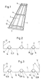
- Zwei Ausführungsbeispiele der Erfindung sind in der Zeichnung dargestellt und werde im folgenden näher beschrieben. Es zeigen:
- Fig. 1 in perspektivischer Darstellung eine Deckenstrahlplatte von oben gesehen;
- Fig. 2 die Stirnansicht einer Deckenstrahlplatte;
- Fig. 3 die Stirnansicht einer anderen Deckenstrahlplatte.
- Eine Deckenstrahlplatte besteht aus einem Stahlblech 1, mit dem Stahlrohre 2 verschweißt sind.
- Die seitlichen Ränder 11 des Stahlbelchs 1 sind nach oben rechtwinklig abgekantet und durch eine Umbördelung 12 zusätzlich versteift. Parallel zu den Rändern 11 sind in gleichbleibendem Abstand Mulden 13 in dem Stahlbelch 1 vorgesehen.
- Die Mulden 13 sind mit ihren äußersten - untersten - Begrenzungsflächen 14 in der Ebene der Unterseite 15 des Stahlbelchs 1 angeordnet. Die Mulden 13 sind in das Stahlblech 1 unter Bildung je einer Schattenfuge 16 auf jeder Längsseite mindestens um den Betrag eines Halbmessers der Stahlrohre 2 nach innen gedrückt.
- Bei der in Figur 2 dargestellten Ausführung ist jede Mulde 13 als Halbzylinder 17 ausgebildet. Der Innendurchmesser des Halbzylinders 17 ist gleich dem Außendurchmesser des von der Mulde 13 aufgenommenen Stahlrohres 2.
- Bei der in Figur 3 dargestellten Ausführung ist jede Mulde 13 als Trapez 18 ausgebildet. Die Höhe des Trapez 18 ist gleich dem Außenhalbmesser des aufgenommenen Stahlrohres 2. Das Stahlrohr 2 liegt außer an der Unterseite 15 an den beiden Seitenwänden 19 an. Bei den mittig und rechts dargestellten Mulden 13 liegen die Seitenwände 19 als Tangentialflächen an dem Stahlrohr 2 an. Bei der links darge stellten Mulde 13 sind die Seitenwände 19 in dem Bereich, in dem sie an dem Stahlrohr 2 anliegen, als Teilzylinder 20 ausgebildet.
- Die Stahlrohre 2 sind von einem Heizmedium durchströmt. Jedes der Stahlrohre 2 ist in eine der Mulden 13 geschweißt. Vorteilhaft sind die Stahlrohre 2 min dem Stahlblech 1 im Bereich der Schattenfugen 16 verschweißt, bei der Ausführung nach Figur 3 entlang den Berührungslinien.
- Im Ausführungsbeispiel münden die Stahlrohre 2 an einer Stirnseite in einem Sammelkasten 3. Mehrere der dargestellten Deckenstrahlplatten können in Längsrichtung hintereinander geschaltet sein. Das Ende einer solchen Hintereinaderschaltung von Deckenstrahlplatten bildet jeweils ein Sammelkasten 3. Für die Befestigung der Deckenstrahlplatte an einer nicht dargestellten Decke und für die zusätzliche Versteifung sind Aufhängequerstege 4 in Längsrichtung im Abstand voneinander in das Stahlblech 1 geschweißt.
- Alle Ausführungen der Deckenstrahlplatte können mit Hilfe von Wechseleinsätzen in demselben Werkzeug hergestellt werden. Bei gleichen Investitions- und Fertigungskosten ergeben sich folglich zwei Varianten der Deckenstrahlplatte, von denen eine noch einmal eine Untervariante aufweist.
- Die Deckenstrahlplatte dient als Großraumheizung, z.B. für Hallen und ähnliche Gebäude.
Claims (5)
Priority Applications (1)
| Application Number | Priority Date | Filing Date | Title |
|---|---|---|---|
| AT89116641T ATE82379T1 (de) | 1988-09-13 | 1989-09-08 | Deckenstrahlplatte. |
Applications Claiming Priority (2)
| Application Number | Priority Date | Filing Date | Title |
|---|---|---|---|
| DE8811570U DE8811570U1 (de) | 1988-09-13 | 1988-09-13 | Deckenstrahlplatte |
| DE8811570U | 1988-09-13 |
Publications (2)
| Publication Number | Publication Date |
|---|---|
| EP0360097A1 true EP0360097A1 (de) | 1990-03-28 |
| EP0360097B1 EP0360097B1 (de) | 1992-11-11 |
Family
ID=6827871
Family Applications (1)
| Application Number | Title | Priority Date | Filing Date |
|---|---|---|---|
| EP89116641A Expired - Lifetime EP0360097B1 (de) | 1988-09-13 | 1989-09-08 | Deckenstrahlplatte |
Country Status (3)
| Country | Link |
|---|---|
| EP (1) | EP0360097B1 (de) |
| AT (1) | ATE82379T1 (de) |
| DE (2) | DE8811570U1 (de) |
Cited By (2)
| Publication number | Priority date | Publication date | Assignee | Title |
|---|---|---|---|---|
| EP1167885A2 (de) | 2000-06-30 | 2002-01-02 | H. Dr.Ing. Vollmer | Strahelement zum Abstrahlen von Wärme und/oder Kälte |
| EP1857743A1 (de) * | 2006-05-17 | 2007-11-21 | OFFICINE TERMOTECNICHE FRACCARO O.T.F. S.r.l. | Strahlungstafeln und Verfahren zur Bereitstellung von Strahlungstafeln |
Families Citing this family (5)
| Publication number | Priority date | Publication date | Assignee | Title |
|---|---|---|---|---|
| DE3877204D1 (de) * | 1988-11-09 | 1993-02-11 | Zehnder Beutler Gmbh | Deckenstrahlplatte sowie verfahren und vorrichtung zu ihrer herstellung. |
| DE10024507B4 (de) * | 1999-06-28 | 2010-05-27 | Kochendörfer, Christoph, Dipl.-Ing. | Strahlflächenaufbau |
| DE202004013206U1 (de) | 2004-08-23 | 2004-10-28 | Frenger Systemen BV Heiz- und Kühltechnik GmbH | Strahlflächenaufbau |
| EP2762787A3 (de) * | 2013-01-31 | 2016-09-21 | Barcol-Air AG | Klimaelement für eine Heiz- und Kühldecke |
| DE102016121953A1 (de) * | 2016-11-15 | 2018-05-17 | Haufe Deckensysteme Gmbh | Decken- und/oder Wandverkleidung und Herstellungsverfahren hierfür |
Citations (2)
| Publication number | Priority date | Publication date | Assignee | Title |
|---|---|---|---|---|
| CH382945A (de) * | 1961-03-30 | 1964-10-15 | Apparate Und Metallbau Wald Ag | Heizungsanlage |
| DE2138667A1 (de) * | 1971-08-03 | 1973-02-22 | Rinker Baufa Werke | Verfahren und vorrichtung zur grossraumbeheizung und -belueftung |
Family Cites Families (1)
| Publication number | Priority date | Publication date | Assignee | Title |
|---|---|---|---|---|
| DE8107396U1 (de) * | 1981-03-14 | 1981-09-17 | Baufa-Werke Richard Rinker, 5750 Menden | Aufhängevorrichtung an einem Deckenstrahlheizkörper |
-
1988
- 1988-09-13 DE DE8811570U patent/DE8811570U1/de not_active Expired
-
1989
- 1989-09-08 AT AT89116641T patent/ATE82379T1/de active
- 1989-09-08 EP EP89116641A patent/EP0360097B1/de not_active Expired - Lifetime
- 1989-09-08 DE DE8989116641T patent/DE58902688D1/de not_active Expired - Lifetime
Patent Citations (2)
| Publication number | Priority date | Publication date | Assignee | Title |
|---|---|---|---|---|
| CH382945A (de) * | 1961-03-30 | 1964-10-15 | Apparate Und Metallbau Wald Ag | Heizungsanlage |
| DE2138667A1 (de) * | 1971-08-03 | 1973-02-22 | Rinker Baufa Werke | Verfahren und vorrichtung zur grossraumbeheizung und -belueftung |
Cited By (3)
| Publication number | Priority date | Publication date | Assignee | Title |
|---|---|---|---|---|
| EP1167885A2 (de) | 2000-06-30 | 2002-01-02 | H. Dr.Ing. Vollmer | Strahelement zum Abstrahlen von Wärme und/oder Kälte |
| DE10031980B4 (de) * | 2000-06-30 | 2004-04-29 | Vollmer, H., Dr.-Ing. | Strahlelement zum Abstrahlen von Wärme und/oder Kälte |
| EP1857743A1 (de) * | 2006-05-17 | 2007-11-21 | OFFICINE TERMOTECNICHE FRACCARO O.T.F. S.r.l. | Strahlungstafeln und Verfahren zur Bereitstellung von Strahlungstafeln |
Also Published As
| Publication number | Publication date |
|---|---|
| DE58902688D1 (de) | 1992-12-17 |
| EP0360097B1 (de) | 1992-11-11 |
| ATE82379T1 (de) | 1992-11-15 |
| DE8811570U1 (de) | 1988-11-03 |
Similar Documents
| Publication | Publication Date | Title |
|---|---|---|
| DE2846549A1 (de) | Waermeaustauscher mit rohrschlangen, die zwischen zwei tragwaenden angeordnet sind | |
| EP0360097B1 (de) | Deckenstrahlplatte | |
| DE3737187A1 (de) | Winkelprofilfoermige lasche zum aneinanderstossenden verbinden von lochprofilen | |
| DE2138966B2 (de) | Vorgefertigte Flanschverbindung | |
| EP0177904B1 (de) | Vorrichtung zum Austausch der Wärme zwischen zwei im Kreuzstrom zueinander geführten Gasen | |
| DE2734348C3 (de) | Metallfolienisolierung, insbesondere für Kernreaktoranlagen | |
| DE4015830C2 (de) | Wärmetauscher, insbesondere Wasser/Luft-Kühler | |
| DE8906539U1 (de) | Deckenstrahlplatte | |
| EP0045491B1 (de) | Raumheizgerät für Kleinräume | |
| EP0143150B1 (de) | Flanschverbindung | |
| DE2424340C2 (de) | Verriegelungsvorrichtung für Kompaktfilterzellen | |
| DE9000698U1 (de) | Deckenstrahlplatte | |
| EP0445337A1 (de) | Heizkörper | |
| EP0255039B1 (de) | Fussboden-Flächenheizung | |
| EP0171558A2 (de) | Wärmeübertrager | |
| EP0371148B1 (de) | Deckenstrahlplatte sowie Verfahren und Vorrichtung zu ihrer Herstellung | |
| DE2503006A1 (de) | Bauelementensatz zum herstellen von fussbodenheizungen | |
| DE3801299C2 (de) | Metallkanal, insbesondere Kabelkanal, in Form eines U-Profils o. dgl. | |
| DE9005960U1 (de) | Deckenstrahlplatte | |
| CH683126A5 (de) | Heizrohr zur Bildung einer Heizwand. | |
| EP1704370A1 (de) | Flächenelement zur temperierung von raumluft | |
| DE2065838C3 (de) | Vorrichtung zum Abstützen von die äußere Schale eines zweischaligen Flachdaches bildenden Dacheindeckungsplatten | |
| DE3231322C2 (de) | Innenrippenrohr für druckgas - oder druckölbeheizte Heizkessel | |
| EP0532460B1 (de) | Kabelträger für Installationen in Gebäuden | |
| AT262564B (de) | Außenmauerverkleidung für Gebäude |
Legal Events
| Date | Code | Title | Description |
|---|---|---|---|
| PUAI | Public reference made under article 153(3) epc to a published international application that has entered the european phase |
Free format text: ORIGINAL CODE: 0009012 |
|
| AK | Designated contracting states |
Kind code of ref document: A1 Designated state(s): AT BE CH DE ES FR GB GR IT LI LU NL SE |
|
| 17P | Request for examination filed |
Effective date: 19900910 |
|
| 17Q | First examination report despatched |
Effective date: 19910711 |
|
| GRAA | (expected) grant |
Free format text: ORIGINAL CODE: 0009210 |
|
| AK | Designated contracting states |
Kind code of ref document: B1 Designated state(s): AT BE CH DE ES FR GB GR IT LI LU NL SE |
|
| PG25 | Lapsed in a contracting state [announced via postgrant information from national office to epo] |
Ref country code: GR Free format text: LAPSE BECAUSE OF FAILURE TO SUBMIT A TRANSLATION OF THE DESCRIPTION OR TO PAY THE FEE WITHIN THE PRESCRIBED TIME-LIMIT Effective date: 19921111 Ref country code: ES Free format text: THE PATENT HAS BEEN ANNULLED BY A DECISION OF A NATIONAL AUTHORITY Effective date: 19921111 Ref country code: BE Effective date: 19921111 Ref country code: SE Effective date: 19921111 |
|
| REF | Corresponds to: |
Ref document number: 82379 Country of ref document: AT Date of ref document: 19921115 Kind code of ref document: T |
|
| ET | Fr: translation filed | ||
| GBT | Gb: translation of ep patent filed (gb section 77(6)(a)/1977) | ||
| REF | Corresponds to: |
Ref document number: 58902688 Country of ref document: DE Date of ref document: 19921217 |
|
| ITF | It: translation for a ep patent filed | ||
| PG25 | Lapsed in a contracting state [announced via postgrant information from national office to epo] |
Ref country code: GB Effective date: 19930908 |
|
| PLBE | No opposition filed within time limit |
Free format text: ORIGINAL CODE: 0009261 |
|
| STAA | Information on the status of an ep patent application or granted ep patent |
Free format text: STATUS: NO OPPOSITION FILED WITHIN TIME LIMIT |
|
| PG25 | Lapsed in a contracting state [announced via postgrant information from national office to epo] |
Ref country code: LU Free format text: LAPSE BECAUSE OF NON-PAYMENT OF DUE FEES Effective date: 19930930 |
|
| 26N | No opposition filed | ||
| GBPC | Gb: european patent ceased through non-payment of renewal fee |
Effective date: 19930908 |
|
| REG | Reference to a national code |
Ref country code: CH Ref legal event code: PUE Owner name: HARALD KLOSTERMANN TRANSFER- BAUFA-WERK GMBH |
|
| NLS | Nl: assignments of ep-patents |
Owner name: BAUFA-WERKE GMBH |
|
| REG | Reference to a national code |
Ref country code: FR Ref legal event code: TP |
|
| PGFP | Annual fee paid to national office [announced via postgrant information from national office to epo] |
Ref country code: AT Payment date: 19970923 Year of fee payment: 9 |
|
| PGFP | Annual fee paid to national office [announced via postgrant information from national office to epo] |
Ref country code: FR Payment date: 19970924 Year of fee payment: 9 |
|
| PGFP | Annual fee paid to national office [announced via postgrant information from national office to epo] |
Ref country code: CH Payment date: 19971010 Year of fee payment: 9 |
|
| PG25 | Lapsed in a contracting state [announced via postgrant information from national office to epo] |
Ref country code: AT Free format text: LAPSE BECAUSE OF NON-PAYMENT OF DUE FEES Effective date: 19980908 |
|
| PG25 | Lapsed in a contracting state [announced via postgrant information from national office to epo] |
Ref country code: CH Free format text: LAPSE BECAUSE OF NON-PAYMENT OF DUE FEES Effective date: 19980930 Ref country code: LI Free format text: LAPSE BECAUSE OF NON-PAYMENT OF DUE FEES Effective date: 19980930 |
|
| PGFP | Annual fee paid to national office [announced via postgrant information from national office to epo] |
Ref country code: NL Payment date: 19980930 Year of fee payment: 10 |
|
| REG | Reference to a national code |
Ref country code: CH Ref legal event code: PL |
|
| PG25 | Lapsed in a contracting state [announced via postgrant information from national office to epo] |
Ref country code: FR Free format text: LAPSE BECAUSE OF NON-PAYMENT OF DUE FEES Effective date: 19990531 |
|
| REG | Reference to a national code |
Ref country code: FR Ref legal event code: ST |
|
| PG25 | Lapsed in a contracting state [announced via postgrant information from national office to epo] |
Ref country code: NL Free format text: LAPSE BECAUSE OF NON-PAYMENT OF DUE FEES Effective date: 20000401 |
|
| NLV4 | Nl: lapsed or anulled due to non-payment of the annual fee |
Effective date: 20000401 |
|
| PG25 | Lapsed in a contracting state [announced via postgrant information from national office to epo] |
Ref country code: IT Free format text: LAPSE BECAUSE OF NON-PAYMENT OF DUE FEES Effective date: 20050908 |
|
| PGFP | Annual fee paid to national office [announced via postgrant information from national office to epo] |
Ref country code: DE Payment date: 20071122 Year of fee payment: 19 |
|
| PG25 | Lapsed in a contracting state [announced via postgrant information from national office to epo] |
Ref country code: DE Free format text: LAPSE BECAUSE OF NON-PAYMENT OF DUE FEES Effective date: 20090401 |