EP0360105A2 - Vorrichtung zur Überführung von Brennstäben aus einem ersten Behältnis in ein zweites Behältnis - Google Patents
Vorrichtung zur Überführung von Brennstäben aus einem ersten Behältnis in ein zweites Behältnis Download PDFInfo
- Publication number
- EP0360105A2 EP0360105A2 EP89116706A EP89116706A EP0360105A2 EP 0360105 A2 EP0360105 A2 EP 0360105A2 EP 89116706 A EP89116706 A EP 89116706A EP 89116706 A EP89116706 A EP 89116706A EP 0360105 A2 EP0360105 A2 EP 0360105A2
- Authority
- EP
- European Patent Office
- Prior art keywords
- container
- fuel rods
- trough
- shaped
- ventilation partition
- Prior art date
- Legal status (The legal status is an assumption and is not a legal conclusion. Google has not performed a legal analysis and makes no representation as to the accuracy of the status listed.)
- Granted
Links
- 239000000446 fuel Substances 0.000 title abstract description 11
- 238000009423 ventilation Methods 0.000 claims abstract description 19
- 238000005192 partition Methods 0.000 claims abstract description 18
- 239000002915 spent fuel radioactive waste Substances 0.000 claims abstract description 7
- 230000002285 radioactive effect Effects 0.000 abstract description 5
- 239000002245 particle Substances 0.000 abstract description 4
- 238000011109 contamination Methods 0.000 abstract description 3
- 229910001220 stainless steel Inorganic materials 0.000 description 3
- 239000010935 stainless steel Substances 0.000 description 3
- 238000005516 engineering process Methods 0.000 description 1
- 238000007789 sealing Methods 0.000 description 1
Images
Classifications
-
- G—PHYSICS
- G21—NUCLEAR PHYSICS; NUCLEAR ENGINEERING
- G21F—PROTECTION AGAINST X-RADIATION, GAMMA RADIATION, CORPUSCULAR RADIATION OR PARTICLE BOMBARDMENT; TREATING RADIOACTIVELY CONTAMINATED MATERIAL; DECONTAMINATION ARRANGEMENTS THEREFOR
- G21F5/00—Transportable or portable shielded containers
-
- G—PHYSICS
- G21—NUCLEAR PHYSICS; NUCLEAR ENGINEERING
- G21C—NUCLEAR REACTORS
- G21C19/00—Arrangements for treating, for handling, or for facilitating the handling of, fuel or other materials which are used within the reactor, e.g. within its pressure vessel
- G21C19/32—Apparatus for removing radioactive objects or materials from the reactor discharge area, e.g. to a storage place; Apparatus for handling radioactive objects or materials within a storage place or removing them therefrom
-
- G—PHYSICS
- G21—NUCLEAR PHYSICS; NUCLEAR ENGINEERING
- G21F—PROTECTION AGAINST X-RADIATION, GAMMA RADIATION, CORPUSCULAR RADIATION OR PARTICLE BOMBARDMENT; TREATING RADIOACTIVELY CONTAMINATED MATERIAL; DECONTAMINATION ARRANGEMENTS THEREFOR
- G21F5/00—Transportable or portable shielded containers
- G21F5/005—Containers for solid radioactive wastes, e.g. for ultimate disposal
- G21F5/008—Containers for fuel elements
-
- G—PHYSICS
- G21—NUCLEAR PHYSICS; NUCLEAR ENGINEERING
- G21F—PROTECTION AGAINST X-RADIATION, GAMMA RADIATION, CORPUSCULAR RADIATION OR PARTICLE BOMBARDMENT; TREATING RADIOACTIVELY CONTAMINATED MATERIAL; DECONTAMINATION ARRANGEMENTS THEREFOR
- G21F7/00—Shielded cells or rooms
- G21F7/005—Shielded passages through walls; Locks; Transferring devices between rooms
-
- Y—GENERAL TAGGING OF NEW TECHNOLOGICAL DEVELOPMENTS; GENERAL TAGGING OF CROSS-SECTIONAL TECHNOLOGIES SPANNING OVER SEVERAL SECTIONS OF THE IPC; TECHNICAL SUBJECTS COVERED BY FORMER USPC CROSS-REFERENCE ART COLLECTIONS [XRACs] AND DIGESTS
- Y02—TECHNOLOGIES OR APPLICATIONS FOR MITIGATION OR ADAPTATION AGAINST CLIMATE CHANGE
- Y02E—REDUCTION OF GREENHOUSE GAS [GHG] EMISSIONS, RELATED TO ENERGY GENERATION, TRANSMISSION OR DISTRIBUTION
- Y02E30/00—Energy generation of nuclear origin
- Y02E30/30—Nuclear fission reactors
Definitions
- the invention relates to a device for transferring spent fuel rods from a channel-shaped first container into a second container which is docked onto a ventilation partition and is intended for final storage.
- the invention has for its object to provide a device of the type described above, by means of which it is possible to transfer fuel rods with little effort, without contamination being carried over.
- the object is achieved according to the invention by an empty, trough-shaped insert which can be moved from the final storage container into the channel-shaped container and from there filled back into the final storage container.
- spent fuel rods can be transferred from the trough-shaped container through the ventilation partition into the final storage container with little, simple constructional expenditure, without contamination of radioactive particles on any components located between the containers.
- an advantageous embodiment of the invention is that the trough-shaped insert in its jacket area has the shape of the trough-shaped container and the final storage container and its outer dimensions are smaller than the inner dimensions of the two containers so that the trough-shaped insert with easy mobility in the two containers use them as much as possible.
- fuel rods can be easily transferred in a number by which a repository is filled to the maximum in one operation.
- the room 1 designates a vertical ventilation partition which divides a work area into two separate rooms 2 and 3 which are separated from one another in terms of ventilation technology.
- the room 3 is used for handling and loading a stainless steel container 4.
- the room 2 is exposed to an open radioactive load, since the spent fuel elements that are fed into it are disassembled.
- room 2 there is a stainless steel container 5.
- the container 4 is closed in its jacket area and represents a so-called can, which is loaded into a disposal container after loading with fuel rods.
- the container 5 is trough-shaped and serves as a receptacle for a trough-shaped insert 6 made of stainless steel sheet, which receives the fuel rods to be disposed of.
- Both the container 4 and the container 5 have an opening on their front side facing the ventilation partition 1, which opening is aligned with a through opening in the ventilation partition 1 which can be closed by a hood 8.
- the container 4 is docked on the ventilation partition 1 via sealing and fastening means, not shown in the drawing.
- the container 5 has on its side opposite the ventilation partition 1 a shift linkage 9.
- the container 4 to be loaded is delivered with the insert 6 and docked onto the ventilation partition 1.
- the container 5 is docked with its front opening on the ventilation partition 1.
- the insert 6 is then pulled out of the container 4 into the container 5 via the remotely actuatable shift linkage 9.
- the spent fuel rods 7 are filled into the insert 6 and then the filled insert 6 is conveyed back into the container 4 via the remotely actuatable shift linkage 9.
- the container 4 is undocked from the ventilation partition, inserted into a final storage container and can then be sent to the final disposal.
Landscapes
- Physics & Mathematics (AREA)
- Engineering & Computer Science (AREA)
- General Engineering & Computer Science (AREA)
- High Energy & Nuclear Physics (AREA)
- Plasma & Fusion (AREA)
- Filling Of Jars Or Cans And Processes For Cleaning And Sealing Jars (AREA)
- Refuse Collection And Transfer (AREA)
- Monitoring And Testing Of Nuclear Reactors (AREA)
- Filling Or Emptying Of Bunkers, Hoppers, And Tanks (AREA)
- Fluidized-Bed Combustion And Resonant Combustion (AREA)
Abstract
Description
- Die Erfindung betrifft eine Vorrichtung zur Überführung von abgebrannten Brennstäben aus einem rinnenförmigen ersten Behältnis in ein an eine Lüftungstrennwand angedocktes, zur Endlagerung bestimmtes zweites Behältnis.
- Beim Hantieren von Brennstäben, z.B. beim Einlegen der Brennstäbe in das erste Behältnis, läßt es sich nicht vermeiden, daß von den abgebrannten Brennstäben radioaktive Partikel abfallen. Beim in der Praxis üblichen Ausschieben der Brennstäbe aus dem ersten Behältnis durch die Lüftungstrennwand in das Endlagerbehältnis tritt der Nachteil auf, daß z.B. an der Öffnung der Lüftungstrennwand befindliche, fernhantiert austauschbare Komponenten, wie Dichtungen etc., mit den von den Brennstäben in das erste Behältnis gefallenen radioaktiven Partikeln kontaminiert werden.
- Der Erfindung liegt die Aufgabe zugrunde, eine Vorrichtung der eingangs beschriebenen Art zu schaffen, durch die eine mit geringem Aufwand zu bewerkstelligende Überführung von Brennstäben möglich ist, ohne daß eine Kontaminationsverschleppung auftritt.
- Die Aufgabe wird erfindungsgemäß durch einen leer aus dem Endlagerbehältnis in das rinnenförmige Behältnis und von dort gefüllt zurück in das Endlagerbehältnis bewegbaren, trogförmigen Einsatz gelöst.
- Durch die erfindungsgemäße Vorrichtung können abgebrannte Brennstäbe mit geringem, einfachen baulichen Aufwand vom rinnenförmigen Behältnis durch die Lüftungstrennwand in das Endlagerbehältnis überführt werden, ohne daß es an irgendwelchen zwischen den Behältnissen befindlichen Bauteilen zur Kontamination mit radioaktiven Partikeln kommt.
- Eine vorteilhafte Ausführungsform der Erfindung besteht darin, daß der trogförmige Einsatz in seinem Mantelbereich die Form des rinnenförmigen Behältnisses und des Endlagerbehältnisses aufweist und in seinen äußeren Abmessungen um ein solches Maß kleiner is als die inneren Abmessungen der beiden Behältnisse, daß der trogförmige Einsatz bei leichter Beweglichkeit in den beiden Behältnissen diese räumlich größtmöglich nutzt.
Hierdurch können Brennstäbe mühelos in einer Anzahl überführt werden, durch die ein Endlagerbehältnis in einem Arbeitsgang maximal gefüllt ist. - Anhand der Zeichnung wird ein Ausführungsbeispiel der Erfindung nachstehend näher erläutert.
- Es zeigt
- Fig. 1 eine zur Überführung von Brennstäben vorhandene Vorrichtung zusammen mit einem rinnenförmigen Behältnis, einer Lüftungstrennwand und einem Endlagerbehältnis in Draufsicht,
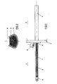
- Fig. 2 die Vorrichtung aus Fig. 1 zusammen mit dem rinnenförmigen Behältnis im vergrößerten Querschnitt.
- Mit 1 ist eine senkrechte Lüftungstrennwand bezeichnet, die einen Arbeitsbereich in zwei separate, voneinander lüftungstechnisch getrennte Räume 2 und 3 unterteilt. Der Raum 3 dient dem Hantieren und Beladen eines Edelstahlbehältnisses 4. Der Raum 2 ist mit einer offenen radioaktiven Belastung beaufschlagt, da in ihm zugeführte abgebrannte Brennelemente zerlegt werden. Im Raum 2 befindet sich ein Edelstahlbehältnis 5. Das Behältnis 4 ist in seinem Mantelbereich geschlossen und stellt eine sogenannte Büchse dar, die nach dem Beladen mit Brennstäben in einen Endlagerbehälter eingebracht wird. Das Behältnis 5 ist rinnenförmig und dient als Aufnahmebehältnis für einen trogförmigen Einsatz 6 aus Edelstahlblech, der die endzulagernden Brennstäbe aufnimmt. Sowohl das Behältnis 4 als auch das Behältnis 5 weisen an ihrer der Lüftungstrennwand 1 zugewandten Stirnseite eine Öffnung auf, die mit einer durch eine Haube 8 verschließbaren Durchgangsöffnung in der Lüftungstrennwand 1 fluchtet. Das Behältnis 4 ist an der Lüftungstrennwand 1 über zeichnerisch nicht dargestellte Dichtungs- und Besfestigungsmittel angedockt. Das Behältnis 5 weist an seiner der Lüftungstrennwand 1 entgegengesetzten Seite ein Verschiebegestänge 9 auf.
- Die Wirkungsweise des vorstehend geschilderten Ausführungsbeispiels ist wie folgt:
- Das zu beladende Behältnis 4 wird mit dem Einsatz 6 angeliefert und an die Lüftungstrennwand 1 angedockt. Nachdem die fernbetätigbare Haube 8 die Durchgangsöffung in der Lüftungstrennwand 1 freigegeben hat und auch das Behältnis 4 fernhantiert geöffnet worden ist, wird das Behältnis 5 mit seiner stirnseitigen Öffnung an die Lüftungstrennwand 1 angedockt. Über das fernbetätigbare Verschiebegestänge 9 wird dann der Einsatz 6 aus dem Behältnis 4 heraus in das Behältnis 5 gezogen. Die abgebrannten Brennstäbe 7 werden in den Einsatz 6 gefüllt und dann der gefüllte Einsatz 6 über das fernbetätigbare Verschiebegestänge 9 wieder in das Behältnis 4 zurückbefördert. Nachdem das Behältnis 5 von der Lüftungstrennwand 1 abgedockt, die Durchgangsöffnung der Lüftungstrennwand 1 durch die Haube 8 wieder geschlossen wurde und auch das Behältnis 4 wieder verschlossen ist, wird das Behältnis 4 von der Lüftungstrennwand abgedockt, in einen Endlagerbehälter eingesetzt und kann dann der bergmännischen Endlagerung zugeführt werden.
Claims (2)
Applications Claiming Priority (2)
| Application Number | Priority Date | Filing Date | Title |
|---|---|---|---|
| DE3831773 | 1988-09-19 | ||
| DE3831773 | 1988-09-19 |
Publications (3)
| Publication Number | Publication Date |
|---|---|
| EP0360105A2 true EP0360105A2 (de) | 1990-03-28 |
| EP0360105A3 EP0360105A3 (en) | 1990-08-01 |
| EP0360105B1 EP0360105B1 (de) | 1993-09-22 |
Family
ID=6363239
Family Applications (1)
| Application Number | Title | Priority Date | Filing Date |
|---|---|---|---|
| EP89116706A Expired - Lifetime EP0360105B1 (de) | 1988-09-19 | 1989-09-09 | Vorrichtung zur Überführung von Brennstäben aus einem ersten Behältnis in ein zweites Behältnis |
Country Status (5)
| Country | Link |
|---|---|
| US (1) | US5011651A (de) |
| EP (1) | EP0360105B1 (de) |
| JP (1) | JPH02162294A (de) |
| KR (1) | KR900005486A (de) |
| DE (1) | DE58905672D1 (de) |
Families Citing this family (2)
| Publication number | Priority date | Publication date | Assignee | Title |
|---|---|---|---|---|
| US5342158A (en) * | 1992-09-30 | 1994-08-30 | Gamma-Metrics | Handling and deploying radioactive sources |
| GB0020272D0 (en) * | 2000-08-18 | 2000-10-04 | Smithkline Beecham Biolog | Novel device |
Family Cites Families (8)
| Publication number | Priority date | Publication date | Assignee | Title |
|---|---|---|---|---|
| US3163312A (en) * | 1962-06-29 | 1964-12-29 | Diamond National Corp | Packing for fragile articles |
| US3466445A (en) * | 1967-10-06 | 1969-09-09 | Atomic Energy Commission | Container for radioactive fuel elements |
| US4363402A (en) * | 1981-05-08 | 1982-12-14 | Grzyll John V | Open-faced welding rod/stub receptacle |
| US4441242A (en) * | 1981-05-29 | 1984-04-10 | Westinghouse Electric Corp. | Spent fuel consolidation system |
| FR2520150A1 (fr) * | 1982-01-20 | 1983-07-22 | Alsthom Atlantique | Dispositif pour transferer horizontalement entre deux enceintes des elements combustibles nucleaires stockes en position verticale |
| US4535250A (en) * | 1984-05-30 | 1985-08-13 | The United States Of America As Represented By The United States Department Of Energy | Container for radioactive materials |
| DE3430244C2 (de) * | 1984-08-17 | 1986-11-13 | Deutsche Gesellschaft für Wiederaufarbeitung von Kernbrennstoffen mbH, 3000 Hannover | Anlage zum Beladen von Behältern mit Brennstäben oder Brennstababschnitten |
| US4676712A (en) * | 1985-06-19 | 1987-06-30 | Hayward Milton L | Positioning and locking apparatus |
-
1989
- 1989-09-09 EP EP89116706A patent/EP0360105B1/de not_active Expired - Lifetime
- 1989-09-09 DE DE89116706T patent/DE58905672D1/de not_active Expired - Fee Related
- 1989-09-18 US US07/408,524 patent/US5011651A/en not_active Expired - Fee Related
- 1989-09-18 KR KR1019890013449A patent/KR900005486A/ko not_active Withdrawn
- 1989-09-19 JP JP1240920A patent/JPH02162294A/ja active Pending
Also Published As
| Publication number | Publication date |
|---|---|
| JPH02162294A (ja) | 1990-06-21 |
| EP0360105B1 (de) | 1993-09-22 |
| EP0360105A3 (en) | 1990-08-01 |
| DE58905672D1 (de) | 1993-10-28 |
| US5011651A (en) | 1991-04-30 |
| KR900005486A (ko) | 1990-04-14 |
Similar Documents
| Publication | Publication Date | Title |
|---|---|---|
| DE2722865C2 (de) | Rohrpostförderanlage für Feingutproben | |
| EP0360105B1 (de) | Vorrichtung zur Überführung von Brennstäben aus einem ersten Behältnis in ein zweites Behältnis | |
| DE3141915C2 (de) | Lufteinlaß für eine Wärmeübertragereinheit | |
| DE2702486A1 (de) | Filtervorrichtung mit auswechselbaren filtereinsaetzen | |
| DE3727431A1 (de) | Behaeltersystem | |
| DE68906518T2 (de) | Vorrichtungen zur schnellen Aus- und Einführung von Gegenständen für einen nach aussen dicht abgeschlossenen Raum. | |
| DE8910114U1 (de) | Vorrichtung zur Überführung von Brennstäben aus einem ersten Behälter in ein zweites Behältnis | |
| DE631719C (de) | Muelleimer | |
| EP0469400B1 (de) | Einrichtung zum Sammeln einer Flüssigkeit | |
| DE2302831C2 (de) | Vorrichtung zur Handhabung von stabförmigen Elementen eines Kernreaktors | |
| EP0360106B1 (de) | Übergabesystem | |
| DE2621477B2 (de) | Automatische Waage | |
| DE2657625C2 (de) | Abfüllstation | |
| DE3009730C2 (de) | Flanschverbindung zwischen einzelabschließbaren Rohrleitungen | |
| DE1564033B1 (de) | Strahlenschutzwand | |
| DE1489821B1 (de) | Be- und Entlademaschine zum Beschicken von Brennstoffkanaelen heterogener Kernreaktoren | |
| DE202009013925U1 (de) | Einrichtung zur Entnahme von Proben sensibler Stoffe aus einem Behälter | |
| DE3111290A1 (de) | Vorrichtung zum versand von unter sich gleichen kommissionsbehaeltern | |
| DE3428278A1 (de) | Vorrichtung fuer die emissionsfreie bzw. -arme beschickung von lagerbehaeltern mit staubenden schuettguetern | |
| DE2327879C2 (de) | Vorrichtung zum Abfüllen und Überführen von genau abgemessenen Mengen von geschmolzenem Metall zu Verbraucherstellen | |
| DE2732791B2 (de) | Brennelement-Transportbehälter | |
| DE2837560C2 (de) | "Verfahren zum Verfestigen von radioaktiven Abfällen in einem Deponiebehälter" | |
| AT220258B (de) | Einheit zum Aufteilen von radioaktiven, insbesondere von Gammastrahlen aussendenden Substanzen | |
| DE2117726C3 (de) | Regal zur archivmäßigen Aufbewahrung und zur selbsttätigen Ausgabe von Tonbandkassetten und ähnlichen Behältnissen | |
| DE3911481A1 (de) | Verfahren zur entsorgung von abfaellen |
Legal Events
| Date | Code | Title | Description |
|---|---|---|---|
| PUAI | Public reference made under article 153(3) epc to a published international application that has entered the european phase |
Free format text: ORIGINAL CODE: 0009012 |
|
| AK | Designated contracting states |
Kind code of ref document: A2 Designated state(s): BE CH DE FR GB LI SE |
|
| PUAL | Search report despatched |
Free format text: ORIGINAL CODE: 0009013 |
|
| AK | Designated contracting states |
Kind code of ref document: A3 Designated state(s): BE CH DE FR GB LI SE |
|
| 17P | Request for examination filed |
Effective date: 19900625 |
|
| RAP1 | Party data changed (applicant data changed or rights of an application transferred) |
Owner name: NOELL GMBH |
|
| 17Q | First examination report despatched |
Effective date: 19930205 |
|
| GRAA | (expected) grant |
Free format text: ORIGINAL CODE: 0009210 |
|
| AK | Designated contracting states |
Kind code of ref document: B1 Designated state(s): BE CH DE FR GB LI SE |
|
| REF | Corresponds to: |
Ref document number: 58905672 Country of ref document: DE Date of ref document: 19931028 |
|
| ET | Fr: translation filed | ||
| GBT | Gb: translation of ep patent filed (gb section 77(6)(a)/1977) |
Effective date: 19940107 |
|
| PLBE | No opposition filed within time limit |
Free format text: ORIGINAL CODE: 0009261 |
|
| STAA | Information on the status of an ep patent application or granted ep patent |
Free format text: STATUS: NO OPPOSITION FILED WITHIN TIME LIMIT |
|
| 26N | No opposition filed | ||
| EAL | Se: european patent in force in sweden |
Ref document number: 89116706.6 |
|
| PGFP | Annual fee paid to national office [announced via postgrant information from national office to epo] |
Ref country code: FR Payment date: 20000807 Year of fee payment: 12 |
|
| PGFP | Annual fee paid to national office [announced via postgrant information from national office to epo] |
Ref country code: GB Payment date: 20000811 Year of fee payment: 12 Ref country code: CH Payment date: 20000811 Year of fee payment: 12 |
|
| PGFP | Annual fee paid to national office [announced via postgrant information from national office to epo] |
Ref country code: SE Payment date: 20000814 Year of fee payment: 12 |
|
| PGFP | Annual fee paid to national office [announced via postgrant information from national office to epo] |
Ref country code: BE Payment date: 20000908 Year of fee payment: 12 |
|
| PGFP | Annual fee paid to national office [announced via postgrant information from national office to epo] |
Ref country code: DE Payment date: 20000911 Year of fee payment: 12 |
|
| PG25 | Lapsed in a contracting state [announced via postgrant information from national office to epo] |
Ref country code: GB Free format text: LAPSE BECAUSE OF NON-PAYMENT OF DUE FEES Effective date: 20010909 |
|
| PG25 | Lapsed in a contracting state [announced via postgrant information from national office to epo] |
Ref country code: SE Free format text: LAPSE BECAUSE OF NON-PAYMENT OF DUE FEES Effective date: 20010910 |
|
| PG25 | Lapsed in a contracting state [announced via postgrant information from national office to epo] |
Ref country code: LI Free format text: LAPSE BECAUSE OF NON-PAYMENT OF DUE FEES Effective date: 20010930 Ref country code: CH Free format text: LAPSE BECAUSE OF NON-PAYMENT OF DUE FEES Effective date: 20010930 Ref country code: BE Free format text: LAPSE BECAUSE OF NON-PAYMENT OF DUE FEES Effective date: 20010930 |
|
| BERE | Be: lapsed |
Owner name: NOELL G.M.B.H. Effective date: 20010930 |
|
| GBPC | Gb: european patent ceased through non-payment of renewal fee |
Effective date: 20010909 |
|
| PG25 | Lapsed in a contracting state [announced via postgrant information from national office to epo] |
Ref country code: DE Free format text: LAPSE BECAUSE OF NON-PAYMENT OF DUE FEES Effective date: 20020501 |
|
| EUG | Se: european patent has lapsed |
Ref document number: 89116706.6 |
|
| REG | Reference to a national code |
Ref country code: CH Ref legal event code: PL |
|
| PG25 | Lapsed in a contracting state [announced via postgrant information from national office to epo] |
Ref country code: FR Free format text: LAPSE BECAUSE OF NON-PAYMENT OF DUE FEES Effective date: 20020531 |
|
| REG | Reference to a national code |
Ref country code: FR Ref legal event code: ST |