EP0360113B1 - Verfahren zum umweltfreundlichen Entsorgen eines Kühlsystems - Google Patents
Verfahren zum umweltfreundlichen Entsorgen eines Kühlsystems Download PDFInfo
- Publication number
- EP0360113B1 EP0360113B1 EP19890116742 EP89116742A EP0360113B1 EP 0360113 B1 EP0360113 B1 EP 0360113B1 EP 19890116742 EP19890116742 EP 19890116742 EP 89116742 A EP89116742 A EP 89116742A EP 0360113 B1 EP0360113 B1 EP 0360113B1
- Authority
- EP
- European Patent Office
- Prior art keywords
- refrigerant
- lubricating oil
- opening
- compressor
- cavity
- Prior art date
- Legal status (The legal status is an assumption and is not a legal conclusion. Google has not performed a legal analysis and makes no representation as to the accuracy of the status listed.)
- Expired - Lifetime
Links
Images

Classifications
-
- F—MECHANICAL ENGINEERING; LIGHTING; HEATING; WEAPONS; BLASTING
- F16—ENGINEERING ELEMENTS AND UNITS; GENERAL MEASURES FOR PRODUCING AND MAINTAINING EFFECTIVE FUNCTIONING OF MACHINES OR INSTALLATIONS; THERMAL INSULATION IN GENERAL
- F16N—LUBRICATING
- F16N31/00—Means for collecting, retaining, or draining-off lubricant in or on machines or apparatus
- F16N31/002—Drain pans
-
- B—PERFORMING OPERATIONS; TRANSPORTING
- B09—DISPOSAL OF SOLID WASTE; RECLAMATION OF CONTAMINATED SOIL
- B09B—DISPOSAL OF SOLID WASTE NOT OTHERWISE PROVIDED FOR
- B09B3/00—Destroying solid waste or transforming solid waste into something useful or harmless
- B09B3/30—Destroying solid waste or transforming solid waste into something useful or harmless involving mechanical treatment
- B09B3/35—Shredding, crushing or cutting
-
- F—MECHANICAL ENGINEERING; LIGHTING; HEATING; WEAPONS; BLASTING
- F01—MACHINES OR ENGINES IN GENERAL; ENGINE PLANTS IN GENERAL; STEAM ENGINES
- F01M—LUBRICATING OF MACHINES OR ENGINES IN GENERAL; LUBRICATING INTERNAL COMBUSTION ENGINES; CRANKCASE VENTILATING
- F01M11/00—Component parts, details or accessories, not provided for in, or of interest apart from, groups F01M1/00 - F01M9/00
- F01M11/04—Filling or draining lubricant of or from machines or engines
- F01M11/0408—Sump drainage devices, e.g. valves, plugs
-
- F—MECHANICAL ENGINEERING; LIGHTING; HEATING; WEAPONS; BLASTING
- F25—REFRIGERATION OR COOLING; COMBINED HEATING AND REFRIGERATION SYSTEMS; HEAT PUMP SYSTEMS; MANUFACTURE OR STORAGE OF ICE; LIQUEFACTION SOLIDIFICATION OF GASES
- F25B—REFRIGERATION MACHINES, PLANTS OR SYSTEMS; COMBINED HEATING AND REFRIGERATION SYSTEMS; HEAT PUMP SYSTEMS
- F25B45/00—Arrangements for charging or discharging refrigerant
-
- B—PERFORMING OPERATIONS; TRANSPORTING
- B09—DISPOSAL OF SOLID WASTE; RECLAMATION OF CONTAMINATED SOIL
- B09B—DISPOSAL OF SOLID WASTE NOT OTHERWISE PROVIDED FOR
- B09B2101/00—Type of solid waste
- B09B2101/02—Gases or liquids enclosed in discarded articles, e.g. aerosol cans or cooling systems of refrigerators
-
- F—MECHANICAL ENGINEERING; LIGHTING; HEATING; WEAPONS; BLASTING
- F25—REFRIGERATION OR COOLING; COMBINED HEATING AND REFRIGERATION SYSTEMS; HEAT PUMP SYSTEMS; MANUFACTURE OR STORAGE OF ICE; LIQUEFACTION SOLIDIFICATION OF GASES
- F25B—REFRIGERATION MACHINES, PLANTS OR SYSTEMS; COMBINED HEATING AND REFRIGERATION SYSTEMS; HEAT PUMP SYSTEMS
- F25B2345/00—Details for charging or discharging refrigerants; Service stations therefor
- F25B2345/002—Collecting refrigerant from a cycle
-
- F—MECHANICAL ENGINEERING; LIGHTING; HEATING; WEAPONS; BLASTING
- F25—REFRIGERATION OR COOLING; COMBINED HEATING AND REFRIGERATION SYSTEMS; HEAT PUMP SYSTEMS; MANUFACTURE OR STORAGE OF ICE; LIQUEFACTION SOLIDIFICATION OF GASES
- F25B—REFRIGERATION MACHINES, PLANTS OR SYSTEMS; COMBINED HEATING AND REFRIGERATION SYSTEMS; HEAT PUMP SYSTEMS
- F25B2345/00—Details for charging or discharging refrigerants; Service stations therefor
- F25B2345/006—Details for charging or discharging refrigerants; Service stations therefor characterised by charging or discharging valves
Definitions
- the invention relates to a method for the environmentally friendly disposal of a closed cooling system of a cooling device having a refrigerant compressor.
- the lubricating oil introduced into the cooling system together with the refrigerant during the manufacture of the cooling device remains in the cooling system, preferably at its lowest region. Since the refrigerant is largely miscible with or soluble in the lubricating oil, a large portion of the refrigerant, approximately 20 to 60%, remains in the lubricating oil and is expelled from the lubricating oil as the cooling system temperature rises due to an increase in the ambient temperature, so that it can lead to environmental pollution.
- the invention is therefore based on the object of developing a method of the type mentioned above while overcoming the disadvantages of the prior art in such a way that the lubricating oil contained in the cooling system can be removed from the cooling system in a simple manner and in particular together with the gaseous refrigerant.
- the method should be applicable to cooling devices of various designs without difficulty.
- a device is to be specified that is particularly suitable for carrying out the method with a simple structure.
- an opening is made in that area of the cooling system, shielded from the environment, in which the lubricating oil collects. This is usually the lowest point of the cooling system when the cooling unit is installed.
- the area of the lubricating oil accumulation is expediently determined by appropriate positioning of the cooling device before disposal such as normal working position, side position or head position. Areas are advantageously selected in which sealing measures against the transfer of lubricating oil and / or refrigerant into the environment can easily be carried out. Areas with sufficiently large flat or curved outer surfaces are recommended.
- the opening expediently has a clear width which ensures a quick and easy drainage of the lubricant.
- the flow of the lubricating oil is increased by the pressure of the gaseous refrigerant of the cooling system. If necessary, a suitable pump is switched on, which largely sucks the lubricating oil together with the gaseous refrigerant out of the cooling system and conveys it in the collection container. After this process, it is not necessary to close the cooling system again, as it is practically free of polluting media. The cooling system can now be easily scrapped.
- the lubricating oil refrigerant kept under lock and key in the storage container is then returned to the refrigerant manufacturer, who processes it.
- an encapsulated one in the deepest area Compressor is arranged, so a particularly preferred development of the invention is that the opening is made in the capsule in the area of the lubricating oil accumulation of the compressor during installation of the cooling device, which is the same as the operating position.
- This is particularly advantageous since sealing measures against the transfer of lubricating oil or gaseous refrigerant into the environment can easily be carried out on the capsule of the compressor. It is particularly favorable for complete emptying if the opening is made in the deepest area of the lubricating oil accumulation.
- a device for removing the content from an internal pressure-loaded component by introducing an opening into the wall of the component without the content of the component being able to escape into the ambient air in an uncontrolled manner has become known from US-A1-30 45 511. It is about Known device essentially around a removal head, which has an end face provided with a seal, into which a cavity opens, and is pressed by means of a clamp onto the component which is subjected to internal pressure, namely a gas pipe.
- a longitudinally movable boring bar is arranged in the cavity and has one end which extends through the removal head on the side opposite the end face, and is mounted gas-tight by means of seals. The end of the boring bar located in the cavity is designed as a pipe tool, that is, with two ground cutting edges in accordance with commercially available twist drills.
- an external thread is formed, which works together with the removal head and, by rotating the boring bar, causes propulsion on the wall of the component.
- the cutting edges located at the end of the tubular rod work into the wall and remove this locally by chip formation until the removal opening is finally made
- the known device is disadvantageous with regard to the depth of penetration of the boring bar, which is limited by the thread length, and by the necessary recurring machining (grinding) of the cutting. finally, the known device is tailored to the emptying of gas pipes with small diameters.
- the removal head is attached to the capsule of the compressor of the cooling system and that the boring bar, the end of which is in the cavity has a cutting edge extending over the entire cross-section at an angle of 20 to 45 ° to the longitudinal axis, by means of a blow to the Extraction head protruding end penetrates into the capsule.
- both the introduction of the opening into the cooling system and the removal of the lubricating oil and the refrigerant can be carried out very easily and quickly, the removal head being designed for pressing onto suitably large areas.
- An expedient development of the invention consists in that a clamping band connected to the yoke and clamping device is provided as a clamp, which is placed around the capsule of the lubricating oil accumulator of the compressor of the cooling system. With the help of this tensioning band, the end face of the removal head is attached to the cooling system in a simple manner and pressed against it, so that the introduction of the opening into the cooling system and the drainage of its contents are absolutely sealed off from the environment.
- the tensioning band can be fixed at the ends of the yoke with the interposition of the tensioning device, the yoke being mounted on the back of the removal head.
- the extraction head and the cavity arranged coaxially therein have a cylindrical shape.
- the boring bar is advantageously arranged coaxially with the cavity, the cavity having a larger cross section than the boring bar.
- the term boring bar in the sense of the present invention should be understood to mean any bar-shaped device which is suitable for introducing an opening into the cooling system through which the lubricating oil and the gaseous refrigerant can easily escape.
- chips can occur when the opening is introduced into the cooling system, it is advisable to connect a solids separator to the outlet opening. Chips or other solids carried by the lubricating oil and (or refrigerant) are retained in this solid matter separator, so that the connecting line leading to the refrigerant collecting container is not blocked.
- FIG. 1 shows a cooling device 10 in the form of a refrigerator in a side view and in a normal installation position, on the front of which a refrigerator door 12 and on the rear 14 of which the condenser 16 of the cooling system is indicated.
- the refrigerant compressor 20, the pressure line 22, the condenser 16, the throttle line 28 connecting the condenser to the evaporator 26, the evaporator 26 and the suction line 24 essentially form the cooling system 30 in the sense of the present invention.
- the removal head 32 is pressed against the vertical outer wall of the capsule 34 of the refrigerant compressor in the lower region in the drawing.
- the pressing takes place here by means of a steel tensioning band 36 wrapped around the capsule 34.
- the capsule 34 has a circular outline.
- the solids separator 38 located in the outer space 64 and pointing downward.
- the solids separator is connected by a connecting line 40 with an inserted lubricating oil and refrigerant pump 42 to the pressure-resistant refrigerant collecting container 44 provided with a shut-off element 46.
- a shut-off element 48 is inserted into the connecting line 40 upstream of the pump 42.
- the connecting line 40 has a clear width suitable for the outflow of the lubricating oil.
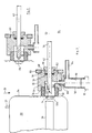
- FIG. 2 shows the detail II of FIG. 1 in a larger representation, with individual parts being shown in section.
- the removal head 32 has a cylindrical shape and is provided in its interior with a cylindrical cavity 52 which is arranged coaxially with the longitudinal axis 50 of the removal head and whose inside width is approximately equal to half the outer diameter of the removal head 32. Starting in the end face 54 of the removal head, the cavity extends in the axial direction approximately up to half the length of the removal head.
- the longitudinal axis 50 is approximately perpendicular to the cylindrical capsule 34.
- the cavity 52 is provided with a step 56 which widens the cavity, an elastic seal 58, preferably made of oil-resistant rubber, being inserted into the enlarged part of the cavity, and the seal 58 being inserted up to step 56.
- the step 56 has at least one annular projection for better sealing, which is pressed into the seal. This is not shown in Fig. 2.
- the seal 58 is annular, so that the cavity 52 also extends through the seal 58 with a constant light width.
- the seal 58 projects approximately as far out of the removal head in the axial direction from the end face 54 as is required for a secure sealing effect when the removal head 32 is pressed onto the compressor 20.
- the seal preferably protrudes approximately 1 to 3 times its wall thickness out of the removal head. That area of the seal that is in the expanded area of the cavity 52 has an axial length of approximately 1 to 3 times the wall thickness of the seal.
- a stuffing box 66 is provided, which is screwed into the removal head 66 from the rear 68 of the removal head and surrounds the drill rod 62 and onto one between the stuffing box 66 and the bottom of the gland bore arranged ring seal 70 acts.
- the stuffing box additionally prevents the boring bar from being pressed out of the removal head 32 in the axial direction in the event of excess pressure in the cavity 52.
- This stop expediently consists of a ring fastened to the boring bar or of a pin which penetrates the boring bar transversely and projects beyond the profile of the boring bar.
- the 2 consists of a solid, round metal rod, one end region 72 of which is arranged in the cavity 52 and, as the drilling tool, has a cutting surface 74 which extends at an acute angle ⁇ to the longitudinal axis 50.
- the other end region 76 of the boring bar 62 protrudes from the rear 68 of the removal head.
- the total length of the boring bar 62 is selected so that even when the cutting surface 74 penetrates into the capsule 34 of the compressor 20, a sufficiently long piece of the end region 76 still protrudes from the rear side 68 of the removal head.
- the length of this protruding piece is preferably approximately 5 to 10 times the diameter of the boring bar 62. A distance suitable for the easy drainage of the lubricating oil is maintained between the boring bar and the cylindrical wall of the cavity 52.
- the back of the removal head 68 is provided with a coaxial, annular shoulder 78 which runs at a distance from the stuffing box 66.
- the yoke 80 which extends transversely, preferably perpendicularly to the longitudinal axis 50, is loosely mounted on this shoulder 78, to which the ends of the tensioning strap 36 are fastened.
- the removal head 32 is provided with a removal opening 82 leading radially outward from the cavity 52 through the wall of the cavity and advantageously downward in FIG. 2, to which the solids separator 38 is connected outside the removal head.
- the removal opening has a clear width which is suitable for a quick removal of the lubricating oil.
- the solids separator 38 is designed as a closed hollow cylinder, one end face 86 of which has a central threaded connector 88 which is screwed into the removal opening 82, so that the cylindrical one Interior 90 of the solids separator 38 is connected to the cavity 52.
- a plug 92 is screwed in there.
- the sealing plug 92 is made of magnetic material, so that metal parts introduced into the interior 90 are held by the sealing plug 92.
- a radially outwardly leading outlet connector 94 is connected to the interior 90.
- the extraction line 40 shown in FIG. 1 is connected to this outlet connection by means of easily detachable pipe screw connections not shown in the figures.
- Fig. 3 shows a variant of the object of Fig. 2.
- the drill rod 61 is designed here as a twist drill, the cutting edges are located in the cavity 52 and the shaft is mounted in the removal head and from the Back 68 protrudes.
- the explanations given for the boring bar according to FIG. 2 also apply here.
- FIG. 4 shows a view of the compressor together with the removal device from the direction IV of FIG. 2 in a simplified and reduced representation.
- the cylindrical compressor 20 with a standing longitudinal axis, around whose capsule 34 the easily bendable, thin steel tension band 36 is looped.
- the rod-shaped yoke 80 can be seen, which preferably consists of a flat steel.
- a bore 96 is provided in the axial center of the yoke 80, with the aid of which the yoke 80 is mounted on the shoulder 78 of the removal head so that it can be removed easily, that is to say with play.
- the tensioning band is attached in a suitable manner, advantageously by means of a hinge
- the tensioning band is connected to the yoke with the interposition of a tensioning device 98.
- the tensioning device shown in FIG. 4 has a grub screw 100 fastened to the tensioning strap 36, which is guided through an opening of the yoke 80 and can be pulled through the yoke by an indicated threaded nut 102, so that the tensioning strap 36 is tensioned and the removal head 32 with inserted seal 58 presses against the capsule 34 of the compressor 20.
- the yoke has a length; which is at least the same as the thickness of the refrigerant compressor 20.
- the cooling device Before removing the lubricating oil and refrigerant, the cooling device is brought into the normal operating position, in which the refrigerant compressor is at the bottom, so that the lubricating oil collects in the refrigerant compressor.
- the removal device 32 with the end face 54 provided with the seal is pushed against the vertical, cylindrical capsule 34 of the compressor in the lower region and the yoke 80 is applied to the rear side of the removal head.
- the clamping band 36 is placed around the capsule 34 and tightened by the threaded nut 102 in such a way that the removal head 32 or its seal 58 is pressed completely tight against the capsule 34 of the compressor 20.
- the extraction nozzle 94 is connected to the refrigerant collecting container 44 by the connecting line 40, which is explained in more detail in FIG. 1, together with the components arranged therein.
- the shut-off elements 46, 48 are then opened.
- Remnants of lubricating oil that could still be located in the compressor 20 below the opening 104 are removed by tilting the cooling device backwards and thus allowing the lubricating oil to flow to the opening 104.
- the cooling device is conveniently on a work table.
- the pump 42 remains in operation until a certain vacuum has formed in the cooling system and thus there is a guarantee that the cooling system is practically free of the gaseous refrigerant.
- the shut-off element 46 of the refrigerant collecting container 44 is closed, the pump 42 is taken out of operation and the removal head together with the tightening strap are removed from the compressor 20.
- the shut-off device 48 is closed beforehand.
- the cooling system of the cooling device is now practically free of refrigerant and lubricating oil containing refrigerant, so that the cooling device can be easily scrapped.
- the removal head 32 has a boring bar 61 in the form of a twist drill
- a hand drill is connected to the shaft of the twist drill to insert the opening 104 into the capsule 34 of the refrigerant compressor and a hole is drilled in the capsule 34.
- the twist drill is then withdrawn until the opening 104 is exposed. For the rest, the disposal proceeds here as described above.
- the opening 104 must have a clear width which is suitable for the easy drainage of the lubricating oil. Therefore, the boring bars 61 and 62 must be suitable for making an opening of at least 6 mm inside width.
- the diameter of the drilling tool of the boring bar is preferably 8 to 15 mm.
- the solids separator 38 has an axial length of approximately 4 to 15 cm with a light width of 2 to 4 cm. The front and back of the removal head are perpendicular to the longitudinal axis 50.
Landscapes
- Engineering & Computer Science (AREA)
- General Engineering & Computer Science (AREA)
- Mechanical Engineering (AREA)
- Environmental & Geological Engineering (AREA)
- Physics & Mathematics (AREA)
- Thermal Sciences (AREA)
- Compressor (AREA)
- Separation By Low-Temperature Treatments (AREA)
- Electrical Discharge Machining, Electrochemical Machining, And Combined Machining (AREA)
- Processing Of Solid Wastes (AREA)
- Heat Treatments In General, Especially Conveying And Cooling (AREA)
Description
- Die Erfindung betrifft ein Verfahren zum umweltfreundlichen Entsorgen eines einen Kältemittelverdichter aufweisenden, geschlossenen Kühlsystems eines Kühlgerätes.
- Die Entsorgung von ausgedienten Kühlgeräten der genannten Art, insbesondere Kühl- und/oder Gefrierschränken aus dem Haushalts-oder Gewerbebereich, bedarf besonderer Sorgfalt. Während die festen Gehäusebestandteile der Kühlgeräte ohne weiteres verschrottet werden können, ist eine umweltfreundliche Entsorgung des Kühlsystems weit schwieriger und aufwendiger. Denn das im Kühlsystem enthaltene Kältemittel, meist auf der Basis von fluorierten Chlorkohlenwasserstoffen, soll aus Gründen des Umweltschutzes nicht in die Umgebung und die Atmosphäre gelangen. Um dies zu vermeiden, ist es aus dem internen Stand der Technik bekannt, einen mit einer Längsbohrung versehenen Dorn in die vom Kältemittelverdichter oben abgehende Kältemittel-Druckleitung des Kühlsystems einzudrücken und das gasförmige Kältemittel in einen geschlossenen Sammelbehälter, erforderlichenfalls unter Zwischenschaltung eines Verdichters, einzubringen. Hierbei bleibt das zusammen mit dem Kältemittel während der Herstellung des Kühlgerätes in das Kühlsystem eingebrachte Schmieröl im Kühlsystem, vorzugsweise an dessen tiefstem Bereich zurück. Da das Kältemittel weitgehend mit dem Schmieröl mischbar oder in diesem lösbar ist, verbleibt ein großer Teil des Kältemittels, ungefähr 20 bis 60%, im Schmieröl zurück und wird bei einem Anstieg der Kühlsystemtemperatur infolge eines Anstiegs der Umgebungstemperatur aus dem Schmieröl ausgetrieben, so daß es zu einer Umweltbelastung kommen kann.
- Der Erfindung liegt daher die Aufgabe zugrunde, ein Verfahren der eingangs genannten Art unter Überwindung der Nachteile des Standes der Technik derart weiterzubilden, daß das im Kühlsystem enthaltene Schmieröl auf einfache Weise und insbesondere zusammen mit dem gasförmigen Kältemittel aus dem Kühlsystem entfernt werden kann. Zusätzlich soll das Verfahren ohne Schwierigkeiten auf Kühlgeräte der verschiedensten Bauart anwendbar sein. Darüber hinaus soll eine Vorrichtung angegeben werden, die bei einfachem Aufbau für die Durchführung des Verfahrens besonders geeignet ist.
- Diese Aufgabe wird mit einem Verfahren mit den Merkmalen des Anspruches 1 gelöst.
- Es wird also unter Abschirmung gegenüber der Umgebung in jenem Bereich des Kühlsystems eine Öffnung eingebracht, in dem sich das Schmieröl ansammelt. Üblicherweise ist dies der tiefste Punkt des Kühlsystems bei der jeweiligen Aufstellung des Kühlgerätes. Durch entsprechende Aufstellung des Kühlgerätes vor der Entsorgung wie normale Arbeitsstellung, Seitenlage oder Kopflage wird zweckmäßig der Bereich der Schmierölansammlung festgelegt. Vorteilhaft werden solche Bereiche gewählt, an denen Abdichtmaßnahmen gegen den Übertritt von Schmieröl und/oder Kältemittel in die Umgebung leicht durchgeführt werden können. Empfehlenswert sind Bereiche mit nach Möglichkeit ausreichend großen ebenen oder gewölbten Außenflächen. Durch die eingebrachte Öffnung wird zunächst das Schmieröl und dann das gasförmige Kältemittel dem Kühlsystem entnommen und unter Abschirmung gegen die Umgebung dem Kältemittel-Sammelbehälter zugeführt und dort zwischengelagert. Die Öffnung besitzt zweckmäßig eine lichte Weite, die einen schnellen und leichten Abfluß des Schmiermittels gewährleistet. Der Fluß des Schmieröls wird hierbei durch den auf ihm lastenden Druck des gasförmigen Kältemittels des Kühlsystems gesteigert. Gegebenenfalls wird eine geeignete Pumpe eingeschaltet, die das Schmieröl zusammen mit dem gasförmigen Kältemittel weitestgehend aus dem Kühlsystem absaugt und in dem Sammelbehälter fördert. Nach diesem Vorgang ist es nicht erforderlich, das Kühlsystem wieder zu verschließen, da es praktisch frei ist von umweltbelastenden Medien. Auch läßt sich jetzt das Kühlsystem ohne weiteres verschrotten. Das im Sammelbehälter unter Verschluß gehaltene Schmieröl-Kältemittel wird dann an den Kältemittelhersteller zurückgegeben, der dieses aufarbeitet.
- Ist das Verfahren für die Entsorgung eines Kühlsystems vorgesehen, in dessen tiefsten Bereich ein gekapselter Verdichter angeordnet ist, so besteht eine besonders bevorzugte Weiterbildung der Erfindung darin, daß die Öffnung während einer Aufstellung des Kühlgerätes, die der Betriebsstellung gleich ist, im Bereich der schmierölansammlung des Verdichters in die Kapsel eingebracht wird. Dies ist besonders günstig, da an der Kapsel des Verdichters Dichtmaßnahmen gegen den Übertritt von Schmieröl oder gasförmigen Kältemittel in die Umgebung leicht durchgeführt werden können. Hierbei ist es für eine vollständige Entleerung besonders günstig, wenn die Öffnung im tiefsten Bereich der schmierölansammlung eingebracht wird.
- Eine Vorrichtung zur Entnahme des Inhalts aus einem innendruckbelasteten Bauteil durch Einbringen einer Öffnung in die Wandung des Bauteils, ohne daß der Inhalt des Bauteils unkontrolliert in die Umgebungsluft entweichen kann, ist bekanntgeworden durch die US-A1-30 45 511. Es handelt sich bei der bekannten Vorrichtung im wesentlichen um einen Entnahmekopf, der eine mit einer Dichtung versehene stirnseite, in welche ein Hohlraum mündet, aufweist und mittels einer Klammer an das innendruckbelastete Bauteil, nämlich ein Gasrohr,angepreßt ist. In dem Hohlraum ist eine in Längsrichtung bewegliche Bohrstange angeordnet, die mit einem Ende-den Entnahmekopf auf der der Stirnseite gegenüberliegenden Seite durchgreift, wobei sie mittels Dichtungen gasdicht gelagert ist. Das im Hohlraum befindliche Ende der Bohrstange ist als Rohrwerkzeug ausgebildet, das heißt mit zwei angeschliffenen schneiden entsprechend handelsüblichen Spiralbohrern.
- Am anderen Ende der Bohrstange ist ein Außengewinde eingeformt, das mit dem Entnahmekopf zusammennarbeitet und durch Drehung der Bohrstange den Vortrieb auf die Wandung des Bauteils zu bewirkt. Gleichzeitig arbeitet sich die am Ende der rohrstange befindlichen Schneiden in die Wandung ein und tragen dies örtlich durch Spanbildung ab, bis schließlich die Entnahmeöffnung hergestellt ist
- Von Nachteil ist die bekannte Vorrichtung hinsichtlich der durch die Gewindelänge begrenzten Eindringtiefe der Bohrstange sowie durch die erforderliche wiederkehrende Bearbeitung (schleifen) der schneiden. schließlich ist die bekannte Vorrichtung auf die Entleerung von Gasrohren mit kleinen Durchmessern zugeschnitten.
- Eine Verwendung zur Entleerung von Kühlsystemen, bei denen flüssiges Schmieröl und Kältemittel austreten, ist weder vorgesehen noch ohne weiteres möglich.
- Gemäß der Weiterbildung der Erfindung nach Anspruch 4 soll eine einfache, schnelle aber sichere Entleerung von Kühlsystemen von Kühlgeräten mittels einer speziellen Entnachmevorrichtung ermöglicht, werden.
- Danach ist vorgesehen, daß der Entnahmekopf an die Kapsel des Verdichters des Kühlsystems angesetzt wird und daß die Bohrstange, deren im Hohlraum befindliches Ende eine über den gesamten Querschnitt im Winkel von 20 bis 45° zur Längsachse verlaufende schneide aufweist, mittels schlag auf das aus dem Entnahmekopf ragende Ende in die Kapsel eindringt.
- Durch diese Vorrichtung ist sowohl das Einbringen der Öffnung in das Kühlsystem als auch die Entnahme des Schmieröls und des Kältemittels sehr einfach und schnell durchzuführen, wobei der Entnahmekopf für das Andrücken an geeignet große Flächen konzipiert ist.
- Eine zweckmäßige Weiterbildung der Erfindung besteht darin, daß als Klammer ein mit Joch und Spannvorrichtung verbundenes Spannband vorgesehen ist, das um die die Schmierölansammlung Kapsel des Verdichters des Kühlsystems gelegt ist. Mit Hilfe dieses Spannbandes wird die Stirnseite des Entnahmekopfes auf einfache Weise am Kühlsystem befestigt und gegen dieses gedrückt, so daß das Einbringen der Öffnung in das Kühlsystem und der Abfluß seines Inhalts unter absolutem Abschluß gegenüber der Umgebung verläuft.
- Zur weiteren Vereinfachung des Anpressens des Entnahmekopfes an das Kühlsystem ist es zweckmäßig, daß das Spannband an den Enden des Joches unter Zwischenschaltung der Spannvorrichtung festlegbar ist, wobei das Joch an der Rückseite des Entnahmekopfes gelagert ist.
- Für eine einfache Herstellung des Entnahmekopfes und dessen dichtes Anpressen an das Kühlsystem ist es am günstigsten, daß der Entnahmekopf und der koaxial in ihm angeordnete Hohlraum zylindrische Form aufweisen.
- Vorteilhaft ist die Bohrstange koaxial zum Hohlraum angeordnet, wobei der Hohlraum einen größeren Querschnitt als die Bohrstange aufweist. Unter dem Begriff Bohrstange im sinne vorliegender Erfindung soll jedes stangenförmige Gerät verstanden sein, das geeignet ist, eine Öffnung in das Kühlsystem einzubringen, durch die das Schmieröl und das gasförmige Kältemittel leicht austreten kann.
- Da bei der Einbringung der Öffnung in das Kühlsystem Späne anfallen können, ist es zweckmäßig, an die Austrittsöffnung einen Feststoffabscheider anzuschließen. In diesem Feststoffabscheider werden Späne oder andere vom Schmieröl und(oder Kältemittel mitgeführte Feststoffe zurückgehalten, so daß eine Verstopfung der zum Kältemittel-sammelbehälter führenden Verbindungsleitung vermieden ist.
- Weitere Vorteile und Merkmale der Erfindung gehen aus der folgenden Beschreibung von Ausführungsbeispielen im Zusammenhang mit den schematischen Zeichnungen hervor.
- Hierbei zeigt:
- Fig. 1 die teilweise aufgebrochene Seitenansicht eines Kühlgeräts, dessen Kältemittelverdichter zur Entsorgung mit dem Kältemittel-Sammelbehälter verbunden ist,
- Fig. 2 den Bereich II der Fig. 1 in größerer Darstellung und teilweise im axialen Vertikalschnitt,
- Fig. 3 den Entnahmekopf gemäß Fig. 2 als Ausführungsvariante und
- Fig. 4 eine Ansicht des Gegenstands der Fig. 2 aus der Richtung IV in verkleinerter und stark vereinfachter Darstellung.
- In Fig. 1 ist ein Kühlgerät 10 in Form eines Kühlschrankes in Seitenansicht und in normaler Aufstellungslage gezeigt, auf dessen Vorderseite eine Kühlschrank-Tür 12 und auf dessen Rückseite 14 der Kondensator 16 des Kühlsystems angedeutet ist. In einer zur Rückseite 14 offenen, unteren Nische 18 des Kühlgeräts ist im geodätisch tiefsten Bereich der gekapselte Kältemittelverdichter 20 angeordnet, der durch eine Druckleitung 22 mit dem Kondensator 16 und durch eine Saugleitung 24 mit dem im Kühlgerät angeordneten Verdampfer 26 verbunden ist. Beide Leitungen 22 und 24 gehen vom oberen Bereich des Kältemittelverdichters aus. Der Kältemittelverdichter 20, die Druckleitung 22, der Kondensator 16, die den Kondensator mit dem Verdampfer 26 verbindende Drosselleitung 28, der Verdampfer 26 sowie die Saugleitung 24 bilden im wesentlichen das Kühlsystem 30 im Sinne vorliegender Erfindung.
- Für die Entfernung des Kältemittels und des Schmieröls aus dem Kühlsystem ist der Entnahmekopf 32 an die in der Zeichnung vertikale Außenwand der Kapsel 34 des Kältemittelverdichters im unteren Bereich angepreßt. Die Anpressung erfolgt hierbei durch ein um die Kapsel 34 geschlungenes, stählernes Spannband 36. Wie aus Fig. 4 ersichtlich ist, hat die Kapsel 34 einen kreisförmigen Umriß.
- An den sich im Innern des Entnahmekopfes 32 befindenden und in Fig. 1 nicht eingezeichneten Hohlraum ist ein sich im Außenraum 64 befindender und nach unten zeigender Feststoffabscheider 38 angeschlossen. Der Feststoffabscheider ist durch eine Verbindungsleitung 40 mit eingefügter Schmieröl- und Kältemittel-Pumpe 42 mit dem mit einem Absperrorgan 46 versehenen druckfesten Kältemittel-Sammelbehälter 44 verbunden. Stromauf der Pumpe 42 ist noch ein Absperrorgan 48 in die Verbindungsleitung 40 eingefügt. Die Verbindungsleitung 40 hat eine für den Abfluß des Schmieröls geeignete lichte Weite.
- Fig. 2 zeigt die Einzelheit II der Fig. 1 in größerer Darstellung, wobei einzelne Teile im Schnitt dargestellt sind. Man erkennt den Kältemittelverdichter 20 sowie das um den Kältemittelverdichter geschlungene Spannband 36 sowie den Entnahmekopf 32.
- Der Entnahmekopf 32 weist eine zylindrische Form auf und ist in seinem Innenraum mit einem zur Längsachse 50 des Entnahmekopfes koaxial angeordneten, zylindrischen Hohlraum 52 versehen, dessen lichte Weite ungefähr dem halben Außendurchmesser des Entnahmekopfes 32 gleich ist. In axialer Richtung erstreckt sich der Hohlraum, ausgehend von der Stirnseite 54 des Entnahmekopfes, ungefähr bis zur halben Länge des Entnahmekopfes. Die Längsachse 50 steht ungefähr senkrecht auf der zylindrischen Kapsel 34.
- Im Bereich der Stirnseite 54 ist der Hohlraum 52 mit einer den Hohlraum erweiternden Stufe 56 versehen, wobei in den erweiterten Teil des Hohlraums eine elastische Dichtung 58, vorzugsweise aus ölfestem Gummi, eingesetzt ist, und wobei die Dichtung 58 bis zur Stufe 56 eingeführt ist. Die Stufe 56 weist zur besseren Abdichtung wenigstens einen ringförmigen Vorsprung auf, der sich in die Dichtung eindrückt. Dies ist in Fig. 2 nicht dargestellt.
- Die Dichtung 58 ist ringförmig ausgebildet, so daß sich der Hohlraum 52 mit gleichbleibender Lichtweite auch durch die Dichtung 58 erstreckt. Die Dichtung 58 ragt ungefähr so weit aus dem Entnahmekopf in axialer Richtung aus der Stirnseite 54 heraus, wie es für eine sichere Dichtwirkung beim Anpressen des Entnahmekopfes 32 an den Verdichter 20 erforderlich ist. Vorzugsweise ragt die Dichtung ungefähr das 1 bis 3-fache ihrer Wandstärke aus dem Entnahmekopf heraus. Jener Bereich der Dichtung, der sich im erweiterten Bereich des Hohlraumes 52 befindet, hat eine axiale Länge von ungefähr dem 1 bis 3-fachen der Wandstärke der Dichtung.
- In jenem axialen Bereich des Entnahmekopfes 32, in den sich der Hohlraum 52 nicht erstreckt, ist eine koaxiale Bohrung, angebracht, in der eine Bohrstange 62 von kreisförmigem Querschnitt in axialer Richtung bewegbar und um die Längsachse 50 drehbar gelagert ist. Um einen Übertritt von Schmieröl und/oder Kältemittel vom Hohlraum 52 in den Außenraum 64 zu verhindern, ist eine Stopfbüchse 66 vorgesehen, die von der Rückseite 68 des Entnahmekopfes her in den Entnahmekopf 66 eingeschraubt ist und die Bohrstange 62 umgibt und auf eine zwischen der Stopfbüchse 66 und dem Grund der Stopfbüchsenbohrung angeordnete Ringdichtung 70 einwirkt. Durch die Stopfbüchse wird zusätzlich verhindert, daß bei Überdruck im Hohlraum 52 die Bohrstange in axialer Richtung aus dem Entnahmekopf 32 gedrückt wird. Vorteilhaft ist es, die Bohrstange innerhalb des Hohlraumes 52 mit einem Anschlag zu versehen, der ein Herausdrücken der Bohrstange verhindert. Dieser Anschlag besteht zweckmäßig aus einem auf der Bohrstange befestigten Ring oder aus einem die Bohrstange quer durchdringenden und über das Profil der Bohrstange ragenden Stift.
- Die Bohrstange 62 gemäß Fig. 2 besteht aus einem massivem, runden Metallstab, dessen einer Endbereich 72 im Hohlraum 52 angeordnet ist und als Bohrwerkzeug eine unter einem spitzen Winkel α zur Längsachse 50 verlaufende Schneidfläche 74 aufweist. Der andere Endbereich 76 der Bohrstange 62 ragt aus der Rückseite 68 des Entnahmekopfes heraus. Die Gesamtlänge der Bohrstange 62 ist so gewählt, daß selbst beim Eindringen der Schneidfläche 74 in die Kapsel 34 des Verdichters 20 ein ausreichend langes Stück des Endbereiches 76 noch aus der Rückseite 68 des Entnahmekopfes herausragt. Vorzugsweise ist die Länge dieses herausragenden Stückes ungefähr das 5 bis 10-fache des Durchmessers der Bohrstange 62. Zwischen der Bohrstange und der zylindrischen Wand des Hohlraumes 52 ist ein für den leichten Abfluß des Schmieröls geeigneter Abstand eingehalten.
- Die Rückseite des Entnahmekopfes 68 ist mit einem koaxialen, ringförmigen Absatz 78 versehen, der mit Abstand zur Stopfbüchse 66 verläuft. An diesem Absatz 78 ist das quer, vorzugsweise senkrecht zur Längsachse 50 verlaufende Joch 80 lose gelagert, an dem die Enden des Spannbandes 36 befestigt sind.
- Der Entnahmekopf 32 ist mit einer vom Hohlraum 52 durch die Wand des Hohlraums radial nach außen und in Fig. 2 vorteilhaft nach unten führenden Entnahmeöffnung 82 versehen, an die der Feststoffabscheider 38 außerhalb des Entnahmekopfes angeschlossen ist. Die Entnahmeöffnung hat eine für eine schnelle Abfuhr des Schmieröls geeignete lichte Weite.
- Der Feststoffabscheider 38 ist als geschlossener Hohlzylinder ausgebildet, dessen eine Stirnfläche 86 einen zentrischen Gewindestutzen 88 aufweist, der in die Entnahmeöffnung 82 eingeschraubt ist, so daß der zylindrische Innenraum 90 des Feststoffabscheiders 38 mit dem Hohlraum 52 verbunden ist. Zum Verschluß der anderen Stirnseite des Feststoffabscheiders ist ein Verschlußstopfen 92 dort eingeschraubt. Der Verschlußstopfen 92 besteht aus magnetischem Material, so daß in den Innenraum 90 eingeschleppte Metallteile vom Verschlußstopfen 92 festgehalten werden. In der Nähe des Gewindestutzens 88 ist ein radial nach außen führender Auslaßstutzen 94 an den Innenraum 90 angeschlossen. An diesen Auslaßstutzen ist die in Fig. 1 gezeigte Entnahmeleitung 40 durch in den Figuren nicht dargestellte, leicht lösbare Rohrverschraubungen angeschlossen.
- Fig. 3 zeigt eine Ausführungsvariante des Gegenstands der Fig. 2. Der einzige Unterschied gegenüber Fig. 2 besteht darin, daß die Bohrstange 61 hier als Spiralbohrer ausgebildet ist, dessen Schneidkanten sich im Hohlraum 52 befinden und dessen Schaft im Entnahmekopf gelagert ist und aus der Rückseite 68 herausragt. Bezüglich der Länge und Abdichtung des Spiralbohrers gelten auch hier die zur Bohrstange gemäß Fig. 2 gegebenen Erläuterungen.
- Fig. 4 zeigt eine Ansicht des Verdichters samt Entnahmevorrichtung aus der Richtung IV der Fig. 2 in vereinfachter und verkleinerter Darstellung. Man erkennt den zylinderförmigen Verdichter 20 mit stehender Längsachse, um dessen Kapsel 34 das leicht biegbare, dünne stählerne Spannband 36 geschlungen ist. Ferner erkennt man das stabförmige Joch 80, das vorzugsweise aus einem Flachstahl besteht. In der axialen Mitte des Joches 80 ist eine Bohrung 96 vorgesehen, mit deren Hilfe das Joch 80 auf den Absatz 78 des Entnahmekopfes leicht entfernbar, das heißt mit Spiel, gelagert ist. Am in Fig. 4 unteren Endbereich des Joches 80 ist das Spannband auf geeignete Weise, vorteilhaft durch ein Scharnier, befestigt, woge gen am entgegengesetzten Endbereich des Joches 80 das Spannband unter Zwischenschaltung einer Spannvorrichtung 98 mit dem Joch verbunden ist. Die in Fig. 4 gezeigte Spannvorrichtung weist einen am Spannband 36 befestigten Gewindestift 100 auf, der durch eine Öffnung des Joches 80 geführt ist und durch eine angedeutete Gewindemutter 102 durch das Joch ziehbar ist, so daß das Spannband 36 angespannt wird und den Entnahmekopf 32 mit eingefügter Dichtung 58 gegen die Kapsel 34 des Verdichters 20 drückt. Das Joch hat eine Länge; die mindestens der Dicke des Kältemittelverdichters 20 gleich ist.
- Vor der Entfernung des Schmieröls und Kältemittels wird das Kühlgerät in normale Betriebsstellung gebracht, in der der Kältemittelverdichter unten ist, so daß sich das Schmieröl im Kältemittelverdichter sammelt. Zur Entfernung des Schmieröls und des Kältemittels aus dem Kühlsystem 30 wird die Entnahmevorrichtung 32 mit der mit der Dichtung versehenen Stirnseite 54 gegen die vertikale, zylindrische Kapsel 34 des Verdichters im unteren Bereich angestoßen und das Joch 80 auf die Rückseite des Entnahmekopfes aufgebracht. Jetzt wird das Spannband 36 um die Kapsel 34 gelegt und durch die Gewindemutter 102 derart angespannt, daß der Entnahmekopf 32 bzw. dessen Dichtung 58 vollkommen dicht gegen die Kapsel 34 des Verdichters 20 gepreßt wird. Jetzt wird der Entnahmestutzen 94 durch die in Fig. 1 näher erläuterten Verbindungsleitung 40 samt darin angeordneten Bauteilen mit dem Kältemittel-Sammelbehälter 44 verbunden. Anschließend werden die Absperrorgane 46,48 geöffnet.
- Anschließend wird durch einen Hammerschlag auf das sich im Außenraum befindende Ende der Bohrstange 62 diese in Richtung zur Kapsel 34 vorgetrieben, so daß die Schneidfläche 74 unter Einbringung einer Öffnung 104 in die Kapsel 34 eindringt. Jetzt wird die Bohrstange wieder in Richtung Außenraum so weit axial zurückgezogen, daß die in Fig. 2 und 3 angedeutete Öffnung 104 der Kapsel 34 frei ist und zunächst das Schmieröl aus dem Innenraum des Verdichters 20 in den Hohlraum 52 übertritt, von hier durch die Entnahmeöffnung 82 in den Feststoffabscheider 38 strömt, in dem mitgeführte Metallteile oder Metallspäne durch den magnetischen Verschlußstopfen 92 festgehalten und abgeschieden werden. Das solchermaßen grobgereinigte Schmieröl strömt dann durch den Auslaßstutzen 94 und die Verbindungsleitung 40 unter Mitwirkung der Pumpe 42 in den Kältemittel-Sammelbehälter 44. Nach dem Ende des Schmierölflusses strömt das gasförmige Kältemittel auf demselben Weg zum Kältemittel-Sammelbehälter 44.
- Reste von Schmieröl die sich im Verdichter 20 unterhalb der Öffnung 104 noch befinden könnten, werden dadurch entfernt, daß das Kühlgerät nach hinten geneigt wird und für das Schmieröl somit die Möglichkeit gegeben ist, zur Öffnung 104 zu fließen. Hierzu steht das Kühlgerät zweckmäßig auf einem Arbeitstisch.
- Die Pumpe 42 bleibt solange in Betrieb, bis sich im Kühlsystem ein gewisses Vakuum gebildet hat und somit Gewähr gegeben ist, daß das Kühlsystem praktisch frei ist vom gasförmigen Kältemittel. Jetzt wird das Absperrorgan 46 des Kältemittel-Sammelbehälters 44 geschlossen, die Pumpe 42 außer Betrieb genommen und der Entnahmekopf samt Spannband vom Verdichter 20 entfernt. Vorher wird das Absperrorgan 48 geschlossen.
- Das Kühlsystem des Kühlgerätes ist jetzt praktisch frei von Kältemittel und Kältemittel enthaltendem Schmieröl, so daß das Kühlgerät ohne weiteres verschrottet werden kann.
- Weist der Entnahmekopf 32 eine Bohrstange 61 in Form eines Spiralbohrers auf, so wird zum Einbringen der Öffnung 104 in die Kapsel 34 des Kältemittelverdichters an den Schaft des Spiralbohrers eine Handbohrmaschine angeschlossen und ein Loch in die Kapsel 34 gebohrt. Anschließend wird der Spiralbohrer so weit zurückgezogen, daß die Öffnung 104 freiliegt. Im übrigen verläuft auch hier die Entsorgung wie bereits weiter oben beschrieben wurde.
Die Öffnung 104 muß eine lichte Weite habe, die für den leichten Abfluß des Schmieröls geeignet ist. Daher muß die Bohrstange 61 und 62 für das Einbringen einer Öffnung von mindestens 6 mm lichter Weite geeignet sein. Vorzugsweise beträgt der Durchmesser des Bohwerkzeugs der Bohrstange 8 bis 15 mm.
Für die Dimensionierung des Entnahmekopfes gilt zweckmäßig folgendes:
Außendurchmesser 4 bis 8 cm, axiale Länge das 0,8 bis 1,5-fache des Außendurchmessers, die lichte Weite des Hohlraumes 52 beträgt das 0,5 bis 0,9-fache des Entnahmekopf-Außendurchmessers, die Tiefe des Hohlraumes 52 ist ungefähr das 0,4 bis 0,6-fache der Länge des Entnahmekopfes.
Der Feststoffabscheider 38 hat eine axiale Länge von ungefähr 4 bis 15 cm bei einer Lichtweite von 2 bis 4 cm.
Die Stirn- und Rückseite des Entnahmekopfes verlaufen senkrecht zur Längsachse 50.
Claims (6)
Priority Applications (1)
| Application Number | Priority Date | Filing Date | Title |
|---|---|---|---|
| AT89116742T ATE76959T1 (de) | 1988-09-17 | 1989-09-09 | Verfahren zum umweltfreundlichen entsorgen eines kuehlsystems. |
Applications Claiming Priority (2)
| Application Number | Priority Date | Filing Date | Title |
|---|---|---|---|
| DE3831693 | 1988-09-17 | ||
| DE3831693A DE3831693A1 (de) | 1988-09-17 | 1988-09-17 | Verfahren zum umweltfreundlichen entsorgen eines kuehlsystems sowie vorrichtung zur durchfuehrung des verfahrens |
Publications (3)
| Publication Number | Publication Date |
|---|---|
| EP0360113A2 EP0360113A2 (de) | 1990-03-28 |
| EP0360113A3 EP0360113A3 (en) | 1990-07-25 |
| EP0360113B1 true EP0360113B1 (de) | 1992-06-03 |
Family
ID=6363184
Family Applications (1)
| Application Number | Title | Priority Date | Filing Date |
|---|---|---|---|
| EP19890116742 Expired - Lifetime EP0360113B1 (de) | 1988-09-17 | 1989-09-09 | Verfahren zum umweltfreundlichen Entsorgen eines Kühlsystems |
Country Status (3)
| Country | Link |
|---|---|
| EP (1) | EP0360113B1 (de) |
| AT (1) | ATE76959T1 (de) |
| DE (2) | DE3831693A1 (de) |
Families Citing this family (6)
| Publication number | Priority date | Publication date | Assignee | Title |
|---|---|---|---|---|
| NL8902158A (nl) * | 1989-08-25 | 1991-03-18 | Geert Harmannus Leemput En Her | Inrichting voor het aftappen van fluidum door een wand. |
| NL8902218A (nl) * | 1989-09-04 | 1991-04-02 | Aviv V O F | Werkwijze en inrichting voor het ledigen van cfk houdende koelsystemen. |
| FR2696436B1 (fr) * | 1992-10-01 | 1995-01-06 | Armines | Procédé et dispositif de perforation d'un réservoir. |
| JPH11223425A (ja) * | 1998-02-10 | 1999-08-17 | Fujikoki Corp | 膨張弁 |
| GB9824798D0 (en) * | 1998-11-12 | 1999-01-06 | Ici Plc | Heat transfer device |
| CN113905848B (zh) * | 2019-07-04 | 2023-09-19 | 日商地球股份有限公司 | 加工冷却装置 |
Family Cites Families (13)
| Publication number | Priority date | Publication date | Assignee | Title |
|---|---|---|---|---|
| US2279636A (en) * | 1939-09-28 | 1942-04-14 | Mueller Co | Clamping belt for connecting tapping machines to mains |
| US2462535A (en) * | 1946-07-03 | 1949-02-22 | Gen Motors Corp | Refrigerating apparatus with charging plug |
| US3045511A (en) * | 1959-03-18 | 1962-07-24 | Dresser Ind | Service t |
| US3548861A (en) * | 1969-05-19 | 1970-12-22 | John W Mullins | Line tapping service valve |
| US3974846A (en) * | 1972-07-14 | 1976-08-17 | Samuel Serota | Apparatus and method for gaining access to the contents of pressurized vessels and systems |
| DE2648097C3 (de) * | 1976-10-23 | 1984-09-06 | Sihi Gmbh & Co Kg, 2210 Itzehoe | Vorrichtung zum Füllen und Dichtigkeitsprüfen von Flüssigkeitskreisläufen |
| DE2754348A1 (de) * | 1977-12-07 | 1979-06-13 | Juergen Berger | Oelablass- und -auffangvorrichtung |
| US4261178A (en) * | 1979-01-19 | 1981-04-14 | Robinair Manufacturing Corporation | Environmental protection refrigeration disposal and charging system |
| US4476688A (en) * | 1983-02-18 | 1984-10-16 | Goddard Lawrence A | Refrigerant recovery and purification system |
| DE3338159C2 (de) * | 1983-10-20 | 1986-01-16 | Danfoss A/S, Nordborg | Ventilvorrichtung zum Evakuieren und/oder Füllen eines Kältesystems |
| US4535802A (en) * | 1984-01-26 | 1985-08-20 | Robertson James D | Twist-cam refrigerant dispensing valve |
| US4698983A (en) * | 1986-06-11 | 1987-10-13 | Ruben Hechavarria | Modified compressor unit |
| DE3728174A1 (de) * | 1987-08-24 | 1989-03-09 | Reinhold Holstein | Kaeltemittel- & oel-entsorgungs-station fuer kuehlgeraete, klimaanlagen u. a. |
-
1988
- 1988-09-17 DE DE3831693A patent/DE3831693A1/de not_active Withdrawn
-
1989
- 1989-09-09 DE DE8989116742T patent/DE58901588D1/de not_active Expired - Fee Related
- 1989-09-09 AT AT89116742T patent/ATE76959T1/de not_active IP Right Cessation
- 1989-09-09 EP EP19890116742 patent/EP0360113B1/de not_active Expired - Lifetime
Also Published As
| Publication number | Publication date |
|---|---|
| DE3831693A1 (de) | 1990-03-22 |
| EP0360113A3 (en) | 1990-07-25 |
| EP0360113A2 (de) | 1990-03-28 |
| ATE76959T1 (de) | 1992-06-15 |
| DE58901588D1 (de) | 1992-07-09 |
Similar Documents
| Publication | Publication Date | Title |
|---|---|---|
| DE3780967T2 (de) | Verfahren und vorrichtung zur montage eines sensors oder stopfens in eine fluessigkeitsfuehrende leitung. | |
| EP1934404B1 (de) | Reibrohranker und inflationsadapter für diesen | |
| WO2000021875A1 (de) | Abdichtvorrichtung | |
| CH683122A5 (de) | Ersatzrohr, Verfahren und Vorrichtung zur Einführung eines Ersatzrohres in eine bestehende Rohrleitung. | |
| DE60317550T2 (de) | Vorrichtung zur filtrierung von bohrschlamm | |
| DE102004048002B3 (de) | Abdichtvorrichtung | |
| EP0360113B1 (de) | Verfahren zum umweltfreundlichen Entsorgen eines Kühlsystems | |
| DE2030673B2 (de) | Vorrichtung zum Einbringen eines Zusatzmittels in ein strömendes Fluid, insbesondere Schmiervorrichtung | |
| DE2838186C2 (de) | Vorrichtung zum Verpressen von Injiziergut | |
| DE3129870A1 (de) | Verfahren zum instandsetzen von im erdreich verlegten rohrleitungssystemen und vorrichtung zur durchfuehrung des verfahrens | |
| DE4000172A1 (de) | Vorrichtung zum gasdichten absaugen | |
| DE2059905C2 (de) | Verfahren und Vorrichtung zum Absperren des Strömungswegs in einer unter Druck stehenden Rohrleitung | |
| DE3501215C2 (de) | ||
| EP3444179B1 (de) | Zugangsvorrichtung für einen fluidtank | |
| DE69407172T2 (de) | Herstellung von gewindebohrungen | |
| DE3546802C2 (de) | Verfahren zum Errichten eines Umganges und zur späteren Entfernung des Umganges bei einem Gasleitungsrohr aus Kunststoff | |
| EP2381153A1 (de) | Verfahren und Vorrichtung für das Trennen und Verschließen von unter Druck stehenden Gasleitungen | |
| DE19802884C1 (de) | Anbohrarmatur mit Absperrfunktion für ein unter Mediendruck stehendes Hauptrohr | |
| DE69804266T2 (de) | Vorrichtung und Anlage zum Rückgewinnen von Brennstoff, enthalten in einem Fahrzeugtank mit einer Wand aus Kunststoffmaterial | |
| DE8907312U1 (de) | Anstechvorrichtung zum Anstechen einer Kühlflüssigkeitsleitung in einer zu entsorgenden Kühlvorrichtung | |
| DE102012108141B4 (de) | Werkzeug zum Abdichten von Rohren | |
| DE102011116953B4 (de) | Verfahren, Absperr- und Anschlussvorrichtungen zum Anbau in der Tiefsee zwecks Ausflussstoppen bzw. Anschließen an havarierten Erdgas- bzw. Erdölförderrohrstutzen, Präventer und Bohrgestänge | |
| DE102007043622B3 (de) | Verfahren und Vorrichtung zur Vorbereitung und Durchführung einer Bodenbehandlung | |
| DE3900123A1 (de) | Anstechvorrichtung zum anstechen einer kuehlfluessigkeitsleitung in einer zu entsorgenden kuehlvorrichtung | |
| DE69403727T2 (de) | Fräswerkzeug und Bohrvorrichtung, zum Anbohren von Röhren |
Legal Events
| Date | Code | Title | Description |
|---|---|---|---|
| PUAI | Public reference made under article 153(3) epc to a published international application that has entered the european phase |
Free format text: ORIGINAL CODE: 0009012 |
|
| AK | Designated contracting states |
Kind code of ref document: A2 Designated state(s): AT CH DE LI |
|
| PUAL | Search report despatched |
Free format text: ORIGINAL CODE: 0009013 |
|
| AK | Designated contracting states |
Kind code of ref document: A3 Designated state(s): AT CH DE LI |
|
| 17P | Request for examination filed |
Effective date: 19900810 |
|
| 17Q | First examination report despatched |
Effective date: 19910221 |
|
| GRAA | (expected) grant |
Free format text: ORIGINAL CODE: 0009210 |
|
| AK | Designated contracting states |
Kind code of ref document: B1 Designated state(s): AT CH DE LI |
|
| REF | Corresponds to: |
Ref document number: 76959 Country of ref document: AT Date of ref document: 19920615 Kind code of ref document: T |
|
| REF | Corresponds to: |
Ref document number: 58901588 Country of ref document: DE Date of ref document: 19920709 |
|
| RAP4 | Party data changed (patent owner data changed or rights of a patent transferred) |
Owner name: YORK INTERNATIONAL GMBH |
|
| REG | Reference to a national code |
Ref country code: CH Ref legal event code: PUE Owner name: YORK INTERNATIONAL GMBH |
|
| PGFP | Annual fee paid to national office [announced via postgrant information from national office to epo] |
Ref country code: CH Payment date: 19920903 Year of fee payment: 4 Ref country code: AT Payment date: 19920903 Year of fee payment: 4 |
|
| PGFP | Annual fee paid to national office [announced via postgrant information from national office to epo] |
Ref country code: DE Payment date: 19921015 Year of fee payment: 4 |
|
| PLBE | No opposition filed within time limit |
Free format text: ORIGINAL CODE: 0009261 |
|
| STAA | Information on the status of an ep patent application or granted ep patent |
Free format text: STATUS: NO OPPOSITION FILED WITHIN TIME LIMIT |
|
| 26N | No opposition filed | ||
| PG25 | Lapsed in a contracting state [announced via postgrant information from national office to epo] |
Ref country code: AT Effective date: 19930909 |
|
| PG25 | Lapsed in a contracting state [announced via postgrant information from national office to epo] |
Ref country code: LI Effective date: 19930930 Ref country code: CH Effective date: 19930930 |
|
| REG | Reference to a national code |
Ref country code: CH Ref legal event code: PL |
|
| PG25 | Lapsed in a contracting state [announced via postgrant information from national office to epo] |
Ref country code: DE Effective date: 19940601 |