EP0360187B1 - Dispositif de sécurité pour la fusée d'un projectile à rotation - Google Patents
Dispositif de sécurité pour la fusée d'un projectile à rotation Download PDFInfo
- Publication number
- EP0360187B1 EP0360187B1 EP89117207A EP89117207A EP0360187B1 EP 0360187 B1 EP0360187 B1 EP 0360187B1 EP 89117207 A EP89117207 A EP 89117207A EP 89117207 A EP89117207 A EP 89117207A EP 0360187 B1 EP0360187 B1 EP 0360187B1
- Authority
- EP
- European Patent Office
- Prior art keywords
- retaining ring
- rotor
- projectile
- groove
- radial
- Prior art date
- Legal status (The legal status is an assumption and is not a legal conclusion. Google has not performed a legal analysis and makes no representation as to the accuracy of the status listed.)
- Expired - Lifetime
Links
Images
Classifications
-
- F—MECHANICAL ENGINEERING; LIGHTING; HEATING; WEAPONS; BLASTING
- F42—AMMUNITION; BLASTING
- F42C—AMMUNITION FUZES; ARMING OR SAFETY MEANS THEREFOR
- F42C15/00—Arming-means in fuzes; Safety means for preventing premature detonation of fuzes or charges
- F42C15/20—Arming-means in fuzes; Safety means for preventing premature detonation of fuzes or charges wherein a securing-pin or latch is removed to arm the fuze, e.g. removed from the firing-pin
- F42C15/22—Arming-means in fuzes; Safety means for preventing premature detonation of fuzes or charges wherein a securing-pin or latch is removed to arm the fuze, e.g. removed from the firing-pin using centrifugal force
Definitions
- the invention relates to a safety device for a swirl projectile detonator according to the preamble of claim 1.
- Malfunctions can result from the uneven masses of the U-shaped retaining ring.
- the launch acceleration and the swirl can tilt the retaining ring during the return and opening stroke in the radial groove on the housing so that the legs prevent the rotor from absorbing the swirl necessary for the function.
- the retaining ring can jam in its rearward position due to an unintentional impact and lock the rotor securely. In both cases there are explosive duds after firing.
- a safety device for a swirl projectile detonator in which a corrugated retaining ring with a slot is divided into segments by incisions with deformable webs and therefore has approximately a groove profile.
- the segments lie alternately on the igniter housing and on the rotor.
- the object of the invention is to provide a rotor fuse for a swirl projectile detonator, which functions reliably when the swirl projectile is fired, by releasing the rotor and which ensures that the rotor is re-secured even after rough handling.
- Essential to the invention are the retaining ring which bears against the rotor without radial preload, the ease of installation of the retaining ring on the rotor and the retaining ring which is axially freely movable in the space provided in the igniter housing due to the compression spring provided.
- the retaining ring has a small gap in the centripedal and centrifugal directions to the respective contact surfaces. This avoids material fatigue, as is the case, for example, with the retaining rings according to the prior art. Malfunctions in this regard cannot therefore occur.
- the retaining ring which can move freely axially against spring force, allows the rotor to be secured again, for example during drop tests or impact loads when handling a projectile.
- the invention provides the necessary functional reliability with regard to two trigger criteria, namely 1st backup when accelerating the storey and 2nd backup when swirling.
- the almost closed retaining ring supports the rotor in the radial direction on the igniter housing.
- the inertial forces of the rotor are derived from the retaining ring in the igniter housing.
- Adverse deformations of the retaining ring cannot occur due to its relatively high section modulus.
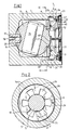
- a securing device 1 provides that a retaining ring 2 is centered on the one hand by a conical compression spring 3 in an annular groove 4 of a rotor 5, and on the other hand in the radial directions by the annular groove 4 and a wall 6 of an igniter housing 7 via annular gaps 8.
- the annular groove 4 has a bottom 10 and an end face 11.
- the rotor 5 has a detonator 15 and a fixing cone 16 for an axially movable securing sleeve 17 in a known manner.
- the igniter housing 7 supports the securing sleeve 17 and an ignition needle 18. Furthermore, the initiator housing 7 supports the rotor 5 already described via a spherical recess 20 a corresponding spherical recess 21 is provided in a charge housing 22. These recesses 20, 21 form a slide bearing for the rotor 5.
- the compression spring 3 fixes the rotor 5 in the recess 20 via the retaining ring 2. A further additional storage is not provided in a recess 8 of the igniter housing 7.
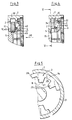
- the retaining ring 2 according to FIGS. 2 and 5 is provided with a keyway profile, as a result of which there are inner support tabs 25 with recesses 26 between them.
- the support tabs 25 have curved support surfaces 27 corresponding to the annular groove 4.
- a ring 28 carries the support tabs 25, the ring 28 being separated by a slot 29.
- the detonator housing 7 has a radial groove 30, the bottom 31 of which is deeper than the wall 6 of the detonator housing by the distance 32.
- the two end faces 33, 35 are so far apart that the retaining ring 2 can be accommodated with ample axial play.
- An inclined surface 34 optionally serves as an adjustment aid for the expanding retaining ring 2.
- a recess 40 with a peripheral edge 41 is provided on the charge housing 22 for receiving the base 48 of the compression spring 3. Furthermore, the charge housing 22 has an amplifier charge in a manner not shown.
- the compression spring 3 rests with its head portion 9 on a surface 12 of the retaining ring 2.
- the base 48 of the compression spring 3 is supported by the charge housing 22.
- the charge housing 22 is connected to the igniter housing 7 via a threaded connection 23.
- the securing device 1 of a swirl igniter (not shown further) reacts to the launch acceleration acting in the direction of arrow 50 by an axial stroke of the retaining ring 2 against the force 3.
- the compression spring 3 according to FIG. 3.
- the retaining ring 2 is in its outermost axial lifting position, since the compression spring 3 cannot be compressed any further. In this position, the retaining ring 2 is aligned with the radial groove 30.
- the retaining ring 2 can expand into the radial groove 30 according to FIG. 4 after a projectile has been swirled in the weapon barrel.
- the retaining ring 2 consists of a beryllium bronze. This material ensures that the retaining ring 2, due to the centrifugal forces acting mainly on the support tabs 25, lies completely against the bottom 31 of the radial groove 30.
- the webs 14 lying between the support tabs 25 are plastically, that is to say permanently, deformed.
- the rotor 5 released by the holding ring 2 aligns itself in the position shown in FIG. 4 due to its center of gravity, the securing sleeve 17 being pushed back by the fixing cone 16.
- the rotor 5 is locked in the focus shown in this figure by means not shown.
- the compression spring 3 puts the retaining ring 2 on the end face 33.
- the ignition needle 18 strikes the detonator 15 in a known manner. Its ignition energy then initiates a transfer charge. If a shock is exerted on the securing device 1 according to arrow 50 in FIG. 3 during a drop test or rough handling, the retaining ring 2 lifts off from the rotor 5 according to FIG. 3 and, however, becomes the one from FIG. 1 again after the shock Assume the visible position on the rotor 5. A possible axial offset of the bore diameter 45 to the diameter 46 of the annular groove 4 is avoided by the almost identical pin diameter 47 of the charge housing 22.
- the securing sleeve 17 ensures that the rotor 5 remains in the safe position according to FIG. 1 in the phase in which the retaining ring 2 is lifted off the rotor 5.
- the spring-loaded mounting of the rotor 5 by the compression spring 3 is also advantageous.
- the compression spring 3 creates a gap 49 in that the rotor 5 is pressed into the recess 20 in the igniter housing 7.
- the rotor 5 due to the compression spring 3 and the gap 49 to have a spring-damped positional offset within the recess 8.
- the ignition threshold of the detonator 15 in the case of shock loads is therefore considerably lower than in the case of detonators according to the prior art.
- Suitable materials for the retaining ring 2 are aluminum or steel.
- the required material properties are high breaking strength and high toughness.
Landscapes
- Engineering & Computer Science (AREA)
- General Engineering & Computer Science (AREA)
- Air Bags (AREA)
- Aiming, Guidance, Guns With A Light Source, Armor, Camouflage, And Targets (AREA)
Claims (3)
- Dispositif de sécurité (1), pour un allumeur de projectile à rotation, avec un corps d'allumeur (7) et un corps de palier (22), dans lequel un rotor (5) sphérique est monté, mobile en rotation, et dans lequel est ménagée une rainure radiale (30), le rotor (5) présentant un perçage avec un détonateur (15) inséré dedans et, sur une zone périphérique, une gorge annulaire (4), s'étendant dans un plan décalé axialement par rapport à la rainure radiale (30) et dans laquelle est insérée une bague de maintien (2), susceptible de s'ouvrir par écartement et libérant le rotor (5) maintenu en position de sécurité une fois le projectile tiré, en se déplaçant axialement et en s'agrandissant radialement, sous l'effet de forces axiales et de rotation, le rotor (5) pouvant après sa libération pivoter avec le détonateur (15) en position armée,
et la bague de maintien (2) présentant des languettes d'appui (25) avec des faces d'appui (27) et une fente (29) s'étendant radialement, ainsi que des nervures (14) déformables,
caractérisé en ce que
dans la position de sécurité du rotor (5), la bague de maintien (2) appuie, au moyen d'un ressort (3), disposé côté carter, sur une face frontale (11) de la gorge annulaire (4),
le profil de gorge de la bague de maintien est réalisé sous forme de profil de rainure à clavette, les languettes d'appui (25) étant disposées intérieurement et réparties régulièrement,
tandis qu'une bague extérieure (29) de la bague de maintien présente la fente (29) et plusieurs nervures (14) à possibilité de déformation permanente et de même section transversale, et la bague de maintien (2) étant maintenue, avec un interstice annulaire (19) radial intérieur et extérieur, entre le fond (10) de la gorge annulaire (4) et le boîtier d'allumeur (7). - Dispositif de sécurité selon la revendication 1, caractérisé en ce que le ressort est réalisé sous forme de ressort de pression (3) conique et siège par sa base (48) dans un évidement (40) côté boîtier sur une arête périphérique (41), tandis que sa section de tête (9) appuie sur la bague de maintien (2), en permettant une libre mobilité dans les directions radiales.
- Dispositif de sécurité selon la revendication 1, caractérisé en ce qu'en cas d'accélération de tir maximale d'un projectile, le ressort (3) agit comme butée, en fixant la bague de maintien (2) en direction axiale, entre les deux faces frontales (33, 35) de la rainure radiale (30).
Applications Claiming Priority (2)
| Application Number | Priority Date | Filing Date | Title |
|---|---|---|---|
| DE3831863 | 1988-09-20 | ||
| DE3831863A DE3831863A1 (de) | 1988-09-20 | 1988-09-20 | Sicherungseinrichtung fuer einen drallgeschosszuender |
Publications (3)
| Publication Number | Publication Date |
|---|---|
| EP0360187A2 EP0360187A2 (fr) | 1990-03-28 |
| EP0360187A3 EP0360187A3 (fr) | 1992-01-08 |
| EP0360187B1 true EP0360187B1 (fr) | 1995-04-19 |
Family
ID=6363294
Family Applications (1)
| Application Number | Title | Priority Date | Filing Date |
|---|---|---|---|
| EP89117207A Expired - Lifetime EP0360187B1 (fr) | 1988-09-20 | 1989-09-18 | Dispositif de sécurité pour la fusée d'un projectile à rotation |
Country Status (3)
| Country | Link |
|---|---|
| US (1) | US4995317A (fr) |
| EP (1) | EP0360187B1 (fr) |
| DE (2) | DE3831863A1 (fr) |
Cited By (2)
| Publication number | Priority date | Publication date | Assignee | Title |
|---|---|---|---|---|
| DE102005003942A1 (de) * | 2005-01-28 | 2006-08-03 | Junghans Feinwerktechnik Gmbh & Co. Kg | Sicherungseinrichtung für einen Drallgeschosszünder |
| EP1736729A1 (fr) | 2005-06-24 | 2006-12-27 | Junghans Feinwerktechnik GmbH & Co.KG | Dispositif de sécurité pour une fusée de projectile stabilisé en rotation |
Families Citing this family (9)
| Publication number | Priority date | Publication date | Assignee | Title |
|---|---|---|---|---|
| FR2689972B1 (fr) * | 1992-04-14 | 1995-08-11 | Manurhin Defense | Dispositif de securite et d'armement pour fusee de projectile comportant un moyen anti-vibratoire. |
| US5275107A (en) * | 1992-06-19 | 1994-01-04 | Alliant Techsystems Inc. | Gun launched non-spinning safety and arming mechanism |
| US5271327A (en) * | 1992-06-19 | 1993-12-21 | Alliant Techsystems Inc. | Elecro-mechanical base element fuze |
| FR2730051B1 (fr) * | 1995-01-30 | 1997-03-21 | Manurhin Defense | Dispositif de securite et d'armement pour fusee de projectile |
| ES2135987B1 (es) * | 1995-04-04 | 2000-05-16 | Fabricaciones Extremenas S A F | Mecanismo de seguridad y armado para espoletas en proyectiles giroestabilizados. |
| US5693906A (en) * | 1995-09-28 | 1997-12-02 | Alliant Techsystems Inc. | Electro-mechanical safety and arming device |
| DE19728412A1 (de) * | 1997-07-03 | 1999-01-07 | Diehl Stiftung & Co | Sicherungsvorrichtung für eine Drallgeschoß-Zündeinrichtung |
| DE102022106883A1 (de) | 2022-03-23 | 2023-09-28 | Rheinmetall Air Defence Ag | Sicherungseinheit für einen Zünder, Verwendung der Sicherungseinheit und Verfahren zur Aktivierung eines Zünders mit dieser Sicherungseinheit |
| US12180960B2 (en) | 2023-05-15 | 2024-12-31 | Spherical Rotors Inc. | Rotary positive displacement device |
Family Cites Families (6)
| Publication number | Priority date | Publication date | Assignee | Title |
|---|---|---|---|---|
| US3397640A (en) * | 1966-10-28 | 1968-08-20 | Gen Electric | Fuze with improved time delay and self-destruct mechanism |
| US3636880A (en) * | 1968-12-13 | 1972-01-25 | Honeywell Inc | Control apparatus |
| US3608494A (en) * | 1969-03-05 | 1971-09-28 | Gen Electric | Time delay fuse |
| US3595169A (en) * | 1969-09-18 | 1971-07-27 | Gen Electric | Time delay fuze |
| DE2539750C3 (de) * | 1975-09-06 | 1980-06-19 | Diehl Gmbh & Co, 8500 Nuernberg | Sicherungseinrichtung für einen Drallgeschoßzünder |
| DE3262029D1 (en) * | 1981-06-30 | 1985-03-07 | Oerlikon Buehrle Ag | Safety means for a fuze of a spin-stabilised projectile |
-
1988
- 1988-09-20 DE DE3831863A patent/DE3831863A1/de not_active Ceased
-
1989
- 1989-09-15 US US07/408,140 patent/US4995317A/en not_active Expired - Fee Related
- 1989-09-18 DE DE58909183T patent/DE58909183D1/de not_active Expired - Fee Related
- 1989-09-18 EP EP89117207A patent/EP0360187B1/fr not_active Expired - Lifetime
Cited By (8)
| Publication number | Priority date | Publication date | Assignee | Title |
|---|---|---|---|---|
| DE102005003942A1 (de) * | 2005-01-28 | 2006-08-03 | Junghans Feinwerktechnik Gmbh & Co. Kg | Sicherungseinrichtung für einen Drallgeschosszünder |
| DE102005003942B4 (de) * | 2005-01-28 | 2007-04-12 | Junghans Feinwerktechnik Gmbh & Co. Kg | Sicherungseinrichtung für einen Drallgeschosszünder |
| US7367268B2 (en) | 2005-01-28 | 2008-05-06 | Junghans Microtec Gmbh | Safety and arming device for a spinning projectile fuze |
| EP1736729A1 (fr) | 2005-06-24 | 2006-12-27 | Junghans Feinwerktechnik GmbH & Co.KG | Dispositif de sécurité pour une fusée de projectile stabilisé en rotation |
| DE102005029326A1 (de) * | 2005-06-24 | 2006-12-28 | Junghans Feinwerktechnik Gmbh & Co. Kg | Sicherungseinrichtung für einen Drallgeschosszünder |
| DE102005029326B4 (de) * | 2005-06-24 | 2007-04-05 | Junghans Feinwerktechnik Gmbh & Co. Kg | Sicherungseinrichtung für einen Drallgeschosszünder mit einem kugelartigen Rotor |
| US7357081B2 (en) | 2005-06-24 | 2008-04-15 | Junghans Microtec Gmbh | Safety and arming unit for a spinning projectile fuze |
| US7461596B2 (en) | 2005-06-24 | 2008-12-09 | Junghans Microtec Gmbh | Safety and arming unit for a spinning projectile fuze |
Also Published As
| Publication number | Publication date |
|---|---|
| DE58909183D1 (de) | 1995-05-24 |
| EP0360187A2 (fr) | 1990-03-28 |
| EP0360187A3 (fr) | 1992-01-08 |
| DE3831863A1 (de) | 1990-03-22 |
| US4995317A (en) | 1991-02-26 |
Similar Documents
| Publication | Publication Date | Title |
|---|---|---|
| EP0360187B1 (fr) | Dispositif de sécurité pour la fusée d'un projectile à rotation | |
| EP0364670A2 (fr) | Grenade | |
| DE3624713A1 (de) | Zuender fuer ein fallschirm- oder bandstabilisiertes, im flug rotierendes bomblett | |
| EP0158700B1 (fr) | Fusée pour projectile secondaire | |
| DE698264C (de) | Allseitsaufschlagzuender | |
| DE2907309C2 (de) | Aus einem Geschoß auszustoßendes Tochtergeschoß | |
| DE2305677C2 (de) | Sicherungsvorrichtung für einen Detonator eines Minenzünders | |
| EP0068534B1 (fr) | Dispositif de sécurité pour la fusée d'un projectile stabilisé par rotation | |
| DE2550093A1 (de) | Bodenzuender fuer drallgeschosse | |
| DE3149346C2 (fr) | ||
| EP0360186B1 (fr) | Dispositif de sécurité pour la fusée d'un projectile à rotation | |
| DE1750927A1 (de) | Schalter zur Betaetigung von Kontakten,Zuendern und anderen Vorrichtungen sowie mit diesem ausgeruesteter Zuender fuer Geschosse od.dgl. | |
| DE102005003942B4 (de) | Sicherungseinrichtung für einen Drallgeschosszünder | |
| DE69305907T2 (de) | Sicherheits- und Schärfvorrichtung für Zünder von Geschossen mit einem Erschütterungsschutzmittel | |
| EP0042957A2 (fr) | Fusée pour projectiles à rotation | |
| EP0104138B1 (fr) | Dispositif pour armer et neutraliser une fusée électrique pour munition | |
| CH657450A5 (de) | Beharrungszuender fuer drallgeschosse mit selbstzerlegereinrichtung. | |
| DE2400947C3 (de) | Sicherungs- und Entsicherungsvorrichtung für GeschoDzünder | |
| EP0218947B1 (fr) | Fusée d'impact comportant une amorce à percussion | |
| DE69605332T2 (de) | Vorrichtung zum Sichern und Schärfen des Zünders eines Geschosses | |
| DE2008157C3 (de) | Hohlladung | |
| CH665021A5 (de) | Drallgeschosszuender. | |
| AT374584B (de) | Sicherungseinrichtung bei einer granate | |
| DE1167703B (de) | Aufschlagzuender | |
| AT227574B (de) | Aufschlagzünder |
Legal Events
| Date | Code | Title | Description |
|---|---|---|---|
| PUAI | Public reference made under article 153(3) epc to a published international application that has entered the european phase |
Free format text: ORIGINAL CODE: 0009012 |
|
| AK | Designated contracting states |
Kind code of ref document: A2 Designated state(s): DE FR GB NL SE |
|
| PUAL | Search report despatched |
Free format text: ORIGINAL CODE: 0009013 |
|
| AK | Designated contracting states |
Kind code of ref document: A3 Designated state(s): DE FR GB NL SE |
|
| 17P | Request for examination filed |
Effective date: 19911202 |
|
| 17Q | First examination report despatched |
Effective date: 19930810 |
|
| GRAA | (expected) grant |
Free format text: ORIGINAL CODE: 0009210 |
|
| AK | Designated contracting states |
Kind code of ref document: B1 Designated state(s): DE FR GB NL SE |
|
| PG25 | Lapsed in a contracting state [announced via postgrant information from national office to epo] |
Ref country code: NL Free format text: LAPSE BECAUSE OF FAILURE TO SUBMIT A TRANSLATION OF THE DESCRIPTION OR TO PAY THE FEE WITHIN THE PRESCRIBED TIME-LIMIT Effective date: 19950419 |
|
| REF | Corresponds to: |
Ref document number: 58909183 Country of ref document: DE Date of ref document: 19950524 |
|
| GBT | Gb: translation of ep patent filed (gb section 77(6)(a)/1977) |
Effective date: 19950615 |
|
| ET | Fr: translation filed | ||
| NLV1 | Nl: lapsed or annulled due to failure to fulfill the requirements of art. 29p and 29m of the patents act | ||
| PLBE | No opposition filed within time limit |
Free format text: ORIGINAL CODE: 0009261 |
|
| STAA | Information on the status of an ep patent application or granted ep patent |
Free format text: STATUS: NO OPPOSITION FILED WITHIN TIME LIMIT |
|
| 26N | No opposition filed | ||
| PGFP | Annual fee paid to national office [announced via postgrant information from national office to epo] |
Ref country code: FR Payment date: 19990728 Year of fee payment: 11 |
|
| PGFP | Annual fee paid to national office [announced via postgrant information from national office to epo] |
Ref country code: GB Payment date: 19990913 Year of fee payment: 11 |
|
| PGFP | Annual fee paid to national office [announced via postgrant information from national office to epo] |
Ref country code: SE Payment date: 19990928 Year of fee payment: 11 |
|
| PGFP | Annual fee paid to national office [announced via postgrant information from national office to epo] |
Ref country code: DE Payment date: 19991124 Year of fee payment: 11 |
|
| PG25 | Lapsed in a contracting state [announced via postgrant information from national office to epo] |
Ref country code: GB Free format text: LAPSE BECAUSE OF NON-PAYMENT OF DUE FEES Effective date: 20000918 |
|
| PG25 | Lapsed in a contracting state [announced via postgrant information from national office to epo] |
Ref country code: SE Free format text: THE PATENT HAS BEEN ANNULLED BY A DECISION OF A NATIONAL AUTHORITY Effective date: 20000929 |
|
| GBPC | Gb: european patent ceased through non-payment of renewal fee |
Effective date: 20000918 |
|
| EUG | Se: european patent has lapsed |
Ref document number: 89117207.4 |
|
| PG25 | Lapsed in a contracting state [announced via postgrant information from national office to epo] |
Ref country code: FR Free format text: LAPSE BECAUSE OF NON-PAYMENT OF DUE FEES Effective date: 20010531 |
|
| PG25 | Lapsed in a contracting state [announced via postgrant information from national office to epo] |
Ref country code: DE Free format text: LAPSE BECAUSE OF NON-PAYMENT OF DUE FEES Effective date: 20010601 |
|
| REG | Reference to a national code |
Ref country code: FR Ref legal event code: ST |