EP0360202A1 - Replaceable stud for sports shoes, particularly for soccer shoes - Google Patents
Replaceable stud for sports shoes, particularly for soccer shoes Download PDFInfo
- Publication number
- EP0360202A1 EP0360202A1 EP89117254A EP89117254A EP0360202A1 EP 0360202 A1 EP0360202 A1 EP 0360202A1 EP 89117254 A EP89117254 A EP 89117254A EP 89117254 A EP89117254 A EP 89117254A EP 0360202 A1 EP0360202 A1 EP 0360202A1
- Authority
- EP
- European Patent Office
- Prior art keywords
- stud
- base
- pin
- cavity
- replaceable
- Prior art date
- Legal status (The legal status is an assumption and is not a legal conclusion. Google has not performed a legal analysis and makes no representation as to the accuracy of the status listed.)
- Withdrawn
Links
- 230000008878 coupling Effects 0.000 claims description 17
- 238000010168 coupling process Methods 0.000 claims description 17
- 238000005859 coupling reaction Methods 0.000 claims description 17
- 238000003780 insertion Methods 0.000 claims description 2
- 230000037431 insertion Effects 0.000 claims description 2
- 238000007789 sealing Methods 0.000 claims description 2
- 230000004308 accommodation Effects 0.000 claims 1
- 230000000295 complement effect Effects 0.000 description 1
- 238000001746 injection moulding Methods 0.000 description 1
- 230000000670 limiting effect Effects 0.000 description 1
- 238000004519 manufacturing process Methods 0.000 description 1
- 239000000463 material Substances 0.000 description 1
- 238000012986 modification Methods 0.000 description 1
- 230000004048 modification Effects 0.000 description 1
- 230000009467 reduction Effects 0.000 description 1
- 239000012815 thermoplastic material Substances 0.000 description 1
Images


Classifications
-
- A—HUMAN NECESSITIES
- A43—FOOTWEAR
- A43C—FASTENINGS OR ATTACHMENTS OF FOOTWEAR; LACES IN GENERAL
- A43C15/00—Non-skid devices or attachments
- A43C15/16—Studs or cleats for football or like boots
- A43C15/161—Studs or cleats for football or like boots characterised by the attachment to the sole
Definitions
- the present invention relates to a replaceable stud for sports shoes, particularly for soccer (European football) shoes.
- screw couplings provide an internally threaded cylindrical washer which is embedded in the sole and in which the complementarily threaded stem of a stud is screwed by means of particular tools.
- wings protrude radially from a stem extending axially from the base of the stud and a cylindrical seat is provided inside the sole.
- the seat is provided, at its top, with two opposite raised portions which allow to insert the stem with said wings and to subsequently partially rotate said stud so as to engage the parts.
- the aim of the present invention is to eliminate the disadvantages described above in known types by providing replaceable studs for sports shoes which, despite being rapidly and easily replaceable, have improved resistance to lateral stresses.
- a consequent primary object is to provide replaceable studs that can be easily replaced directly by the user.
- Another object is to provide replaceable studs which are easy to produce and have a modest cost.
- Not least object is to provide replaceable studs the manufacture whereof entails no productive complications with respect to current ones and for which current systems can be used.
- a replaceable stud for sports shoes particularly for soccer (European football) shoes, characterized in that it comprises an axial cavity in which a pin is insertable, said pin being rigidly associated with the sole of a shoe, said pin protruding from a base with an annular raised portion which encircles it coaxially, said raised portion being adapted to embrace the base of said stud, said pin having a flange the profile whereof is substantially in the shape of a circle from which two opposite circular segments have been removed, said profile being shape complementarily to the base portion of said cavity, said flange being adapted to accommodate, upon the insertion of said pin, in a middle portion of said cavity, the shape whereof allows a partial rotation of said stud with respect to said pin, providing the mutual coupling of the parts.
- opposite radial wings extend inward from said annular raised portion and are adapted to engage, upon said partial rotation of the stud, in adapted seats of its base, providing a bayonet-like coupling.
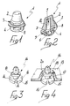
- a replaceable stud for sports shoes is generally indicated by the reference numeral 1 and has a substantially frustum-shaped end portion 2 adapted to interact with the ground, a middle portion 3 shaped so as to constitute a grip element for a tool, and a cylindrical base 4 with a smaller diameter than said middle portion 3.
- Said stud 1 is axially provided with an axial cavity 5 which extends from its base 4 to the inside of the frustum-shaped portion 2.
- said cavity 5 has a base portion 6 with a substantially circular profile from which two opposite circular segments are missing, and a middle portion 7 which constitutes in practice an expansion of the base portion 6, continues in the circular perimetric parts and extends into two transverse slots, respectively 8 and 9, which are open toward the outside of the base 4 and are located at the planar regions of the perimeter of said base portion 6.
- Each slot 8 and 9 is conveniently shaped, on diametrically opposite end positions, so as to define a tooth, respectively indicated by 10 and 11, on the portion 7.
- Said cavity 5 ends with a cylindrical end portion 12.
- the stud 1 can be produced by injection-molding in thermoplastic materials, either monolithically or with a portion 2 constituted by a metallic insert embedded in the rest of the structure.
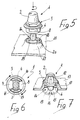
- said pin 14 comprises a disk-like base 15 inserted in a complementarily shaped seat of said sole 13 on the part which is subsequently arranged internally and is closed by the mid-sole; said base is provided with radially arranged notches 16 so that it cannot be extracted or rotated.
- Said substantially cylindrical pin 14 extends axially to said base 15 and is again axially encircled by a raised portion 17 of the sole 13 so as to define a cylindrical annular seat 18 which is equal in height to said base 4 of the stud 1.
- Said pin 14 which is equal in height to the length of said cavity 5, is furthermore provided, in a middle region corresponding to said portion 7 of said cavity, with a flange 19 which is shaped complementarily to the profile of said portion 6 and therefore passes through said portion 6 until it accommodates in said portion 7.
- said cavity portion 7 allows the stud 1 to rotate through approximately one quarter of a turn, as indicated by the arrows of figure 6, so that said flange locks between the slots 8 and 9 and engages the parts.
- said raised portion 17 of the sole 13 is provided, at the top, with a planar portion 20 in which the middle portion 3 of the stud 1 rests upon coupling.
- the stud 1 is mounted as follows: it is initially inserted on the pin 14, ensuring that the base portion 6 of the cavity 5 is arranged so as to be complementary to the flange 19, and a half-rotation of the stud is then performed by means of an appropriate tool, locking said stud.
- Such a technical configuration allows the stud 1 to be more rigidly locked to the sole 13 than currently known types; it has in fact an improved resistance to lateral stresses, since it has both an inner grip on the pin 14 and an outer grip on the raised portion 17.
- Its base furthermore has no sharp reductions in cross section which weaken its structure.
- a replaceable stud for sports shoes is generally indicated by the reference numeral 101 in a second embodiment, and comprises a substantially frustum-shaped end portion 102 adapted to interact with the ground, a middle portion 103 provided with notches adapted to constitute grip elements for a rotation tool and a cylindrical base 104 which is smaller in diameter than said portion 103.
- Said stud 101 is provided with an axial cavity 105 which extends from its base 104 to the inside of the frustum-shaped portion 102.
- said cavity 105 has a base portion 106 which has a substantially circular profile from which two opposite circular segments are missing, and a middle portion 107 which in practice constitutes a widening of said base portion 106, continues in the circular perimetric parts and extends into transverse slots, respectively 108 and 109, which are open toward the outside of the base 104 and are located at the planar regions of the perimeter of said base portion 106.
- each slot 108 and 109 is shaped, at diametrically opposite end positions, so as to define a tooth, respectively indicated by 110 and 111, on the portion 107.
- Said cavity 105 ends with a cylindrical end portion 112.
- a pin 113 rigidly associated with the sole 114 of the shoe is insertable in said cavity 105.
- said pin 113 comprises a disk-shaped base 115 which is inserted in a complementarily shaped seat 117 of the sole 113 on the side which is subsequently closed by the mid-sole.
- Said base 115 has four substantially L-shaped tabs 118 arranged in a cross which insert in complementarily shaped seats of the sole, preventing the rotation of said pin 113.
- An annular raised portion 119 extends orthogonally from said disk-like base 115 and is inserted in a complementarily shaped portion of said seat 117; said raised portion has two opposite radial wings 120 and 121 adapted to engage, upon the partial rotation of the stud 101, appropriate seats 122 and 123 of its base 104, providing a bayonet-like coupling.
- Said substantially cylindrical pin 113 extends axially from said base 115 and is again axially encircled by a raised portion 124 of the sole 114 which continues the wall of said raised portion 119 so as to define an annular seat for said base 104 of said stud 101.
- annular top 125 of said raised portion 124 is conveniently tapered and inserts in a complementarily shaped seat 126 defined in the middle portion 103 of the stud 101 in which an annular seat 127 is also provided for a water-tight sealing ring 128, for example of the O-ring type.
- the pin 113 which is equal in height to the length of said cavity 105, is provided, at the middle region which corresponds to said portion 107 of the cavity, with a flange 129 which is shaped complementarily to the profile of said portion 106 and therefore passes through said portion 106 until it accommodates in said portion 107.
- the configuration of said cavity portion 107 allows the stud 101 a rotation through approximately one quarter of a turn which corresponds to the rotation described above for the bayonet-like coupling, so that said flange locks between the slots 108 and 109 and engages the parts.
- said flange 129 is arranged orthogonally to said wings 120 and 121, and the seats of said flange and of said wings are preset so that the two coupling systems do not interfere.
- the stud 101 is mounted in the same way as the previous one, by inserting it in the pin 113 and rotating it until it locks.
- the materials employed, as well as the dimensions, may be any according to the requirements.
Landscapes
- Footwear And Its Accessory, Manufacturing Method And Apparatuses (AREA)
Applications Claiming Priority (2)
| Application Number | Priority Date | Filing Date | Title |
|---|---|---|---|
| IT3072188U | 1988-09-22 | ||
| IT3072188U IT215698Z2 (it) | 1988-09-22 | 1988-09-22 | Tacchetti sostituibili particolarmente per calzature da caldio e9o sportive. |
Publications (1)
| Publication Number | Publication Date |
|---|---|
| EP0360202A1 true EP0360202A1 (en) | 1990-03-28 |
Family
ID=11231382
Family Applications (1)
| Application Number | Title | Priority Date | Filing Date |
|---|---|---|---|
| EP89117254A Withdrawn EP0360202A1 (en) | 1988-09-22 | 1989-09-17 | Replaceable stud for sports shoes, particularly for soccer shoes |
Country Status (2)
| Country | Link |
|---|---|
| EP (1) | EP0360202A1 (it) |
| IT (1) | IT215698Z2 (it) |
Cited By (17)
| Publication number | Priority date | Publication date | Assignee | Title |
|---|---|---|---|---|
| US5628129A (en) * | 1995-06-06 | 1997-05-13 | Nike, Inc. | Shoe sole having detachable traction members |
| US5655317A (en) * | 1994-01-19 | 1997-08-12 | Grant; David F. | Stud and washer system for golf shoe spikes |
| US5768809A (en) * | 1996-12-23 | 1998-06-23 | Macneill Engineering Company, Inc. | Quick-release spike for footwear |
| US5932336A (en) * | 1995-06-05 | 1999-08-03 | Acushnet Company | Shoe sole |
| US6108944A (en) * | 1996-01-17 | 2000-08-29 | Macneill Engineering Company, Inc. | Quick-release connector |
| US6151805A (en) * | 1996-01-17 | 2000-11-28 | Macneill Engineering Company, Inc. | Quick-release spike for footwear |
| US6301806B1 (en) | 1998-11-02 | 2001-10-16 | Adidas International B.V. | Detachable cleat system |
| EP1240839A1 (en) * | 2001-03-13 | 2002-09-18 | Canon LIAO | Shoe spike assembly having cushioning device |
| US6463681B1 (en) * | 1996-01-17 | 2002-10-15 | Macneil Engineering Company, Inc. | Method of using removable cleat system |
| GB2377616A (en) * | 2001-07-19 | 2003-01-22 | Adam Neil Pressland | Stud for a sports boot |
| DE20211809U1 (de) * | 2002-07-31 | 2003-12-11 | Puma Aktiengesellschaft Rudolf Dassler Sport | Schuh |
| US6957503B2 (en) | 2002-09-05 | 2005-10-25 | Adidas International Marketing, B.V. | Magnetically operable studs for footwear |
| WO2006010101A1 (en) * | 2004-07-08 | 2006-01-26 | Cleats Llc | Anti-twist cleat receptacle |
| EP1728448A1 (en) | 2005-05-31 | 2006-12-06 | Lotto Sport Italia S.p.A. | An interchangeable stud structure for sports shoes |
| US7370444B2 (en) | 2004-07-08 | 2008-05-13 | Cleats Llc | Anti-twist cleat receptacle |
| US8898935B2 (en) | 2011-08-03 | 2014-12-02 | Nike, Inc. | Article of footwear with interlocking cleat member and raised base |
| US9521879B2 (en) | 2011-05-17 | 2016-12-20 | Raptor Sports Pty Ltd | Removable stud or cleat assembly for footwear |
Citations (2)
| Publication number | Priority date | Publication date | Assignee | Title |
|---|---|---|---|---|
| EP0061715A2 (de) * | 1981-03-28 | 1982-10-06 | Werner Frör | Sportschuh mit einer mit Greifelementen versehenen Sohle |
| DE3134817A1 (de) * | 1981-09-03 | 1983-03-10 | Sportartikelfabrik Karl Uhl Gmbh, 7460 Balingen | Laufsohle fuer sportschuhe, insbesondere baseballschuhe |
-
1988
- 1988-09-22 IT IT3072188U patent/IT215698Z2/it active
-
1989
- 1989-09-17 EP EP89117254A patent/EP0360202A1/en not_active Withdrawn
Patent Citations (2)
| Publication number | Priority date | Publication date | Assignee | Title |
|---|---|---|---|---|
| EP0061715A2 (de) * | 1981-03-28 | 1982-10-06 | Werner Frör | Sportschuh mit einer mit Greifelementen versehenen Sohle |
| DE3134817A1 (de) * | 1981-09-03 | 1983-03-10 | Sportartikelfabrik Karl Uhl Gmbh, 7460 Balingen | Laufsohle fuer sportschuhe, insbesondere baseballschuhe |
Non-Patent Citations (1)
| Title |
|---|
| N.T.I.S. TECH NOTES, NASA TECH BRIEF, December 1986, page 1340, Springfield, VA, US; D.M. MOORE: "Quick-connect heavy-duty fastener" * |
Cited By (23)
| Publication number | Priority date | Publication date | Assignee | Title |
|---|---|---|---|---|
| US5655317A (en) * | 1994-01-19 | 1997-08-12 | Grant; David F. | Stud and washer system for golf shoe spikes |
| US5987783A (en) * | 1995-06-05 | 1999-11-23 | Acushnet Company | Golf shoe having spike socket spine system |
| US5932336A (en) * | 1995-06-05 | 1999-08-03 | Acushnet Company | Shoe sole |
| US5628129A (en) * | 1995-06-06 | 1997-05-13 | Nike, Inc. | Shoe sole having detachable traction members |
| US6463681B1 (en) * | 1996-01-17 | 2002-10-15 | Macneil Engineering Company, Inc. | Method of using removable cleat system |
| USRE40460E1 (en) | 1996-01-17 | 2008-08-19 | Cleats Llc | Method of using removable cleat system |
| US6151805A (en) * | 1996-01-17 | 2000-11-28 | Macneill Engineering Company, Inc. | Quick-release spike for footwear |
| US6108944A (en) * | 1996-01-17 | 2000-08-29 | Macneill Engineering Company, Inc. | Quick-release connector |
| US5768809A (en) * | 1996-12-23 | 1998-06-23 | Macneill Engineering Company, Inc. | Quick-release spike for footwear |
| US6301806B1 (en) | 1998-11-02 | 2001-10-16 | Adidas International B.V. | Detachable cleat system |
| US6421937B2 (en) | 1998-11-02 | 2002-07-23 | Adidas International B.V. | Detachable cleat system |
| EP1240839A1 (en) * | 2001-03-13 | 2002-09-18 | Canon LIAO | Shoe spike assembly having cushioning device |
| GB2377616A (en) * | 2001-07-19 | 2003-01-22 | Adam Neil Pressland | Stud for a sports boot |
| DE20211809U1 (de) * | 2002-07-31 | 2003-12-11 | Puma Aktiengesellschaft Rudolf Dassler Sport | Schuh |
| US6957503B2 (en) | 2002-09-05 | 2005-10-25 | Adidas International Marketing, B.V. | Magnetically operable studs for footwear |
| US7481009B2 (en) | 2002-09-05 | 2009-01-27 | Adidas International Marketing B.V. | Magnetically operable studs for footwear |
| WO2006010101A1 (en) * | 2004-07-08 | 2006-01-26 | Cleats Llc | Anti-twist cleat receptacle |
| US7370444B2 (en) | 2004-07-08 | 2008-05-13 | Cleats Llc | Anti-twist cleat receptacle |
| EP1728448A1 (en) | 2005-05-31 | 2006-12-06 | Lotto Sport Italia S.p.A. | An interchangeable stud structure for sports shoes |
| US9521879B2 (en) | 2011-05-17 | 2016-12-20 | Raptor Sports Pty Ltd | Removable stud or cleat assembly for footwear |
| US8898935B2 (en) | 2011-08-03 | 2014-12-02 | Nike, Inc. | Article of footwear with interlocking cleat member and raised base |
| US9044069B2 (en) | 2011-08-03 | 2015-06-02 | Nike, Inc. | Article of footwear with interlocking cleat member and raised base |
| US9259057B2 (en) | 2011-08-03 | 2016-02-16 | Nike, Inc. | Article of footwear with interlocking cleat member and raised base |
Also Published As
| Publication number | Publication date |
|---|---|
| IT215698Z2 (it) | 1990-10-24 |
| IT8830721V0 (it) | 1988-09-22 |
Similar Documents
| Publication | Publication Date | Title |
|---|---|---|
| KR100552635B1 (ko) | 신발용 스터드와 소켓의 조합, 스터드 달린 신발용 스터드와 스터드 달린 신발용 소켓 | |
| AU642251B2 (en) | Studs and sockets for studded footwear | |
| EP0248664B1 (en) | Studs for articles of footwear | |
| US6272774B1 (en) | Shoe cleats | |
| EP1071351A1 (en) | Quick-release connector | |
| US7137213B2 (en) | Studded footwear | |
| JP3824859B2 (ja) | 靴用滑り止め | |
| US20070209239A1 (en) | Studded Footwear | |
| EP1492425B1 (en) | Studded footwear | |
| EP1492426B1 (en) | Studded footwear | |
| US7726043B2 (en) | Studded footwear | |
| EP0163823B1 (en) | Screw-on stud for sports shoes | |
| EP2608690B1 (en) | Cleat attachment system | |
| JPS61135602A (ja) | スポーツシユーズ、特にフツトボールシユーズ用のクリートシステム | |
| WO1992011781A1 (en) | Studs for footwear | |
| GB2433412A (en) | Studded footwear |
Legal Events
| Date | Code | Title | Description |
|---|---|---|---|
| PUAI | Public reference made under article 153(3) epc to a published international application that has entered the european phase |
Free format text: ORIGINAL CODE: 0009012 |
|
| AK | Designated contracting states |
Kind code of ref document: A1 Designated state(s): DE FR GB IT |
|
| 17P | Request for examination filed |
Effective date: 19900611 |
|
| STAA | Information on the status of an ep patent application or granted ep patent |
Free format text: STATUS: THE APPLICATION IS DEEMED TO BE WITHDRAWN |
|
| 18D | Application deemed to be withdrawn |
Effective date: 19920331 |