EP0360320A1 - Dispositif de montage à distance d'une pièce d'assemblage - Google Patents
Dispositif de montage à distance d'une pièce d'assemblage Download PDFInfo
- Publication number
- EP0360320A1 EP0360320A1 EP89202223A EP89202223A EP0360320A1 EP 0360320 A1 EP0360320 A1 EP 0360320A1 EP 89202223 A EP89202223 A EP 89202223A EP 89202223 A EP89202223 A EP 89202223A EP 0360320 A1 EP0360320 A1 EP 0360320A1
- Authority
- EP
- European Patent Office
- Prior art keywords
- built
- housing
- mounting
- guide rails
- flange
- Prior art date
- Legal status (The legal status is an assumption and is not a legal conclusion. Google has not performed a legal analysis and makes no representation as to the accuracy of the status listed.)
- Withdrawn
Links
- 238000009434 installation Methods 0.000 claims description 7
- 210000000078 claw Anatomy 0.000 claims 1
- 238000011161 development Methods 0.000 description 1
- 230000018109 developmental process Effects 0.000 description 1
- 238000012958 reprocessing Methods 0.000 description 1
- 238000003466 welding Methods 0.000 description 1
Images
Classifications
-
- F—MECHANICAL ENGINEERING; LIGHTING; HEATING; WEAPONS; BLASTING
- F16—ENGINEERING ELEMENTS AND UNITS; GENERAL MEASURES FOR PRODUCING AND MAINTAINING EFFECTIVE FUNCTIONING OF MACHINES OR INSTALLATIONS; THERMAL INSULATION IN GENERAL
- F16K—VALVES; TAPS; COCKS; ACTUATING-FLOATS; DEVICES FOR VENTING OR AERATING
- F16K5/00—Plug valves; Taps or cocks comprising only cut-off apparatus having at least one of the sealing faces shaped as a more or less complete surface of a solid of revolution, the opening and closing movement being predominantly rotary
- F16K5/08—Details
- F16K5/14—Special arrangements for separating the sealing faces or for pressing them together
- F16K5/20—Special arrangements for separating the sealing faces or for pressing them together for plugs with spherical surfaces
-
- F—MECHANICAL ENGINEERING; LIGHTING; HEATING; WEAPONS; BLASTING
- F16—ENGINEERING ELEMENTS AND UNITS; GENERAL MEASURES FOR PRODUCING AND MAINTAINING EFFECTIVE FUNCTIONING OF MACHINES OR INSTALLATIONS; THERMAL INSULATION IN GENERAL
- F16L—PIPES; JOINTS OR FITTINGS FOR PIPES; SUPPORTS FOR PIPES, CABLES OR PROTECTIVE TUBING; MEANS FOR THERMAL INSULATION IN GENERAL
- F16L55/00—Devices or appurtenances for use in, or in connection with, pipes or pipe systems
Definitions
- the invention relates to a remotely controllable device for the detachable fastening of an exchangeable installation part in an essentially horizontal, stationary pipeline.
- Devices of this type are required in order to be able to replace wearing parts in hot cells of, for example, nuclear power plants, reprocessing plants or the like, which must not be entered.
- the disconnection and connection takes place by means of remote-controlled manipulators, the movements of which are monitored by the fitter using television cameras.
- remote-controlled manipulators the movements of which are monitored by the fitter using television cameras.
- flexible remote-controlled tools must be provided on the one hand, but for economic reasons, on the other hand, only simple gripping, rotating and transporting movements can be realized. Accordingly, the remotely controllable devices must be made as simple as possible and accessible in a certain way.
- DE-OS 33 40 465 relates to a pipe connection device with a pipe part for connecting two fixed end flanges of two pipes which are arranged at a greater distance from one another. It is envisaged that the parting plane of the two flange connections lie in mutually parallel planes, so that the necessary transport and rotary movements can be carried out with essentially the same orientation of the tools. This requirement can generally be met without particular difficulty.
- the flange connection itself is conventional with several Through bolts with nuts designed for each flange and not usable in this form for the intended application, because it is not possible with reasonable effort to produce such normal bolt connections with the tools available in hot cells.
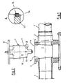
- a rigid pipe housing (2) is shown, which is fixed by welding with a pipe (1) and in a manner not shown to the ground.
- the tubular housing (2) has an assembly opening (3) which is delimited by two opposite planes (4) and (5) which converge in a wedge shape from top to bottom.
- the tubular housing (2) is provided with an essentially horizontal upper fixed flange (6).
- the installation part (7) for example a butterfly valve, has a wedge-shaped housing (8), the Limiting levels (9) and (10) are matched to the mounting opening (3) of the pipe housing (2).
- the built-in part (7) also has a mounting flange (11) with which it can be connected to the flange (6) of the pipe housing (2) in a manner not shown in more detail by means of known, remote-controlled fastening means. From the enlarged illustration A it can be seen that the tube wall (13) of the built-in part (7) has a recess (14) and an annular seal (15) inserted therein.
- the built-in part (7) can be assembled in a very simple manner under the conditions mentioned at the beginning, because it is self-centering due to the inclined boundary surfaces (9) and (10) in the appropriately designed assembly opening (3) and because the contact pressure required for a tight connection can be applied by known remote-controlled fasteners that only require access from above.
- wedge-shaped guide strips can be provided in a similar manner in the tubular housing (2) and on the built-in part (3), but care must be taken to ensure that the mutual distance between the tubular housing (2) and built-in part (7) is in these areas is always slightly larger than between the delimitation levels (4), (5) and (9), (10), so that the contact pressure can be fully transferred to the latter.
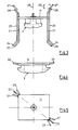
- the device according to the invention can also be equipped with components for precentering, as is shown in FIGS. 3 to 5.
- guide bolts (22) on the fixed flange (6) of the pipe housing (2) and on the mounting flange (11) of the mounting part (7) are essentially parallel to the vertical axis (23) Guide rails (20,21) attached.
- the lower ends (24, 25) of the guide rails (20, 21) are angled outwards and thus form a funnel-shaped inlet area for the guide bolts (22).
- the guide rails (20, 21) are extended upwards and their upper ends (27, 28) are also angled outwards.
- the guide rails are also offset in height by the distance (26) in order to facilitate the pre-adjustment by lowering and turning, the guide bolts (22) serving as a stop.
- the components for pre-adjustment can also be interchanged, i.e. the guide rails are attached to the fixed flange (6) of the pipe housing (2) and the guide bolts are attached to the mounting flange (11) of the mounting part (7).
- the precentering measures prevent the boundary surfaces of the assembly opening (3) or the wedge-shaped housing (8) and in particular the annular seals (15) inserted therein from being damaged in difficult assembly cases.
Landscapes
- Engineering & Computer Science (AREA)
- General Engineering & Computer Science (AREA)
- Mechanical Engineering (AREA)
- Valve Housings (AREA)
Applications Claiming Priority (2)
| Application Number | Priority Date | Filing Date | Title |
|---|---|---|---|
| DE19883830367 DE3830367A1 (de) | 1988-09-07 | 1988-09-07 | Einrichtung zur fernmontage eines einbauteils |
| DE3830367 | 1988-09-07 |
Publications (1)
| Publication Number | Publication Date |
|---|---|
| EP0360320A1 true EP0360320A1 (fr) | 1990-03-28 |
Family
ID=6362438
Family Applications (1)
| Application Number | Title | Priority Date | Filing Date |
|---|---|---|---|
| EP89202223A Withdrawn EP0360320A1 (fr) | 1988-09-07 | 1989-09-04 | Dispositif de montage à distance d'une pièce d'assemblage |
Country Status (2)
| Country | Link |
|---|---|
| EP (1) | EP0360320A1 (fr) |
| DE (1) | DE3830367A1 (fr) |
Cited By (1)
| Publication number | Priority date | Publication date | Assignee | Title |
|---|---|---|---|---|
| DE19515237A1 (de) * | 1995-04-29 | 1996-10-31 | Krohne Messtechnik Kg | Justiervorrichtung |
Families Citing this family (2)
| Publication number | Priority date | Publication date | Assignee | Title |
|---|---|---|---|---|
| DE4314562C2 (de) * | 1993-05-04 | 1997-08-21 | Immanuel Jeschke | Absperrarmatur für eine erdverlegte Versorgungsleitung |
| CN105889627B (zh) * | 2016-05-11 | 2018-12-04 | 四川行之智汇知识产权运营有限公司 | 一种石油管道连接法兰安装的液压对接器 |
Citations (4)
| Publication number | Priority date | Publication date | Assignee | Title |
|---|---|---|---|---|
| US3096999A (en) * | 1958-07-07 | 1963-07-09 | Cameron Iron Works Inc | Pipe joint having remote control coupling means |
| FR1457640A (fr) * | 1965-09-21 | 1966-01-24 | Commissariat Energie Atomique | Dispositif de raccordement à brides |
| EP0133755A2 (fr) * | 1983-07-06 | 1985-03-06 | CROSBY VALVE & GAGE COMPANY | Soupape sphérique facile à entretenir en conditions extrêmes |
| DE3340465A1 (de) * | 1983-11-09 | 1985-05-23 | Deutsche Gesellschaft für Wiederaufarbeitung von Kernbrennstoffen mbH, 3000 Hannover | Rohrleitungsverbindungsvorrichtung zum verbinden von ortsfesten rohrleitungsanschluessen |
Family Cites Families (1)
| Publication number | Priority date | Publication date | Assignee | Title |
|---|---|---|---|---|
| US3799191A (en) * | 1972-01-31 | 1974-03-26 | Exxon Production Research Co | Compartmented underwater equipment |
-
1988
- 1988-09-07 DE DE19883830367 patent/DE3830367A1/de not_active Withdrawn
-
1989
- 1989-09-04 EP EP89202223A patent/EP0360320A1/fr not_active Withdrawn
Patent Citations (4)
| Publication number | Priority date | Publication date | Assignee | Title |
|---|---|---|---|---|
| US3096999A (en) * | 1958-07-07 | 1963-07-09 | Cameron Iron Works Inc | Pipe joint having remote control coupling means |
| FR1457640A (fr) * | 1965-09-21 | 1966-01-24 | Commissariat Energie Atomique | Dispositif de raccordement à brides |
| EP0133755A2 (fr) * | 1983-07-06 | 1985-03-06 | CROSBY VALVE & GAGE COMPANY | Soupape sphérique facile à entretenir en conditions extrêmes |
| DE3340465A1 (de) * | 1983-11-09 | 1985-05-23 | Deutsche Gesellschaft für Wiederaufarbeitung von Kernbrennstoffen mbH, 3000 Hannover | Rohrleitungsverbindungsvorrichtung zum verbinden von ortsfesten rohrleitungsanschluessen |
Cited By (1)
| Publication number | Priority date | Publication date | Assignee | Title |
|---|---|---|---|---|
| DE19515237A1 (de) * | 1995-04-29 | 1996-10-31 | Krohne Messtechnik Kg | Justiervorrichtung |
Also Published As
| Publication number | Publication date |
|---|---|
| DE3830367A1 (de) | 1990-03-15 |
Similar Documents
| Publication | Publication Date | Title |
|---|---|---|
| EP0355270B1 (fr) | Joint pour une traversée de lignes, tels que câbles, tuyaux ou similaires, à travers une ouverture murale | |
| EP0549639B1 (fr) | Element combustible pour reacteur a eau bouillante presentant un support compose d'elements standardises | |
| EP0054827A1 (fr) | Elément combustible pour réacteurs nucléaires à eau bouillante | |
| EP0560764A1 (fr) | Element combustible ou element de commande avec dispositif de verrouillage liberable monte entre le caisson et l'extremite superieure ou inferieure de l'element. | |
| DE3043344A1 (de) | Verbindungsvorrichtung fuer pneumatische geraete | |
| DE1134659B (de) | Kopfstueck an einem Filtergehaeuse | |
| EP0360320A1 (fr) | Dispositif de montage à distance d'une pièce d'assemblage | |
| DE2927844C2 (fr) | ||
| DE3634113C2 (fr) | ||
| DE10163785A1 (de) | Einrichtung zum Zusammenschalten mehrerer hydraulischer oder pneumatischer Komponenten, insbesondere mehrerer Elektromagnetventile | |
| DE3731943C2 (fr) | ||
| EP0175958B1 (fr) | Cabine, notamment cabine en surpression pour la protection par ventilation des installations électriques dans les mines | |
| AT380079B (de) | Kraftwerkebausatz | |
| DE2611936C2 (de) | Gitterförmiger Führungshalter für Rohre für Wärmetauscher | |
| EP0157159B1 (fr) | Armoire de distribution à porte | |
| DE3731936A1 (de) | Fernbedienbare einrichtung zum verbinden von rohrflanschen | |
| DE1450472B2 (de) | Absperrschiebergehaeuse bestehend aus einem gegossenen gehaeusemittelteil und daran befestigten gehaeuseseitenteilen | |
| DE3731941A1 (de) | Fernbedienbare einrichtung zum verbinden von rohrflanschen | |
| DE3638069C1 (de) | Kugelschieber,insbesondere fuer Druckleitungen in Wasserkraftanlagen | |
| DE3731939A1 (de) | Fernbedienbare einrichtung zum verspannen eines absperrorgans zwischen zwei rohrflanschen | |
| DE2546087A1 (de) | Isolierstoffgekapselte schaltanlage fuer schalt-, steuer- und regeleinrichtungen | |
| EP0357931A1 (fr) | Filtre à pression de gaz | |
| EP0641754B1 (fr) | Silo de compostage en plusieurs parties | |
| WO1990006009A1 (fr) | Installation haute tension a cuirasse metallique et a isolation par gaz comprime | |
| DE102020132057A1 (de) | Schutzrohr für eine Hauseinführung, Schutzrohranordnung für Mehrsparten-Hauseinführung sowie eine solche Hauseinführung |
Legal Events
| Date | Code | Title | Description |
|---|---|---|---|
| PUAI | Public reference made under article 153(3) epc to a published international application that has entered the european phase |
Free format text: ORIGINAL CODE: 0009012 |
|
| AK | Designated contracting states |
Kind code of ref document: A1 Designated state(s): DE FR GB |
|
| STAA | Information on the status of an ep patent application or granted ep patent |
Free format text: STATUS: THE APPLICATION HAS BEEN WITHDRAWN |
|
| 18W | Application withdrawn |
Withdrawal date: 19900830 |