EP0360347A2 - Dispositif pour la mesure du spectre de transfert d'impulsions - Google Patents
Dispositif pour la mesure du spectre de transfert d'impulsions Download PDFInfo
- Publication number
- EP0360347A2 EP0360347A2 EP89202353A EP89202353A EP0360347A2 EP 0360347 A2 EP0360347 A2 EP 0360347A2 EP 89202353 A EP89202353 A EP 89202353A EP 89202353 A EP89202353 A EP 89202353A EP 0360347 A2 EP0360347 A2 EP 0360347A2
- Authority
- EP
- European Patent Office
- Prior art keywords
- arrangement
- detector
- examination area
- diaphragm
- symmetry
- Prior art date
- Legal status (The legal status is an assumption and is not a legal conclusion. Google has not performed a legal analysis and makes no representation as to the accuracy of the status listed.)
- Granted
Links
Images

Classifications
-
- A—HUMAN NECESSITIES
- A61—MEDICAL OR VETERINARY SCIENCE; HYGIENE
- A61B—DIAGNOSIS; SURGERY; IDENTIFICATION
- A61B6/00—Apparatus or devices for radiation diagnosis; Apparatus or devices for radiation diagnosis combined with radiation therapy equipment
- A61B6/42—Arrangements for detecting radiation specially adapted for radiation diagnosis
- A61B6/4208—Arrangements for detecting radiation specially adapted for radiation diagnosis characterised by using a particular type of detector
- A61B6/4241—Arrangements for detecting radiation specially adapted for radiation diagnosis characterised by using a particular type of detector using energy resolving detectors, e.g. photon counting
-
- G—PHYSICS
- G01—MEASURING; TESTING
- G01N—INVESTIGATING OR ANALYSING MATERIALS BY DETERMINING THEIR CHEMICAL OR PHYSICAL PROPERTIES
- G01N23/00—Investigating or analysing materials by the use of wave or particle radiation, e.g. X-rays or neutrons, not covered by groups G01N3/00 – G01N17/00, G01N21/00 or G01N22/00
- G01N23/20—Investigating or analysing materials by the use of wave or particle radiation, e.g. X-rays or neutrons, not covered by groups G01N3/00 – G01N17/00, G01N21/00 or G01N22/00 by using diffraction of the radiation by the materials, e.g. for investigating crystal structure; by using scattering of the radiation by the materials, e.g. for investigating non-crystalline materials; by using reflection of the radiation by the materials
- G01N23/20091—Measuring the energy-dispersion spectrum [EDS] of diffracted radiation
Definitions
- the invention relates to an arrangement for measuring the pulse transmission spectrum of X-ray quanta elastically scattered in an examination area, with a polychromatic X-ray emitter arranged on one side of the examination area and a detector arrangement located on the other side of the examination area, measuring the energy of the X-ray quanta, and with two diaphragm arrangements with a common axis of symmetry, which only allow scattered radiation to pass to the detector within a certain scattering angle range, the first of which is arranged between the examination region and the X-ray emitter and the second between the examination region and the detector arrangement.
- Such an arrangement is essentially the subject of German patent application P 37 12 928.
- the momentum transfer of an X-ray quantum is at least approximately proportional to the product of the energy of the X-ray quantum and the scattering angle at which the X-ray quantum was deflected from its previous path during the scattering process.
- the accuracy with which the pulse transmission can be determined therefore depends on how exactly the energy of the X-ray quantum and its scattering angle can be determined.
- the energy of X-ray quanta can be measured very precisely with the aid of a suitable detector, for example made of germanium.
- the accuracy with which the scattering angle can be determined in the above-mentioned arrangement depends on the two diaphragm arrangements.
- the first diaphragm arrangement is designed so that a primary beam with a small cross section (pencil beam) is hidden.
- the second diaphragm arrangement consists of a number of lamellae which are arranged on the lateral surfaces of cones, the tips of which lie on the hidden primary beam in the examination area. If the scattering angle is to be determined as precisely as possible, the lamella dimensions must be as large as possible in comparison to the thickness of the examination area. With thick objects, this leads to very long slats and thus to detectors with a very large diameter. Such detectors are expensive.
- the object of the present invention is to design an arrangement of the type mentioned at the outset such that a relatively precise determination of the pulse transmission is possible even with thick objects with a comparatively small detector arrangement.
- the first diaphragm arrangement is designed in such a way that the X-radiation is transmitted on the lateral surface of a primary beam cone and that the second diaphragm arrangement is shaped such that scattered radiation generated in the examination area strikes the detector arrangement in a rotationally symmetrical manner with respect to the axis of symmetry.
- the invention is not a needle-shaped primary beam that is generated, but a primary beam that lies on the lateral surface of a truncated cone.
- This makes it possible to design the second diaphragm arrangement in such a way that the scattered light beam registered by the detector arrangement converges towards the axis of symmetry or runs parallel to it - and does not diverge, as in the known arrangement - so that even with a large distance between the detector arrangement and the examination area relatively small detectors can be used.
- the second diaphragm arrangement consists of a plurality of cylindrical or conical-shell-shaped collimator bodies (81, 82) which enclose one another and are concentric with the axis of symmetry (3) of the primary beam cone (31).
- the detector arrangement comprises a plurality of concentrically arranged, preferably ring-shaped detectors, each of which detects the scattered radiation passing between two collimator bodies, it is possible to measure the scattered radiation at different depths of the examination area simultaneously and with high efficiency.
- Fig. 1, 1 denotes an X-ray emitter, the anode of which, not shown in detail, preferably consisting of tungsten, has a voltage of 100 kV, for example, in relation to the cathode in the operating state.
- the majority of the X-ray quanta emitted by such an X-ray emitter have an energy between 40 and 80 keV.
- a first diaphragm arrangement which consists of a diaphragm plate 21 with an annular opening for the passage of the x-ray radiation emitted by the x-ray emitter 1.
- the X-rays passing through the opening of the diaphragm plate 21 thus define the lateral surface of a primary beam cone, the tip of which coincides with the focus of the X-ray emitter 1 and the axis of symmetry of which extends through the center of the annular opening.
- the aperture plate 21 points to this Set up a punctiform opening for the passage of a primary beam 3 with a small cross-section. This coincides with the axis of symmetry 3 of the primary beam cone 31.
- the primary beam cone generates, among other things, elastically scattered radiation in the examination area 4. From this scattered radiation 71 that stray radiation disappears by a arranged between the examination region and a detector array 6 second diaphragm arrangement, which is scattered in the primary radiation cone 31 at a defined small angle of, for example, 3.6 o.
- the second diaphragm arrangement 71 comprises two diaphragm plates, each of which is provided with an annular opening which is concentric with the axis of symmetry 3.
- the diameter of this opening in the diaphragm plate adjacent to the examination area is larger than that in the diaphragm plate facing away from it, so that the diaphragm 71 scattered radiation on the lateral surface can let through a secondary beam cone 72 which opens towards the examination area.
- the intersection of the two cones 31 and 81 which have the same axis of symmetry, defines a layer 41 perpendicular to the primary beam 3, from which scattered radiation can strike the detector arrangement 6 through the diaphragm 71.
- the area within the layer in which this scattered radiation is generated has the shape of a ring concentric with the primary beam.
- the diameter of this ring results from the opening angle of the primary beam cone or the secondary beam cone, which can be 1.8 o in each case.
- the dimensions of the detector arrangement 6 are independent of the thickness or the depth of the object 4 which is to be examined with this arrangement.
- Fig. 1 also shows a block diagram of the Auswer te device with which the pulse transmission of the respectively registered X-ray quantum can be determined from the output signal of the energy-resolving detector arrangement, for example a germanium detector.
- the output signal of the detector 6 is fed to a pulse height analyzer 91 via an amplifier 90 with suitable amplification.
- the pulse height analyzer 91 assigns a digital data word to each output pulse generated by the detector 6, which characterizes the amplitude of this pulse and thus the energy of the X-ray quantum. 128 different data words can be provided, for example, to identify the energy range to be registered by the detector 6.
- a unit 92 counts how often the individual data words occur during a predetermined measurement time and stores these numbers.
- the transmitted spectrum can be derived from the output signal of the detector 5 arranged in front of the diaphragm 71 in the primary beam - as indicated by dashed lines.
- the electronics required for this - the units 90..92 - are not shown in FIG. 1 for the sake of clarity.
- the normalization takes place in a circuit 95 in which the intensity measured for this purpose with the detector 6 is divided by the transmitted intensity for each sub-area of the energy or the pulse transmission.
- the energy or pulse transmission spectrum corrected in this way can be displayed on a display unit 96.
- object 4 which may be a piece of luggage, for example, contains a predetermined substance with a known impulse transmission spectrum, for example explosives
- the function of the units 92, 94 and 95 can be realized with the aid of a microprocessor, which can also control the entire course of the measurement.
- FIG. 2 an arrangement is shown which a spatial resolution in the depth of the object, i.e. in the direction of the primary beam, and which therefore only requires a two-dimensional scanning to examine a three-dimensional object.
- This arrangement is therefore particularly suitable for baggage checks or the like.
- an aperture plate 21 with an annular opening for generating a primary beam cone 31 and with an opening concentric with it for generating a primary beam 3 coinciding with the axis of symmetry of the cone 3.
- the annular opening should expediently have a diameter of 14 mm. This results in an opening angle of the beam of 2 o .
- the examination area is delimited by a plate 22 which is transparent to the x-ray radiation and which is at a distance of eg 250 mm from the plate 21. 3, objects up to a thickness of 250 mm can thus be examined.
- a pinhole 72 At a distance from the aperture plate 22, which is significantly larger than its distance from the X-ray emitter 1, for example 850 mm, there is a pinhole 72, through the opening of which the axis of symmetry of the primary beam cone 31 extends. The radiation passing through this opening strikes a detector arrangement 6 which is at a distance of, for example, 800 mm from the pinhole 72.
- this detector arrangement comprises a circular detector crystal 66 which is provided on one side with a correspondingly large circular electrode 67 and on the other side with a plurality of mutually concentric annular electrodes which have a circular one in the middle Enclose the electrode.
- the electrodes are separated from one another by spaces of, for example, 0.5 mm.
- the ring-shaped electrode 65 with the largest diameter carries ground potential, as does the electrode 67. This therefore acts as a guard electrode for the other electrodes.
- the other electrodes together with the detector crystal 66 and the common electrode 67 each form a detector 60..64, the circular detector 60 being enclosed in the center by four ring-shaped detectors 61, 62, 63 and 64 which are concentric thereto.
- the diameter of the circular detector 60 is so small that it can only be hit by the primary beam through the pinhole 72, but not by stray radiation which the primary beam cone 31 generates within the examination area defined by the plates 21, 22.
- the ring 61 surrounding this detector 60 has a diameter such that stray radiation can be struck through the perforated diaphragm 72, which radiation is generated by the primary beam cone 31 in the first quarter of the examination area adjacent to the diaphragm plate 21.
- the second, third and fourth detectors 62, 63 and 64 likewise detect the scattered radiation which the primary beam cone generates in the second, third and fourth quarters of the examination area.
- each of the detectors 61..64 must be followed by the evaluation electronics designated 90..96 in FIG.
- the central detector 60 has the same function as the detector 5 in the arrangements according to FIG. 1.
- the marginal rays of the x-ray beam registered by the detector arrangement 6, which are assigned to the front or rear edge of the examination area, are designated in the drawing with 33 and 34. It can be seen from this that the scattered radiation assigned to the last quarter of the examination area reaches the outer detector at a larger angle than the scattered radiation from the first quarter of the examination area to the innermost detector. However, the differences are much smaller than can be seen from the not to scale representation in FIG. 3; at the indicated dimensions of the scattering angles are 2.4 to 3.1 o, so that with each of the detectors 61..64 called the same area of the momentum transfer can almost be determined.
- This small difference in scattering angle is due to the fact that the distance between the aperture diaphragm 72 and the diaphragm 22 is substantially greater than the distance from the X-ray emitter 1. This relatively large distance also means that each detector ring only receives scattered radiation which is assigned to a very small scattering angle range.
- the outermost Detktorring 64 receives, for example scattered radiation which o o differs only by 0.1 of a mean scattering angle of approximately 2.95. The deviation is even smaller for the inner detectors.
- the intensity of the scattered radiation measured by the detector arrangement 6 is greater, and accordingly the measurement time is shorter, the larger the opening in the pinhole 72.
- the measurement time is shorter, the larger the opening in the pinhole 72.
- the diameter of the opening in the pinhole is therefore a compromise between the measuring time and the accuracy with which the pulse transmission can be determined.
- a value suitable for the aforementioned dimensions is approximately 3 mm.
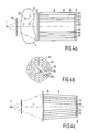
- FIGS. 4a and 4b, or FIG. 5 the compromise between the measuring time and the accuracy with which the pulse transmission can be determined is considerably more favorable than in the arrangement according to FIG. 2.
- Figures 4a and 5 are not to scale; in fact, the dimensions in the horizontal direction are much larger compared to those in the vertical direction.
- the X-ray radiation emanating from the polychromatic X-ray emitter 1 falls on the diaphragm plate 21 with an opening for the primary beam 3 and an annular opening concentric therewith which allows the primary beam cone 31, whose axis of symmetry coincides with the central beam 3.
- the opening angle of the primary beam cone ie the angle between a beam of this cone originating from 1 and the central beam 3 is relatively small, for example 30 .
- the examination area in which the object 4 is located is defined by the aperture plate 21 and a plate 22 parallel to it and transparent to the X-rays.
- the distance between the aperture 21 and the plate 22 can be 400 mm, the distance between the plate 22 and the X-ray source being 600 mm.
- a cylindrical collimator 8 which has a length of 800 mm, for example, and which is arranged concentrically to the axis of symmetry 3.
- This collimator is formed by a number of mutually enclosing cylindrical jacket-shaped collimator bodies 81..85 which have a circular cross section. Only five of them are shown in the drawing, but there may be more of them, for example 8. The achievable depth resolution increases with the number of collimator bodies.
- the inner diameter of the outermost collimator body 81 corresponds to the diameter of the circle which the primary beam cone 31 describes on the plate 22.
- the outer diameter of the innermost collimator body 85 corresponds to the diameter of the annular opening in the aperture 21.
- the collimator bodies for example made of sheet steel, are as thin as possible, but thick enough to absorb the scattered radiation generated in the primary beam cone 31. The same diameter difference results between adjacent collimator bodies.
- the detector arrangement 6 On the opening of the collimator 8 facing away from the plate 22 there is the detector arrangement 6, which consists of a number of ring-shaped detectors 61..64, each of which measures the scattered radiation passing between two adjacent collimator bodies.
- the middle detector 60 measures the intensity of the X-rays in the central beam 3. The signals are processed in an analogous manner as explained in detail in connection with FIG. 1.
- 38 is a scattered beam which originates from a scattering point 32 on the primary beam cone 31 and lies within the examination object 4.
- This Scattering beam runs parallel to the central beam 3 or to the axis of symmetry and therefore corresponds to a scattering angle of 3 o . It passes between the collimator bodies 83 and 84 and strikes the detector ring 62.
- the scattered radiation from points that are closer to the plate 22 passes through collimator bodies located further out, while the scattered radiation from points near the aperture 21 through the collimator body located further inside.
- the thus caused change of the scattering angle is relatively small, if the scattered beam 38 is pivoted about the scattering point 32 in the tangential direction by 0.5 o, this results in a scattering angle change of less than 0.05 o.
- a relatively large arc of one of the ring-shaped detectors 61..64 is assigned to each scattering point, so that the detector - with the same object 4, the same intensity of the X-ray emitter 1 and the same scattering angle inaccuracy - receives significantly more scattered radiation than in the arrangement with a pinhole diaphragm according to . 2.
- slats 80..85 are arranged radially between the diaphragm bodies 81, 85, ie the slats lie in planes that intersect in the axis of symmetry 3.
- the distance between two adjacent slats can be several times as large as the distance between two adjacent collimator bodies.
- the distances between adjacent lamellae, which are each arranged between the same collimator bodies, are largely independent of whether the lamellae are located between the inner or the outer collimator bodies. As a result, more lamellae are provided between the outer collimator bodies than between the inner ones - as the drawing shows.
- the circular or ring-shaped detectors 60..64 which can be semiconductor detectors made of high-purity germanium, must correspond to the dimensions of the primary beam cone in the examination area. Accordingly, the ring-shaped outer detector 64 should have a diameter of around 60 mm. Such semiconductor detectors are expensive.
- the embodiment of the invention shown in Fig. 5 allows the use of detector rings with a reduced diameter. It differs from the embodiment according to FIG. 4a only in that, instead of the cylindrical jacket-shaped collimator body, conical jacket-shaped collimator bodies are used, which taper from the examination area to the detector, the collimator bodies being shaped such that in a longitudinal section containing the central beam 3 the straight lines of intersection Collimator body run parallel to each other.
- the collimator body are located on the lateral surfaces 81..85, for example 1 o, then the diameter of the detector ring may be mm smaller than in the embodiment of Fig. 4a, with otherwise the same dimensions around 28.
- each detector e.g. 62
- the ring-shaped detectors can also be made wider so that they detect the scattered radiation between a collimator body (e.g. 83) and its neighbor after one (85). Although this reduces the resolution at depth, it also improves the signal-to-noise ratio.
Landscapes
- Health & Medical Sciences (AREA)
- Life Sciences & Earth Sciences (AREA)
- Chemical & Material Sciences (AREA)
- Pathology (AREA)
- Engineering & Computer Science (AREA)
- General Health & Medical Sciences (AREA)
- Medical Informatics (AREA)
- Physics & Mathematics (AREA)
- Surgery (AREA)
- Biophysics (AREA)
- Radiology & Medical Imaging (AREA)
- Biomedical Technology (AREA)
- Heart & Thoracic Surgery (AREA)
- Molecular Biology (AREA)
- Nuclear Medicine, Radiotherapy & Molecular Imaging (AREA)
- Animal Behavior & Ethology (AREA)
- High Energy & Nuclear Physics (AREA)
- Public Health (AREA)
- Veterinary Medicine (AREA)
- Optics & Photonics (AREA)
- Dispersion Chemistry (AREA)
- Crystallography & Structural Chemistry (AREA)
- Analytical Chemistry (AREA)
- Biochemistry (AREA)
- General Physics & Mathematics (AREA)
- Immunology (AREA)
- Analysing Materials By The Use Of Radiation (AREA)
- Apparatus For Radiation Diagnosis (AREA)
- Measurement Of Radiation (AREA)
Applications Claiming Priority (4)
| Application Number | Priority Date | Filing Date | Title |
|---|---|---|---|
| DE3832146 | 1988-09-22 | ||
| DE19883832146 DE3832146A1 (de) | 1988-09-22 | 1988-09-22 | Anordnung zur messung des impulsuebertrages |
| DE3909147 | 1989-03-21 | ||
| DE3909147A DE3909147A1 (de) | 1988-09-22 | 1989-03-21 | Anordnung zur messung des impulsuebertrages |
Publications (3)
| Publication Number | Publication Date |
|---|---|
| EP0360347A2 true EP0360347A2 (fr) | 1990-03-28 |
| EP0360347A3 EP0360347A3 (fr) | 1991-07-17 |
| EP0360347B1 EP0360347B1 (fr) | 1995-12-27 |
Family
ID=25872451
Family Applications (1)
| Application Number | Title | Priority Date | Filing Date |
|---|---|---|---|
| EP89202353A Expired - Lifetime EP0360347B1 (fr) | 1988-09-22 | 1989-09-18 | Dispositif pour la mesure du spectre de transfert d'impulsions |
Country Status (4)
| Country | Link |
|---|---|
| US (1) | US5008911A (fr) |
| EP (1) | EP0360347B1 (fr) |
| JP (1) | JPH0628657B2 (fr) |
| DE (2) | DE3909147A1 (fr) |
Cited By (4)
| Publication number | Priority date | Publication date | Assignee | Title |
|---|---|---|---|---|
| EP0462658A3 (en) * | 1990-06-20 | 1992-09-09 | Philips Patentverwaltung Gmbh | Arrangement for the measurement of the pulse transfer spectrum of x-ray quanta |
| EP0556887A1 (fr) * | 1992-02-06 | 1993-08-25 | Philips Patentverwaltung GmbH | Dispositif pour la mesure du spectre de transfert d'impulsions de quantor de rayonnement X |
| US5265144A (en) * | 1991-01-19 | 1993-11-23 | U.S. Philips Corp. | X-ray apparatus |
| WO2006079471A1 (fr) * | 2005-01-26 | 2006-08-03 | Smiths Heimann Gmbh | Collimateur a distance focale reglable |
Families Citing this family (50)
| Publication number | Priority date | Publication date | Assignee | Title |
|---|---|---|---|---|
| GB9311134D0 (en) * | 1993-05-28 | 1993-07-14 | Univ Leicester | Micro-channel plates |
| WO1996003640A1 (fr) * | 1994-07-27 | 1996-02-08 | Muradin Abubekirovich Kumakhov | Procede d'obtention d'une image d'un objet et son dispositif de mise en ×uvre |
| DE4445876B4 (de) * | 1994-12-22 | 2005-08-04 | Philips Intellectual Property & Standards Gmbh | Anordnung zum Messen des Impulsübertragsspektrums von elastisch gestreuten Röntgenquanten |
| DE19504952B4 (de) * | 1995-02-15 | 2005-06-23 | Philips Intellectual Property & Standards Gmbh | Anordnung zum Messen von in einem Untersuchungsbereich elastisch gestreuten Röntgenquanten |
| US6118850A (en) * | 1997-02-28 | 2000-09-12 | Rutgers, The State University | Analysis methods for energy dispersive X-ray diffraction patterns |
| US6054712A (en) * | 1998-01-23 | 2000-04-25 | Quanta Vision, Inc. | Inspection equipment using small-angle topography in determining an object's internal structure and composition |
| US5805663A (en) * | 1997-05-08 | 1998-09-08 | Futec, Inc. | Radiation imaging method and system |
| DE19954663B4 (de) | 1999-11-13 | 2006-06-08 | Smiths Heimann Gmbh | Verfahren und Vorrichtung zur Bestimmung eines Materials eines detektierten Gegenstandes |
| DE19954664B4 (de) * | 1999-11-13 | 2006-06-08 | Smiths Heimann Gmbh | Vorrichtung zur Bestimmung von kristallinen und polykristallinen Materialien eines Gegenstandes |
| DE19954662B4 (de) * | 1999-11-13 | 2004-06-03 | Smiths Heimann Gmbh | Vorrichtung und Verfahren zum Detektieren von unzulässigen Reisegepäckgegenständen |
| US6542578B2 (en) | 1999-11-13 | 2003-04-01 | Heimann Systems Gmbh | Apparatus for determining the crystalline and polycrystalline materials of an item |
| US6504902B2 (en) * | 2000-04-10 | 2003-01-07 | Rigaku Corporation | X-ray optical device and multilayer mirror for small angle scattering system |
| EP1241470B1 (fr) * | 2001-03-14 | 2003-09-24 | YXLON International X-Ray GmbH | Dispositif de mesure du transfert d'impulsion lors de la diffusion élastique de quantas de rayons x dans la région d' un conteneur à inspecter |
| FR2833081B1 (fr) * | 2001-11-30 | 2004-05-07 | Centre Nat Rech Scient | Procede d'analyse volumique aux rayons x de caracteristiques cristallographiques de pieces |
| US20040095626A1 (en) * | 2002-09-30 | 2004-05-20 | Duke University | Reference structures and reference structure enhanced tomography |
| US20050058242A1 (en) | 2003-09-15 | 2005-03-17 | Peschmann Kristian R. | Methods and systems for the rapid detection of concealed objects |
| US7949101B2 (en) | 2005-12-16 | 2011-05-24 | Rapiscan Systems, Inc. | X-ray scanners and X-ray sources therefor |
| US9113839B2 (en) | 2003-04-25 | 2015-08-25 | Rapiscon Systems, Inc. | X-ray inspection system and method |
| GB0525593D0 (en) | 2005-12-16 | 2006-01-25 | Cxr Ltd | X-ray tomography inspection systems |
| US8223919B2 (en) | 2003-04-25 | 2012-07-17 | Rapiscan Systems, Inc. | X-ray tomographic inspection systems for the identification of specific target items |
| US8837669B2 (en) | 2003-04-25 | 2014-09-16 | Rapiscan Systems, Inc. | X-ray scanning system |
| US8451974B2 (en) | 2003-04-25 | 2013-05-28 | Rapiscan Systems, Inc. | X-ray tomographic inspection system for the identification of specific target items |
| US8243876B2 (en) | 2003-04-25 | 2012-08-14 | Rapiscan Systems, Inc. | X-ray scanners |
| JP2007500357A (ja) * | 2003-05-28 | 2007-01-11 | コーニンクレッカ フィリップス エレクトロニクス エヌ ヴィ | ファンビームコヒーレント散乱コンピュータ断層撮影 |
| US7856081B2 (en) | 2003-09-15 | 2010-12-21 | Rapiscan Systems, Inc. | Methods and systems for rapid detection of concealed objects using fluorescence |
| US7366282B2 (en) | 2003-09-15 | 2008-04-29 | Rapiscan Security Products, Inc. | Methods and systems for rapid detection of concealed objects using fluorescence |
| DE102004057743B4 (de) * | 2004-09-08 | 2007-08-09 | Mahlo Gmbh & Co Kg | Verfahren und Vorrichtung zum Bestimmen des Flächengewichtes einer geförderten Materialprobe |
| DE102004060609A1 (de) * | 2004-12-16 | 2006-06-29 | Yxlon International Security Gmbh | Verfahren zum Messen des Impulsübertragungsspektrums von elastisch gestreuten Röntgenquanten |
| DE102005011467B4 (de) * | 2005-03-12 | 2008-02-28 | Smiths Heimann Gmbh | Kollimator mit einstellbarer Brennweite, hierauf gerichtetes Verfahren sowie Röntgenprüfanlage |
| US7738631B2 (en) * | 2005-06-16 | 2010-06-15 | Endicott Interconnect Technologies, Inc. | Energy discriminating scatter imaging system |
| DE102005039642B3 (de) * | 2005-08-22 | 2007-02-22 | Yxlon International Security Gmbh | Kollimatorensystem für eine Röntgendiffraktometrie, Röntgenbeugungsscanner sowie Verfahren zur Durchführung einer Röntgenbeugungsanalyse |
| US7702073B2 (en) * | 2006-09-12 | 2010-04-20 | Morpho Detection, Inc. | Systems and methods for developing a secondary collimator |
| DE102007019334A1 (de) * | 2007-04-24 | 2008-11-06 | Siemens Ag | Blendeneinrichtung für eine zur Abtastung eines Objekts vorgesehene Röntgenvorrichtung, Röntgenvorrichtung zur Abtastung eines Objektes und Verfahren zur Generierung einer Bildinformation eines Objekts mittels einer Röntgenvorrichtung |
| GB0710579D0 (en) * | 2007-06-02 | 2007-07-11 | Univ Cranfield | Detecion of x-ray scattering |
| EP2203736A4 (fr) * | 2007-10-03 | 2016-07-27 | Commw Scient Ind Res Org | Analyseur par diffraction de rayons x à dispersion d'énergie en ligne |
| US9310323B2 (en) | 2009-05-16 | 2016-04-12 | Rapiscan Systems, Inc. | Systems and methods for high-Z threat alarm resolution |
| KR102065318B1 (ko) | 2012-02-03 | 2020-01-10 | 라피스캔 시스템스, 인코포레이티드 | 조합형 산란 및 투과 멀티-뷰 이미징 시스템 |
| WO2014107675A2 (fr) | 2013-01-07 | 2014-07-10 | Rapiscan Systems, Inc. | Dispositif de balayage à rayons x à réseau de détecteurs de discrimination d'énergie partielle |
| KR102167245B1 (ko) | 2013-01-31 | 2020-10-19 | 라피스캔 시스템스, 인코포레이티드 | 이동식 보안검사시스템 |
| US9222900B2 (en) | 2013-03-05 | 2015-12-29 | Danmarks Tekniske Universitet Of Anker Engelundsvej | X-ray diffraction method of mapping grain structures in a crystalline material sample, and an X-ray diffraction apparatus |
| US9222901B2 (en) | 2013-03-05 | 2015-12-29 | Danmarks Tekniske Universitet Anker Engelundsvej | X-ray diffraction method of mapping grain structures in a crystalline material sample, and an X-ray diffraction apparatus |
| US9557427B2 (en) | 2014-01-08 | 2017-01-31 | Rapiscan Systems, Inc. | Thin gap chamber neutron detectors |
| US9498646B2 (en) * | 2014-08-13 | 2016-11-22 | Wisconsin Alumni Research Foundation | Collimator for redirecting compton scattered radiation in stereotactic radiosurgery |
| US10345479B2 (en) | 2015-09-16 | 2019-07-09 | Rapiscan Systems, Inc. | Portable X-ray scanner |
| GB2560164B (en) * | 2017-02-25 | 2022-03-23 | The Nottingham Trent Univ | Sample inspection apparatus employing a diffraction detector |
| WO2018154308A1 (fr) | 2017-02-25 | 2018-08-30 | The Nottingham Trent University | Appareil d'inspection d'échantillon utilisant un détecteur de diffraction |
| GB2560163B (en) * | 2017-02-25 | 2022-07-13 | The Nottingham Trent Univ | Sample inspection apparatus employing a diffraction detector |
| US20190145916A1 (en) * | 2017-11-16 | 2019-05-16 | XRD by Design LLC | Compact, Low Cost Apparatus for Testing of Production and Counterfeit Pharmaceuticals and Other Crystalline Materials |
| US12181422B2 (en) | 2019-09-16 | 2024-12-31 | Rapiscan Holdings, Inc. | Probabilistic image analysis |
| CN118235216A (zh) | 2021-10-01 | 2024-06-21 | 拉皮斯坎控股公司 | 用于并发产生多个基本相似的x射线束的方法和系统 |
Family Cites Families (7)
| Publication number | Priority date | Publication date | Assignee | Title |
|---|---|---|---|---|
| AT285756B (de) * | 1969-02-20 | 1970-11-10 | Otto Dipl Ing Dr Techn Kratky | Blendenanordnung zur Begrenzung eines Röntgenstrahlenbündels |
| DE2312507A1 (de) * | 1973-03-13 | 1974-09-26 | Max Planck Gesellschaft | Geraet fuer roentgenbeugungsmessungen mittels weisser roentgenstrahlen |
| DE3104052A1 (de) * | 1981-02-06 | 1982-08-19 | Philips Patentverwaltung Gmbh, 2000 Hamburg | "roentgenuntersuchungsanordnung mit hoher ortsaufloesung" |
| DE3406905A1 (de) * | 1984-02-25 | 1985-09-05 | Philips Patentverwaltung Gmbh, 2000 Hamburg | Roentgengeraet |
| DE3526015A1 (de) * | 1985-07-20 | 1987-01-22 | Philips Patentverwaltung | Verfahren zum bestimmen der raeumlichen verteilung der streuquerschnitte fuer elastisch gestreute roentgenstrahlung und anordnung zur durchfuehrung des verfahrens |
| DE3712928A1 (de) * | 1987-04-16 | 1988-11-03 | Philips Patentverwaltung | Roentgengeraet zur bestimmung der ortsabhaengigkeit der streueigenschaften in einer schicht eines untersuchungsbereichs |
| US4825454A (en) * | 1987-12-28 | 1989-04-25 | American Science And Engineering, Inc. | Tomographic imaging with concentric conical collimator |
-
1989
- 1989-03-21 DE DE3909147A patent/DE3909147A1/de not_active Ceased
- 1989-09-18 DE DE58909546T patent/DE58909546D1/de not_active Expired - Lifetime
- 1989-09-18 EP EP89202353A patent/EP0360347B1/fr not_active Expired - Lifetime
- 1989-09-19 JP JP1243270A patent/JPH0628657B2/ja not_active Expired - Lifetime
- 1989-09-22 US US07/411,357 patent/US5008911A/en not_active Expired - Lifetime
Cited By (6)
| Publication number | Priority date | Publication date | Assignee | Title |
|---|---|---|---|---|
| EP0462658A3 (en) * | 1990-06-20 | 1992-09-09 | Philips Patentverwaltung Gmbh | Arrangement for the measurement of the pulse transfer spectrum of x-ray quanta |
| US5231652A (en) * | 1990-06-20 | 1993-07-27 | U.S. Philips Corp. | Arrangement for measuring the pulse transmission spectrum of x-ray quanta |
| US5265144A (en) * | 1991-01-19 | 1993-11-23 | U.S. Philips Corp. | X-ray apparatus |
| EP0556887A1 (fr) * | 1992-02-06 | 1993-08-25 | Philips Patentverwaltung GmbH | Dispositif pour la mesure du spectre de transfert d'impulsions de quantor de rayonnement X |
| WO2006079471A1 (fr) * | 2005-01-26 | 2006-08-03 | Smiths Heimann Gmbh | Collimateur a distance focale reglable |
| US8472587B2 (en) | 2005-01-26 | 2013-06-25 | Smiths Heimann Gmbh | Collimator with an adjustable focal length |
Also Published As
| Publication number | Publication date |
|---|---|
| JPH02191436A (ja) | 1990-07-27 |
| DE58909546D1 (de) | 1996-02-08 |
| EP0360347B1 (fr) | 1995-12-27 |
| US5008911A (en) | 1991-04-16 |
| DE3909147A1 (de) | 1990-09-27 |
| JPH0628657B2 (ja) | 1994-04-20 |
| EP0360347A3 (fr) | 1991-07-17 |
Similar Documents
| Publication | Publication Date | Title |
|---|---|---|
| EP0360347B1 (fr) | Dispositif pour la mesure du spectre de transfert d'impulsions | |
| EP0496454B1 (fr) | Appareil de radiographie | |
| EP0209952B1 (fr) | Procédé pour la mesure de la répartition spatiale de rayonnement X diffusé élastiquement ainsi que le dispositif pour la mise en oeuvre du procédé | |
| EP0571017B1 (fr) | Procédé de filtrage pour un système rayons X et agencement pour réaliser ledit procédé de filtrage | |
| DE68920568T2 (de) | Vorrichtung zur Messung von Erdformationen mit hoher räumlicher Auflösung. | |
| DE19954663B4 (de) | Verfahren und Vorrichtung zur Bestimmung eines Materials eines detektierten Gegenstandes | |
| EP0153786B1 (fr) | Appareil à rayons X | |
| EP0556887B1 (fr) | Dispositif pour la mesure du spectre de transfert d'impulsions de quantor de rayonnement X | |
| EP0462658A2 (fr) | Dispositif pour la mesure du spectre de transfert d'impulsions de quanta de rayonnement X | |
| DE102006023309A1 (de) | Verfahren und Vorrichtung zur Erkennung von Material mittels Schnellneutronen und eines kontinuierlichen spektralen Röntgenstrahles | |
| EP0311177A2 (fr) | Système pour examiner un corps avec une source de rayonnement | |
| EP1672359B1 (fr) | Méthode pour mesurer le spectre de transfert d'impulsion de quanta de rayons x diffractés élastiquement | |
| EP0217464B1 (fr) | Procédé pour la détermination de l'atténuation photonique dans un domaine d'un corps et dispositif pour la mise en oeuvre du procédé | |
| DE2105805A1 (de) | Gerat zur Elektronenspektroskopie | |
| DE3638325C2 (fr) | ||
| DE19504952B4 (de) | Anordnung zum Messen von in einem Untersuchungsbereich elastisch gestreuten Röntgenquanten | |
| DE102007045798B4 (de) | Anordnung und Verfahren zur Aufnahme von Röntgenstrahlen-Streuungsbildern | |
| EP2217946B1 (fr) | Dispositif pour la détermination en ligne du contenu d'une substance et procédé utilisant un tel dispositif | |
| DE102004060612B4 (de) | Anordnung zum Messen des Impulsübertragungsspektrums von elastisch gestreuten Röntgenquanten | |
| DE3300566C2 (fr) | ||
| DE19603000A1 (de) | Verfahren zum Kalibrieren einer Anordnung zur Ermittlung des Impulsübertragsspektrums und Kalibriereinheit zur Durchführung des Verfahrens | |
| DE102019215437A1 (de) | Vorrichtung zur Kalibrierung eines PET-Systems | |
| DE3832146A1 (de) | Anordnung zur messung des impulsuebertrages | |
| DE4222227A1 (de) | Anordnung zum Messen des Impulsübertragsspektrums von elastisch gestreuten Röntgenquanten | |
| DE4019613A1 (de) | Anordnung zum messen des impulsuebertragsspektrums von roentgenquanten |
Legal Events
| Date | Code | Title | Description |
|---|---|---|---|
| PUAI | Public reference made under article 153(3) epc to a published international application that has entered the european phase |
Free format text: ORIGINAL CODE: 0009012 |
|
| AK | Designated contracting states |
Kind code of ref document: A2 Designated state(s): DE FR GB IT NL |
|
| PUAL | Search report despatched |
Free format text: ORIGINAL CODE: 0009013 |
|
| AK | Designated contracting states |
Kind code of ref document: A3 Designated state(s): DE FR GB IT NL |
|
| 17P | Request for examination filed |
Effective date: 19920117 |
|
| 17Q | First examination report despatched |
Effective date: 19931102 |
|
| GRAA | (expected) grant |
Free format text: ORIGINAL CODE: 0009210 |
|
| AK | Designated contracting states |
Kind code of ref document: B1 Designated state(s): DE FR GB IT NL |
|
| PG25 | Lapsed in a contracting state [announced via postgrant information from national office to epo] |
Ref country code: IT Free format text: LAPSE BECAUSE OF FAILURE TO SUBMIT A TRANSLATION OF THE DESCRIPTION OR TO PAY THE FEE WITHIN THE PRE;WARNING: LAPSES OF ITALIAN PATENTS WITH EFFECTIVE DATE BEFORE 2007 MAY HAVE OCCURRED AT ANY TIME BEFORE 2007. THE CORRECT EFFECTIVE DATE MAY BE DIFFERENT FROM THE ONE RECORDED.SCRIBED TIME-LIMIT Effective date: 19951227 Ref country code: NL Free format text: LAPSE BECAUSE OF FAILURE TO SUBMIT A TRANSLATION OF THE DESCRIPTION OR TO PAY THE FEE WITHIN THE PRESCRIBED TIME-LIMIT Effective date: 19951227 |
|
| REF | Corresponds to: |
Ref document number: 58909546 Country of ref document: DE Date of ref document: 19960208 |
|
| GBT | Gb: translation of ep patent filed (gb section 77(6)(a)/1977) |
Effective date: 19960313 |
|
| ET | Fr: translation filed | ||
| NLV1 | Nl: lapsed or annulled due to failure to fulfill the requirements of art. 29p and 29m of the patents act | ||
| PLBE | No opposition filed within time limit |
Free format text: ORIGINAL CODE: 0009261 |
|
| STAA | Information on the status of an ep patent application or granted ep patent |
Free format text: STATUS: NO OPPOSITION FILED WITHIN TIME LIMIT |
|
| 26N | No opposition filed | ||
| REG | Reference to a national code |
Ref country code: FR Ref legal event code: CD |
|
| REG | Reference to a national code |
Ref country code: GB Ref legal event code: IF02 |
|
| REG | Reference to a national code |
Ref country code: GB Ref legal event code: 746 Effective date: 20020906 |
|
| REG | Reference to a national code |
Ref country code: FR Ref legal event code: D6 |
|
| PGFP | Annual fee paid to national office [announced via postgrant information from national office to epo] |
Ref country code: DE Payment date: 20081112 Year of fee payment: 20 |
|
| PGFP | Annual fee paid to national office [announced via postgrant information from national office to epo] |
Ref country code: FR Payment date: 20080926 Year of fee payment: 20 |
|
| PGFP | Annual fee paid to national office [announced via postgrant information from national office to epo] |
Ref country code: GB Payment date: 20081031 Year of fee payment: 20 |
|
| REG | Reference to a national code |
Ref country code: GB Ref legal event code: PE20 Expiry date: 20090917 |
|
| PG25 | Lapsed in a contracting state [announced via postgrant information from national office to epo] |
Ref country code: GB Free format text: LAPSE BECAUSE OF EXPIRATION OF PROTECTION Effective date: 20090917 |