EP0360380A2 - Séparation des composants de signaux vidéo numériques composites - Google Patents
Séparation des composants de signaux vidéo numériques composites Download PDFInfo
- Publication number
- EP0360380A2 EP0360380A2 EP89306189A EP89306189A EP0360380A2 EP 0360380 A2 EP0360380 A2 EP 0360380A2 EP 89306189 A EP89306189 A EP 89306189A EP 89306189 A EP89306189 A EP 89306189A EP 0360380 A2 EP0360380 A2 EP 0360380A2
- Authority
- EP
- European Patent Office
- Prior art keywords
- signal
- vertical
- video signal
- line
- composite
- Prior art date
- Legal status (The legal status is an assumption and is not a legal conclusion. Google has not performed a legal analysis and makes no representation as to the accuracy of the status listed.)
- Granted
Links
Images


Classifications
-
- H—ELECTRICITY
- H04—ELECTRIC COMMUNICATION TECHNIQUE
- H04N—PICTORIAL COMMUNICATION, e.g. TELEVISION
- H04N9/00—Details of colour television systems
- H04N9/77—Circuits for processing the brightness signal and the chrominance signal relative to each other, e.g. adjusting the phase of the brightness signal relative to the colour signal, correcting differential gain or differential phase
- H04N9/78—Circuits for processing the brightness signal and the chrominance signal relative to each other, e.g. adjusting the phase of the brightness signal relative to the colour signal, correcting differential gain or differential phase for separating the brightness signal or the chrominance signal from the colour television signal, e.g. using comb filter
Definitions
- This invention relates to methods of and apparatus for component separation of composite digital video signals.
- a composite video (television) signal comprises luminance and chrominance components.
- Two colour difference signals that make up the chrominance signal (U/V signals in the case of PAL and I/Q signals in the case of NTSC) are modulated in quadrature on a colour subcarrier which has a frequency (e.g. 4.43 MHz for PAL and 3.58 MHz for NTSC) towards the upper end of the frequency band or spectrum (e.g. 0 to 5.5 MHz) occupied by the luminance component.
- the modulated sub-carrier is then added to the luminance component to produce the composite signal.
- crosstalk of luminance into chrominance (known as "cross-colour”) and chrominance into luminance (known as "cross-luminance”) can occur when the composite signal is separated into its luminance and chrominance components.
- a composite signal is separated into its luminance and chrominance components by simple filtering techniques.
- a simple notch filter which passes the whole of the spectrum of the composite signal except for a "notch" region centred on the colour subcarrier frequency, because most chrominance energy is concentrated around the colour subcarrier frequency, is used to separate the luminance component.
- the notch filter will pass the sidebands of the chrominance signal and thereby allow some of the chrominance to pass through to appear as crosstalk (cross-luminance) on the luminance, the extent of the crosstalk depending on the colour content of the picture.
- This form of crosstalk arising due to imperfect separation of chrominance from luminance, can manifest itself on a displayed picture in the form of a dot effect at edges of brightly coloured objects, this cross effect being known as "subcarrier crawl".
- a simple bandpass filter which is centred on the colour subcarrier frequency and has a passband of a width similar to that of the band occupied by the chrominance component in the composite signal, is used to separate the chrominance component from the composite signal. Since this filter will pass any luminance energy which is of a high enough frequency to appear within its pass band, it will allow some of the luminance to appear as crosstalk (cross-colour) on the chrominance, the extent of the cross-colour depending upon the luminance content of the picture.
- a striped pattern on, for instance, an article of clothing can, if more than a certain distance from a video camera, have a spatial frequency which will give rise to a high frequency luminance component which appears as cross-colour in the separated chrominance signal and can manifest itself on a displayed picture in the form of a cross effect characterised by a coloured rainbow effect superimposed on the distant striped pattern.
- a better degree of luminance/colour separation than that obtainable by using simple filtering can be achieved by using comb filtering, which takes advantage of the frequency interleaving that takes place between the luminance and chrominance components of the composite signal.
- Such frequency interleaving is possible because the spectral characteristics of both the luminance and chrominance energy are determined by the horizontal and vertical scanning of the video signal.
- the luminance energy within the composite signal is not continuous across the spectrum. Instead, it is concentrated within the spectrum (e.g. 0 to 5.5 MHz) at positions at the line frequency and harmonics thereof, each such concentrated spectral position having sidebands on opposite sides thereof, the spacing between each such pair of sidebands being equal to the field frequency.
- the relationship between the line frequency and the colour subcarrier frequency is, as is well known in the art, chosen so that the chrominance information (which is distributed in a similar manner to the luminance information) is concentrated at positions between the harmonics of the line frequency (where the luminance energy is concentrated) across the region of the spectrum (the upper end) occupied by the chrominance component.
- the chrominance information is frequency interleaved with the luminance information by putting the chrominance information into the gaps or slots between the luminance information towards the upper end of the spectrum of the composite signal.
- a comb filter for separating the chrominance component from the luminance component has plural adjacent passbands, the peaks of which are positioned appropriately (in the frequency domain) within the above-mentioned gaps (and the nulls between the peaks of which are positioned to coincide with the line frequency harmonics at which the luminance energy is concentrated) whereby the filter "combs out” the chrominance energy from the gaps between the luminance energy.
- the nulls are positioned appropriately within the gaps (and the peaks coincide with the line frequency harmonics) whereby the filter "combs out” the luminance energy from between the chrominance energy.
- vertical comb filters In the case of digital composite signals, where digital comb filters are employed, use may be made of vertical (line delay) comb filters, vertical/temporal (field delay) comb filters or temporal (frame delay) filters.
- Vertical comb filters act within a field of the signal between vertically adjacent samples in different lines of the field. They effect a combing action as just described above. They provide a degree of luminance/chrominance separation which, in general, is much better than that provided by simple filtering.
- a vertical/temporal (field delay) filter provides a degree of separation which, in general, is even better than that provided by a vertical filter, in that it acts between samples in different fields and performs a finer combing action between interleaving field sidebands that are disposed around the concentrated regions of luminance and chrominance energy that appear in the spectrum.
- Vertical/temporal filters act between respective consecutive fields, whereby they have a characteristic in the frequency domain which is similar to that of vertical filters except that the peak locations are determined by the field frequency rather than by the line frequency.
- a temporal (frame delay) filter which acts in a purely temporal sense, between samples in different frames, is (in principle) even better.
- Comb filters in general provide a considerably better degree of component separation (and thus a lesser degree of intercomponent crosstalk) than the simple form of filtering described above, which ignores the frequency interleaving of the component separation and treats the spectrum as if it were continuous. Comb filters are thus better suited to obtaining a high quality interface between composite and component video systems. Nonetheless, crosstalk can occur when comb filters are employed.
- the amount of energy in the gaps or slots in the spectrum between the luminance information are picture-dependent. Thus, if there is a lot of luminance energy in the picture, the slots will tend to fill with luminance energy, to a degree dependent on the picture content, whereby luminance energy will crosstalk into the chrominance regions to provide cross-colour.
- the slots will tend to fill with chrominance energy, to a degree dependent on the picture content, whereby chrominance energy will crosstalk into the luminance regions to provide cross-luminance.
- the inventors have ascertained that such crosstalk can arise due to high vertical energy in the picture, for example due to a vertical transition (i.e. a change of luminance and/or (in particular) chrominance in the picture in the vertical direction within a field, which change is not necessarily associated with movement) and/or due to high vertical/temporal energy in the picture (e.g. due to a picture change between fields caused by movement).
- a temporal (frame delay) comb filter acts purely temporally, while it provides good results for a static picture it is highly susceptible to crosstalk in the case of picture movement.
- the inventors have ascertained that, in general, vertical/temporal (field delay) comb filtering provides a better degree of separation than either vertical (line delay) comb filtering or simple filtering, not only in the case of a static picture but also, in general, in the case of a picture having a moderate amount of movement and a moderate amount of vertical energy.
- a vertical (line delay) comb filter can break down in the case of high vertical energy (e.g. due to vertical chrominance transitions), in that high vertical picture energy can cross fairly readily into its passbands.
- it is not in general so susceptible to movement as a vertical/temporal (field delay) comb filter.
- the direction of movement is relevant: it is not susceptible at all to movement along the temporal axis, the degree of susceptibility thus increasing as the direction of movement goes away from that axis.
- a vertical/temporal (field delay) comb filter is not so susceptible as a vertical (line delay) comb filter to high vertical energy (e.g. due to vertical transitions) whereby, for example, in the case of vertical/temporal filtering, failure at vertical chrominance transitions is much less evident than in the case of vertical filtering.
- UK Patent No. GB-B-2 163 023 (Sony Corporation), which is hereby incorporated herein by reference, discloses apparatus for component separation of a composite video signal, the apparatus comprising means for measuring crosstalk between luminance and chrominance components of the video signal, a vertical comb filter for separating the chrominance component from the composite signal, a vertical/temporal comb filter for separating the chrominance component from the composite signal, and means for switching between the vertical filtering and vertical/temporal filtering in response to the crosstalk measured by the cross talk measuring means so as to reduce cross-effects resulting from the crosstalk.
- the switching preferably was smoothed in order that it would occur no more than once every few samples, rather than (as is possible) on a sample by sample basis, with the intention of avoiding unacceptable switching artifacts (i.e. subjectively unacceptable visible phenomena) in the displayed picture.
- unacceptable switching artifacts i.e. subjectively unacceptable visible phenomena
- switching between different modes of filtering was effected frequently with the intention of providing the best possible picture.
- frequent switching in spite of the smoothing, does give rise to unacceptable switching artifacts.
- another difficulty arose. This was that certain spatial frequencies gave rise to an uncertainty in the algorithm controlling the switching (in accordance with measured crosstalk) whereby an ambiguity as to which mode of filtering to adopt arose. This gave rise to repetitive switching (as often as the smoothing action would permit) at certain picture boundaries, producing unacceptable picture artifacts.
- apparatus for component separation of a composite digital video signal comprising: cross talk measuring means for measuring crosstalk between luminance and chrominance components of the composite digital video signal; a vertical comb filter for separating one of said components from the composite digital video signal; a vertical/temporal comb filter for separating said one component from the composite digital video signal; mixing means operative to mix output signals produced by the vertical comb filter and by the vertical/temporal comb filter, respectively, to produce a mixed output signal containing respective proportions of said output signals; and mixing control means responsive to the crosstalk measured by the crosstalk measuring means to control said proportions in a sense to reduce cross effects in said mixed output signal resulting from said crosstalk.
- a method of component separation of a composite digital video signal comprising: measuring crosstalk between luminance and chrominance components of the composite digital video signal; separating one of said components from the composite digital video signal by a vertical comb filtering operation; separating said one component from the composite digital video signal by a vertical/temporal comb filtering operation; mixing output signals produced by the vertical comb filtering operation and by the vertical/temporal comb filtering operation, respectively, to produce a mixed output signal containing respective proportions of said output signals; and controlling said proportions in response to the measured crosstalk in a sense to reduce cross effects in said mixed output signal resulting from said crosstalk.
- the mixing means is operative to mix the composite digital video signal with said output signals produced by the vertical comb filter and the vertical/temporal comb filter whereby said mixed output signal contains respective proportions of the composite digital video signal and said output signals.
- the controlled mixing of the composite digital video signal together with the output signals produced by vertical and vertical/temporal filtering enables a better degree of reduction of cross-effects to be achieved.
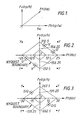
- Figure 1 shows the above-mentioned dimensional frequency spectrum, whose axes are vertical frequency Fv (in units of cycles per picture height (cp/h)), horizontal frequency Fh (in units of cycles per picture width (cp/w)) and temporal frequency Ft (in Hz).
- the derivation of the PAL spectrum shown in Figure 2 is described in more detail in UK Patent No. GB-B-2 163 023 (cited above).
- the NTSC spectrum shown in Figure 3 is derived in an exactly analogous manner, the main difference being that the NTSC colour difference signals I/Q have coincident centres of spectral energy, whereas the PAL colour difference signals U/V have spaced centres of spectral energy.
- the centres of spectral energy for PAL are shown at Y, U and V respectively.
- the centres of spectral energy for NTSC are shown at Y and I/Q respectively.
- the relevant centre Y is that at the origin of the axes Ft and Fv.
- the baseband spectrum is repeated at harmonics of the sampling frequency whereby the rhombic structure is repeated in all directions, positions of Y for four such repeat spectra being shown in each of Figures 2 and 3.
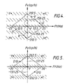
- Figure 4 shows the characteristic of a PAL vertical (line delay) comb filter for chrominance separation superimposed on the spectrum of Figure 2.
- the filter is shown as having stopbands (hatched areas) positioned vertically as shown and passbands (the regions between the shaded areas) positioned vertically to coincide with the chrominance (colour difference) spectral energy centres U and V, in practice it will have a characteristic (as represented schematically by dotted line curves) producing nulls at vertical positions of 0 cp/h, 156.25cp/h and 312.5 cp/h and peaks at the vertical positions of the chrominance spectral energy centres U and V.) It will be thus evident that the characteristic causes the filter to comb out chrominance energy from the luminance energy.
- Figure 5 shows, in similar manner to Figure 4, the characteristic of an NTSC vertical (line delay) comb filter for chrominance separation superimposed on the spectrum of Figure 3.
- the filter is shown as having stopbands (hatched areas) positioned vertically as shown and passbands (the regions between the shaded areas) positioned vertically to coincide with the chrominance spectral energy centres I/Q, in practice it will have a characteristic (as represented schematically by dotted line curves) that nulls at the vertical positions 0 cp/h and 265.5 cp/h and peaks at the vertical positions of the chrominance spectral energy centres I/Q.)
- the characteristic causes the filter to comb out chrominance energy from the luminance energy.
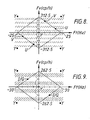
- Figures 6 and 7 show the characteristics of chrominance separation vertical/temporal (field delay) filters for PAL and NTSC, respectively, superimposed on the spectra of Figures 2 and 3, respectively.
- the filters are shown as having stopbands (hatched areas) positioned along vertical/temporal (diagonal) axes passing through the luminance spectral energy centres Y and passbands positioned along the vertical/temporal axes to coincide with the chrominance spectral energy centres U/V or I/Q, whereas in practice the filters will have characteristics (as represented schematically by dotted line curves) that null at the vertical/temporal (diagonal) positions of the luminance energy centre Y and peak at the vertical/temporal (diagonal) positions of the chrominance spectral energy centres U/V or I/Q.)
- the filters will comb out chrominance energy in vertical/temporal space from the luminance energy.
- the luminance and chrominance energy is spread out from the spectral energy centres Y, U, V and I/Q, as represented schematically in Figures 2 and 3 by boundary lines disposed around the respective centres.
- the extent and direction of energy disposed away from the centres Y, U, V and I/Q will depend upon picture content. For example, considering the luminance spectral energy centre Y, in the case of a static picture having a vertical picture content the luminance energy will be distributed along the vertical axis both upwardly and downwardly from the origin.
- the line delay chrominance separation comb filter can in this event fail properly to separate the chrominance from the composite video signal in that it will pass some of this vertical luminance energy, whereby crosstalk of luminance into chrominance (cross-colour) will appear in the output of the line delay comb filter, the extent of the cross-colour depending upon the amount of vertical energy or information in the picture.
- the line delay comb filter can in fact fail dramatically to properly separate the chrominance in the event of a sharp vertical colour transition in the picture, since it relies on the lines between which it filters being correlated. The failure is characterised by a loss of vertical resolution visible to a degree dependent on the impulse response of the filter.
- some of the vertical luminance energy may be passed by the field delay chrominance comb filter, although cross effects arising from high vertical energy (e.g. a vertical colour transition) will be less visible than in the case of a line delay filter because a field delay filter breaks down over only two lines whereby visibility of the failure is restricted to two lines.
- both the field delay and line delay chrominance separation comb filters can pass some of this energy (to an extent dependent on movement) to provide cross-colour in their outputs, though the field delay comb filter is more likely to fail properly to separate the chrominance under conditions of high vertical/temporal energy. That is, while the field delay comb filter provides substantially perfect resolution for static pictures (except in the case of chrominance transitions), maintaining full vertical resolution, it fails to do so in the case of a picture having a substantial amount of movement and having high vertical energy.
- the crosstalk between the luminance and chrominance components is measured by a vertical (line delay) comb filter, which measures vertical crosstalk energy, and a vertical temporal (field delay) comb filter, which measures vertical/temporal crosstalk energy.
- a vertical (line delay) comb filter which measures vertical crosstalk energy
- a vertical temporal (field delay) comb filter which measures vertical/temporal crosstalk energy.
- Figures 8 and 9 show the characteristics of the line crosstalk energy measurement filters for PAL and NTSC, respectively, superimposed on the spectra of Figures 2 and 3, respectively.
- the characteristics are shown in Figures 8 and 9 in a similar way to that in which the characteristics of the chrominance separation vertical (line delay) comb filters are shown in Figures 4 and 5, except that, in Figures 8 and 9, the hatched areas represent passbands rather than stopbands.
- the line crosstalk energy measurement filters pass vertical energy which is located between the vertical positions of the luminance and chrominance spectral energy centres, whereby the outputs of the filters are representative of line (vertical) crosstalk energy.
- Figures 10 and 11 show the characteristics of the field crosstalk energy measurement filters for PAL and NTSC, respectively, superimposed on the spectra of Figures 2 and 3, respectively.
- the characteristics are shown in Figures 10 and 11 in a similar way to that in which the characteristics of the chrominance separation vertical/temporal (field delay) comb filters are shown in Figures 6 and 7, except that, in Figures 10 and 11, the hatched areas represent passbands rather than the stopbands.
- the characteristics have nulls at the diagonal (vertical/temporal) positions of both the luminance spectral energy centres Y and the chrominance spectral energy centres U and V (or I/Q) and have peaks at positions spaced diagonally between the centres.
- the field crosstalk energy measurement filters pass vertical/temporal energy which is located between the diagonal (vertical/temporal) positions of the luminance and chrominance spectral energy centres, whereby the outputs of the filters are representative of field (vertical/temporal) crosstalk energy.
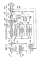
- FIG. 12 is a block schematic circuit diagram of an apparatus embodying the invention for decoding a composite digital video signal.
- a composite analog input video signal (PAL or NTSC) is supplied from an input terminal 10 to a synchronisation signal separator 12.
- a clock signal generator 14 is connected to the synchronisation signal separator 12 and is operative to generate, on a line 16, a 13.5 MHz clock signal which is locked to the line frequency (supplied from the synchronisation signal separator 12) of the input video signal and is supplied to an analog to digital (A/D) converter 18 which samples the analog composite video input signal at the clock frequency of 13.5 MHz to produce a digital composite video signal on a bus 20.
- A/D analog to digital
- a line-locked sampling frequency of 13.5 MHz in accordance with CCIR Recommendation 601 for sampling an analog composite video signal results in an orthogonal sampling structure (for both PAL and NTSC) enabling the use of line and field-based filtering for separation of the luminance and chrominance components of the composite video signal, since all of the samples in all of the lines of each field are disposed orthogonally with respect to one another.
- the digital composite video signal on the bus 20 is applied to: a vertical (line delay) chrominance separation comb filter 22 having a characteristic as shown in Figure 4 (for PAL) or Figure 5 (for NTSC); a vertical/temporal (field delay) chrominance separation comb filter 24 having a characteristic as shown in Figure 6 (for PAL) or Figure 7 (for NTSC); a line crosstalk energy measurement filter 26 having a characteristic as shown in Figure 8 (for PAL) or Figure 9 (for NTSC); and a field crosstalk energy measurement filter 28 having a characteristic as shown in Figure 10 (for PAL) or Figure 11 (for NTSC).
- a vertical (line delay) chrominance separation comb filter 22 having a characteristic as shown in Figure 4 (for PAL) or Figure 5 (for NTSC
- a vertical/temporal (field delay) chrominance separation comb filter 24 having a characteristic as shown in Figure 6 (for PAL) or Figure 7 (for NTSC)
- a line crosstalk energy measurement filter 26
- Combed (comb filtered) output signals from the chrominance separation comb filters 22 and 24 are passed via respective delay circuits 30 and 32 to respective inputs of a mixer 34 described in more detail below with reference to Figure 16.
- the digital composite signal on the bus 20 is also passed directly (i.e. bypassing the chrominance separation comb filters 22 and 24) to a third input of the mixer 34 via a delay circuit 36.
- the respective delays provided by the delay circuits 30, 32 and 36 are selected such that the signals arriving at the respective inputs of the mixer 34 have the same timing.
- the mixer 34 mixes the three signals applied to its respective inputs at a mixing ratio determined by control signals applied thereto on a group of three busses 38, 40 and 42 from a mixer control means 44.
- the mixing ratio is varied in accordance with the control signals such that, at any one time (i.e. for any one sample), the mixed output signal of the mixer 34 comprises a proportion (from zero to 100%) of each of its three input signals, the proportions adding up to unity (100%).
- the mixer control means 44 generates the control signals, as described in more detail below with reference to Figure 16, from a field (vertical/temporal) cross talk energy measurement signal FX obtained from the field crosstalk energy measurement filter 28 and a line (vertical) crosstalk energy measurement signal LX obtained from the line crosstalk energy measurement filter 26.
- the signal FX is representative of vertical/temporal (field) crosstalk energy, which results from picture movement and has a magnitude dependent on the extent of movement as well as the type of picture
- the signal LX is representative of vertical (line) crosstalk energy, which is caused at least predominantly by high vertical picture energy (which is not necessarily associated with picture movement and can therefore arise in the case of both static and moving pictures).
- the resultant mixed output signal from the mixer 34 is passed to a filter 46, which may be a high pass filter (HPF) or a band pass filter (BPF).
- HPF high pass filter
- BPF band pass filter
- the filter 46 is present for the following reason.
- the inputs to the mixer 34 from the comb filters 22 and 24 are combed chrominance
- the bypassed composite signal applied to the third input of the mixer has not been filtered and therefore contains both luminance and chrominance information over the whole composite signal frequency spectrum (e.g. 0 to 5.5 MHz).
- the lower frequency limit of the filter 46 is chosen to be in the region of 3 MHz or so for PAL and 2 MHz or so for NTSC whereby, for both PAL and NTSC, the luminance information below the lower limit of the colour region of the spectrum is cut off.
- the proportion of the bypassed composite video signal supplied to the mixer 34 is effectively subjected to simple filtering (to remove luminance) after it has been mixed with the comb filtered signals in the mixer.
- the filtering effected in the filter 46 also has the effect of cutting off any extraneous information in the spectral region below the lower limit of the colour region that might be passed by the chrominance separation comb filters 22 and 24, in that they operate over the whole spectrum. Should the filter 46 be a band pass filter, its upper cut-off point will be chosen to be at or above the upper end of the composite video signal spectrum so as to cut off any extraneous spectral component above the signal spectrum that may have arrived at the mixer 34 via any of its inputs.
- the output signal of the filter 46 which is, of course, the separated chrominance component of the digital composite video signal, is passed via a bus 48 to one input of a subtracter 50.
- the bypassed composite signal as applied to the third input of the mixer 34 is passed via a delay circuit 52 to another input of the subtracter 50.
- the delay provided by the delay circuit 52 is chosen to equal that between the inputs of the mixer 34 and the output of the filter 46 whereby the signals applied to the respective inputs of the subtracter 50 have the same timing.
- the subtracter 50 subtracts the chrominance component on the bus 48 from the composite signal to provide the luminance component Y, which is supplied to an output 54, whereby both the luminance and chrominance components have been separated.
- the luminance output from the subtracter 50 can, in effect, be considered as if it had been filtered by line and field delay comb filters having characteristics which are the converse of those of the chrominance separation comb filters 22 and 24.
- the separated chrominance component on the bus 48 may then be passed to a chrominance demodulator 56 to separate it into its original colour difference signals (U/V for PAL or I/Q for NTSC) at baseband and apply them to outputs 58, 60, whereby the digital composite video signal has been decoded to provide luminance (Y) and colour difference signals (U/V or 1/Q) at baseband.
- a chrominance demodulator 56 to separate it into its original colour difference signals (U/V for PAL or I/Q for NTSC) at baseband and apply them to outputs 58, 60, whereby the digital composite video signal has been decoded to provide luminance (Y) and colour difference signals (U/V or 1/Q) at baseband.
- the chrominance demodulator 56 may be of the form shown in Figure 13. As shown in Figure 13, the chrominance component on the bus 48 is supplied to respective first inputs of a pair of multipliers 62 and 64. Second inputs of the multipliers 62 and 64 are connected via busses 66 and 68, respectively, to receive relatively phase-displaced colour subcarrier signals (shown in Figure 13 for PAL and NTSC, respectively) which are produced at the appropriate frequency (4.43 MHz for PAL and 3.58 MHz for NTSC) by a colour subcarrier generator 70 from the 13.5 MHz sampling clock signal on the line 16, whereby the chrominance component is demodulated. The colour subcarrier generator 70 is locked to the subcarrier burst in the composite digital video signal in a manner known per se in order to ensure that the modulation is synchronous.
- the outputs of the multipliers 62 and 64 are connected to the outputs 58 and 60 via respective low pass filters (LPFs) 72 and 74.
- LPFs low pass filters
- the filters 72 and 74 which may be finite impulse response (FIR) filters, provide the correct colour bandwidths for the colour difference signals (e.g., in the NTSC system, 1.5 MHz for I and 0.5 MHz for Q). They also should provide good out of band attenuation to ensure the elimination of alias because, at this point, the colour sampling rate is reduced to 6.75 MHz to conform to CCIR Recommendation 601.
- FIR finite impulse response
- the luminance component Y on the output 54 and the colour difference signals U/V or I/Q on the terminals 58 and 60 may then be combined in a manner known per se, to provide, for example, an analog R-G-B output, and/or an analog Y/R-Y/B-Y output and/or a digital R-G-B output.
- Figure 14 shows an example of an FIR filter configuration that can be used for both the line delay and field delay chrominance separation comb-filters 22 and 24, in each case for both PAL and NTSC.
- the filter input is connected to two tandem-connected delays 76, 78.
- the filter has three taps (at the input of the first delay 76, at the junction of the delays 76 and 78 and at the output of the delay 78) which are connected to first inputs of respective multipliers 80, 82 and 84.
- Weighting coefficients of -1/4, +1/2 and -1/4 are applied to second inputs of the multipliers 80, 82 and 84, respectively.
- the coefficients are alternately negative and positive due to the change of phase of chrominance (90 o for PAL and 180 o for NTSC) between lines - either within a field or between fields - in both PAL and NTSC, whereby the filter takes account of chrominance and ignores luminance (which does not change phase between lines).
- the outputs of the multipliers 80, 82 and 84 are summed in an adder 86 to produce the output of the filter.
- the values of the delays 76 and 78 will vary in accordance with whether the filter is a line delay or a field delay filter and in accordance with whether the filter has to act on a PAL or an NTSC signal. In all cases, however, the delay is expressed in units of line delay H, namely the time delay of 64 microseconds between vertically adjacent positions in two successive lines of a field.
- each of the delays 76 and 78 is 2H for PAL and 1H for NTSC, thereby to produce the vertical characteristics shown in Figures 4 and 5, respectively.
- the delay values differ between PAL and NTSC due to the different phase changes between lines (see above) encountered in the cases of PAL and NTSC, respectively.
- the filter of Figure 14 is a vertical/temporal (field delay) chrominance separation comb filter
- the value of each of the delays 76 and 78 is 312H (i.e. one whole field delay of 312.5H, less 1/2H) for PAL and 263H (i.e. one whole field delay of 262.5H, plus 1/2H) for NTSC, thereby to produce the diagonal, vertical/temporal characteristics shown in Figures 6 and 7, respectively.
- Figure 15 shows an example of an FIR filter configuration that can be used for both the line crosstalk and field crosstalk energy measurement filters 26 and 28, in each case for both PAL and NTSC.
- the filter input is connected to a single delay 88 which has taps at its respective ends connected to first inputs of respective multipliers 90 and 92.
- Weighting coefficients of +1/2 and -1/2 are applied to second inputs of the multipliers 90 and 92, respectively.
- the coefficients are alternately negative and positive for the same reason as mentioned above in the description of Figure 14.
- the outputs are summed in an adder 94 to produce the output of the filter.
- the filter of Figure 15 is a line crosstalk energy measurement filter
- the value of the delay 88 is 4H for PAL and 2H for NTSC, thereby to produce the vertical characteristics shown in Figure 8 and 9, respectively.
- the filter of Figure 15 is a field crosstalk energy measurement filter
- the value of the delay 88 is 624H for PAL and 526H for NTSC, thereby to produce the diagonal, vertical/temporal characteristics shown in Figures 10 and 11, respectively.
- the apparatus as so far described could be embodied as a single standard (i.e. PAL or NTSC) decoder, it can in fact also readily be designed, in particular in view of the fact that the same configuration can be used for the filters 22, 24, 26 and 28 whether the standard is PAL or NTSC, as a multistandard (PAL or NTSC) decoder.
- PAL or NTSC multistandard
- the major changes necessary to make the apparatus compatible with both PAL and NTSC are: (i) a facility to switch the delays 76, 78 and 88 in the filters 22, 24, 26 and 28 between the different values mentioned above (a change in the weighting coefficients is not needed); and (ii) a facility to switch the colour subcarrier generator 70 so that it either produces a frequency of 4.43 MHz for PAL (with the phase relationship for PAL noted in Figure 13) or a frequency of 3.58 MHz for NTSC (with the phase relationship for NTSC noted in Figure 13).
- PAL/NTSC multistandard
- a standard selector 96 which is controllable by a select standard signal applied to an input terminal 98 to cause the delays 76, 78 in the filters 22 and 24, and the delays 88 in the filters 26 and 28, to be switched between their different values (as mentioned above) appropriate to PAL and NTSC, to cause the colour subcarrier signal 70 to produce signals (for application to the chrominance demodulator 56) appropriate to PAL or NTSC, and to effect the minor changes mentioned above.
- each of the filters 22, 24, 26 and 28 need not be provided with respective sets of the delays 76, 78 and 80. (This applies whether the decoder is single standard or multistandard).
- the decoder is single standard or multistandard.
- the switches for selecting between the delays appropriate for PAL and NTSC operation can be incorporated in the memory block.
- PAL and NTSC have been used above, at least to some extent, as implying the type of transmission standard used in, for example, the UK and the USA, respectively, in which the number of lines and field frequencies are 625/50 Hz and 525/60 Hz, respectively. It must be remembered, however, that the terms PAL and NTSC strictly apply only to the colour systems used and are in principle independent of the number of lines and field frequency.
- the NTSC standard does not vary substantially over the countries in which it is employed from the FCC standard defined in the USA, i.e. NTSC colour system, 525 lines, 60 Hz field frequency and 3.58 MHz colour subcarrier frequency.
- PAL transmission standards vary between different countries and can in fact be characterised fully only by the definition of a number of parameters including the colour system (i.e. PAL) and various other factors such as number of lines, field frequency and colour subcarrier frequency.
- a multistandard apparatus as described above will in fact work with PAL/I (the standard used in the UK and other countries), PAL/N (which is very similar to PAL/I but has a colour subcarrier frequency of 3.58 MHz) and PAL/M (which uses the PAL colour system but otherwise is similar to NTSC), as well at NTSC.
- PAL/I and NTSC the delays in the filters 22, 24, 26 and 28 and the colour subcarrier generator 70 must be switched as described above.
- the filters 22, 24, 26 and 28 are switched as for PAL and the colour subcarrier generator 70 is switched to provide colour subcarrier signals which have the same phase relationship as for PAL/I, but a similar frequency that used for NTSC. (The frequency is not exactly the same as NTSC, the exact frequencies for NTSC and PAL/N being 3579545 ⁇ 10 Hz and 3582056.25 ⁇ 5 Hz, respectively).
- the filters 22, 24, 26 and 28 are switched as for NTSC and the colour subcarrier generator 70 is switched to provide colour subcarrier signals which have the same phase relationship as PAL/I, but a similar frequency (3575611.49 ⁇ 10 Hz) to that (3579545 ⁇ 10 Hz) used for NTSC.
- Figure 16 shows in more detail the mixer 34 and mixer control means 44 shown only in outline in Figure 12.
- the field crosstalk energy measurement signal FX from the measurement filter 28 and the line crosstalk energy measurement signal LX from the line crosstalk energy measurement filter 26 are supplied to respective high pass or band pass filters 100 and 102 which limit the spectral region of measurement to the modulated colour bandwidth.
- the measurement signals FX and LX are then passed to respective programmable read only memories (PROMs) 104 and 106 which function to discard the signs of their input signals (which may be positive or negative) since only the absolute value of the crosstalk measurements are of significance.
- PROMs programmable read only memories
- the signals are passed via respective FIR low pass filters (LPFs) 108 and 110 which filter out noise (which has a high frequency characteristic) from the signals, to PROMs 112 and 114 which serve only to reduce the number of bits in the signal to reduce hardware requirements.
- LPFs FIR low pass filters
- the modified field and line energy measurement signals emerging from the PROMs 112 and 114 are each passed to respective inputs of each of a bypass coefficient PROM 116, a field coefficient PROM 118 and a line coefficient PROM 120.
- Each of the PROMs 116, 118, 120 is responsive to the values of the signals FX′ and FL′ applied thereto to produce, on a respective one of the busses 38, 40 and 42 (which are connected to outputs of the PROMs 116, 118 and 120, respectively), on a sample by sample basis, a respective coefficient.
- the PROM 116 produces a bypass coefficient CB on the bus 38
- the PROM 118 produces a field coefficient CF on the bus 40
- the PROM 120 produces a line coefficient CL on the bus 42.
- Each of the PROMs 116, 118 and 120 is programmed to respond to the values of the signals FX′ and LX′, in a respective different way.
- the PROMs 116, 118 and 120 are programmed such that, at any time, the values of the coefficients, CB, CF and CL add up to unity. This is because, as will now be described, the values of the coefficients CE, CF and CL are used to control the proportions in which the mixer 34 mixes the bypassed composite video signal, the line delay combed chrominance signal (i.e. the chrominance signal separated by the field delay comb filter 24) and the field delay combed chrominance signal (i.e. the chrominance signal separated by the line delay comb filter 22), respectively, in order to produce the mixed output signal.
- the mixer 34 mixes the bypassed composite video signal
- the line delay combed chrominance signal i.e. the chrominance signal separated by the field delay comb filter 24
- the field delay combed chrominance signal i.e. the chrominance signal separated by the line delay comb filter 22
- the mixer 34 comprises three multipliers 122, 124 and 126 and three adders 128, 130 and 132.
- First inputs of the multipliers 122, 124 and 126 are connected to receive the bypassed composite signal, the field delay combed chrominance signal and the line delay combed chrominance signal, respectively.
- Second inputs of the multipliers 122, 124 and 126 are connected to receive the coefficients CB, CF and CL, respectively.
- the output of the multiplier 122 is connected to one input of the adder 128, which has a second (“carry”) input set to zero.
- the output of the multiplier 124 is connected to one input of the adder 130, which has a second ('carry”) input connected to the output of the adder 128.
- the output of the multiplier 126 is connected to one input of the adder 132, which has a second ("carry") input connected to the output of the adder 130.
- the output of the adder 132 which forms the output of the mixer 34, thus produces a mixed signal in which the proportions of the bypassed composite signal, the field delay combed chrominance signal and the line delay combed chrominance signal (i.e. the mixing ratio therebetween) are governed by the coefficients CB, CF and CL, respectively, produced by the mixer control means 44.
- the first of the above-mentioned exemplary ways of establishing the relationships programmed in the PROMs 116, 118 and 120 adopts the following general guidelines.
- the picture has a high degree of vertical energy but not much vertical/temporal energy, that is when the line crosstalk energy signal LX′ is high with respect to the field crosstalk energy signal FX′, which indicates that the line delay filter 22 is likely to break down to produce crosstalk, and that so also (though to a lesser extent) is the field delay filter 24, the coefficients CB, CF and CL are varied in a sense that the mixing ratio is biassed towards the mixed signal being predominantly bypassed composite, a lesser amount of field delay separated chrominance and a lesser amount still of line delay separated chrominance.
- the coefficients comply with the relationship CB>CF>CL.
- the coefficients CB, CF and CL are varied in a sense to bias the mixing ratio towards being such that the mixed signal is formed predominantly from line delay separated chrominance, to a lesser extent from the field delay separated chrominance, and to a lesser extent still from bypassed composite.
- the coefficients comply with the relationship CL>CF>CE.
- field delay separated chrominance is preferred since, with a picture not having either an excessive amount of movement or an excessive amount of vertical energy, this mode gives the best picture. That is, in this event, the coefficients comply with the relationships CF>CL and CF>CB.
- Figure 17 a plot of the field crosstalk energy measurement signal FX′ against the line crosstalk energy measurement signal LX′ is shown divided into three regions designated B (indicating that bypassed composite is predominant over field delay separated chrominance which is in turn predominant over line delay separated chrominance), F (indicating that field delay separated chrominance is predominant over line delay separated chrominance and over bypassed composite) and L (indicating that line delay separated chrominance is predominant over field delay separated chrominance which is in turn predominant over bypassed composite).
- B indicating that bypassed composite is predominant over field delay separated chrominance which is in turn predominant over line delay separated chrominance
- F indicating that field delay separated chrominance is predominant over line delay separated chrominance and over bypassed composite
- L indicating that line delay separated chrominance is predominant over field delay separated chrominance which is in turn predominant over bypassed composite.
- Figure 18 shows a table of characters F, L and B plotted in a 32 x 32 array of positions (0 to 31) corresponding to a plot of FX′ against LX′.
- the table is set up and edited manually, as a result of extensive study of test pictures, to decide empirically (and subjectively) on what is thought to be the best set of relationships.
- the characters F, L and B represent field delay separation (comb filtering), line delay separation (comb filtering) and bypassed composite, respectively.
- the table is then read by a program which generates the contents of the PROMs 116, 118 and 120.
- the mixer control means 44 includes a vertical transition detector which is operative to detect vertical transitions and to over-ride the programs of the PROMs 116, 118 and 120 in the event of detecting such transitions to bias the mixing ratio to increase (e.g. to 100%) the proportion of bypassed composite in the output of the mixer 34.
- the vertical transition detector comprises a pair of noise reduction infinite impulse response (IIR) low pass filters (LPFs) 134 and 136 having inputs connected to the outputs of the PROMs 104 and 106, respectively, a bypass enhancement PROM 138 having inputs connected to outputs of the IIR LPFs 134 and 136, and an up/down counter 140 having an input connected to an output of the PROM 138 and an output connected to a further input of each of the PROMs 116, 118 and 120.
- the bypass enhancement PROM 138 is programmed to be responsive to its two inputs as follows. If the inputs are equal and each greater than zero the PROM 138 increments the counter 140; if the relationship of the inputs is uncertain the PROM holds the count; and otherwise it causes the counter 140 to count down.
- the bypass enhancement PROM 138 can, for example, be programmed by means of the same program used to program the coefficient PROMs from the table shown in Figure 18.
- the program further weights the number b (the coefficient CB) according to the value of the three most significant bits of the address of the bypass coefficient PROM 116. It does this in such a way that the number b can only be equal to 255 (i.e. the coefficient CB can only be equal to unity) if the output of the counter 140 driven by the bypass enhancement PROM 138 is equal to 1111 or 1110, the least significant bit of the counter 140 (which produces a 5-bit output) being ignored.
- the contents of the bypass enhancement PROM 138 in the case of the table shown in Figure 18 are shown in a table represented in Figure 19.
- the inputs of the PROM 138 are the five least significant bits of the outputs of the IIR LPFs 134 and 136. In the table represented in Figure 19, the value 8 makes the counter 140 count up, the value 4 makes it hold its count and the value 0 makes it count down.
Landscapes
- Engineering & Computer Science (AREA)
- Multimedia (AREA)
- Signal Processing (AREA)
- Processing Of Color Television Signals (AREA)
Applications Claiming Priority (2)
| Application Number | Priority Date | Filing Date | Title |
|---|---|---|---|
| GB8822394A GB2223142B (en) | 1988-09-23 | 1988-09-23 | Separating components of composite digital video signals |
| GB8822394 | 1988-09-23 |
Publications (3)
| Publication Number | Publication Date |
|---|---|
| EP0360380A2 true EP0360380A2 (fr) | 1990-03-28 |
| EP0360380A3 EP0360380A3 (fr) | 1992-03-18 |
| EP0360380B1 EP0360380B1 (fr) | 1996-02-14 |
Family
ID=10644132
Family Applications (1)
| Application Number | Title | Priority Date | Filing Date |
|---|---|---|---|
| EP89306189A Expired - Lifetime EP0360380B1 (fr) | 1988-09-23 | 1989-06-19 | Séparation des composants de signaux vidéo numériques composites |
Country Status (7)
| Country | Link |
|---|---|
| US (1) | US5006927A (fr) |
| EP (1) | EP0360380B1 (fr) |
| JP (1) | JPH02186788A (fr) |
| KR (1) | KR0159924B1 (fr) |
| CA (1) | CA1315395C (fr) |
| DE (1) | DE68925664T2 (fr) |
| GB (1) | GB2223142B (fr) |
Cited By (4)
| Publication number | Priority date | Publication date | Assignee | Title |
|---|---|---|---|---|
| EP0616475A3 (fr) * | 1993-03-17 | 1994-12-21 | Samsung Electronics Co Ltd | Circuit de traitement de signal vidéo adaptif. |
| WO1997039589A1 (fr) * | 1996-04-12 | 1997-10-23 | Snell & Wilcox Limited | Procede et appareil de decodage de signaux video composites |
| EP0840526A1 (fr) * | 1996-10-29 | 1998-05-06 | Daewoo Electronics Co., Ltd | Circuit de préparation de signaux de luminance et de chrominance avec ajustement en fonction du mouvement |
| WO2004064412A1 (fr) * | 2003-01-14 | 2004-07-29 | Koninklijke Philips Electronics N.V. | Procede et dispositif de separation d'un signal de chrominance d'un signal de bande de base video composite |
Families Citing this family (12)
| Publication number | Priority date | Publication date | Assignee | Title |
|---|---|---|---|---|
| KR960016852B1 (ko) * | 1990-05-23 | 1996-12-21 | 삼성전자 주식회사 | 동작 적응형 색신호 합성회로 |
| DE19524794A1 (de) * | 1995-07-07 | 1997-01-09 | Philips Patentverwaltung | Schaltungsanordnung zur Farbsignal-Verarbeitung |
| US5831687A (en) * | 1995-09-05 | 1998-11-03 | Ricoh Company, Ltd. | Color video signal processing method and apparatus for converting digital color difference component signals into digital RGB component signals by a digital conversion |
| DE19609193A1 (de) * | 1996-03-09 | 1997-09-11 | Thomson Brandt Gmbh | Verfahren und Schaltungsanordnung zum Trennen von Luminanz- und Chrominanzsignalen eines FBAS-Signals |
| US5923374A (en) * | 1996-08-08 | 1999-07-13 | Lucent Technologies Inc. | Method and apparatus for reduced-bandwidth transmission of television signals |
| WO2004001496A1 (fr) * | 2002-06-24 | 2003-12-31 | Koninklijke Philips Electronics N.V. | Panneau d'affichage electrochromique dote d'electrodes de correction de diaphonie |
| JP2004159067A (ja) * | 2002-11-06 | 2004-06-03 | Sanyo Electric Co Ltd | 垂直シャープネス装置及びそれを備えたtv受像機 |
| US8553155B2 (en) * | 2003-03-05 | 2013-10-08 | Broadcom Corporation | System and method for three dimensional comb filtering |
| US7339629B2 (en) * | 2004-01-30 | 2008-03-04 | Broadcom Corporation | Method and system for time constant for a 3D comb filter |
| US7492415B2 (en) * | 2004-02-05 | 2009-02-17 | Broadcom Corporation | Method and system for data compression for storage of 3D comb filter data |
| TWI376962B (en) * | 2007-11-09 | 2012-11-11 | Realtek Semiconductor Corp | Method and apparatus for adaptive selection of y/c separation |
| US11677938B2 (en) * | 2008-04-30 | 2023-06-13 | Arris Enterprises Llc | Method to reduce contour artifacts on recursive temporal filters |
Family Cites Families (10)
| Publication number | Priority date | Publication date | Assignee | Title |
|---|---|---|---|---|
| JPS53117329A (en) * | 1977-03-24 | 1978-10-13 | Hitachi Ltd | Processing circuit for color signal |
| GB2078054B (en) * | 1980-06-02 | 1985-03-06 | British Broadcasting Corp | Pal decoding |
| US4636840A (en) * | 1984-08-09 | 1987-01-13 | Rca Corporation | Adaptive luminance-chrominance separation apparatus |
| GB2163023B (en) * | 1984-08-10 | 1987-12-23 | Sony Corp | Decoding digital pal video signals |
| US4703342A (en) * | 1985-01-14 | 1987-10-27 | Nec Corporation | Luminance/chrominance separating apparatus |
| JPS61281696A (ja) * | 1985-06-06 | 1986-12-12 | Sony Corp | 高品位テレビジヨン信号の伝送方式及び磁気記録装置 |
| US4754322A (en) * | 1985-09-30 | 1988-06-28 | Hitachi, Ltd. | YC-signal separation circuit responsive to magnitude of vertical correlation |
| JPH07123307B2 (ja) * | 1986-05-20 | 1995-12-25 | ソニー株式会社 | Y/c分離回路 |
| US4716462A (en) * | 1986-11-25 | 1987-12-29 | Rca Corporation | Motion adaptive television signal processing system |
| JPS63242091A (ja) * | 1987-03-30 | 1988-10-07 | Toshiba Corp | 信号分離回路 |
-
1988
- 1988-09-23 GB GB8822394A patent/GB2223142B/en not_active Expired - Fee Related
-
1989
- 1989-04-07 US US07/334,560 patent/US5006927A/en not_active Expired - Lifetime
- 1989-06-19 DE DE68925664T patent/DE68925664T2/de not_active Expired - Fee Related
- 1989-06-19 EP EP89306189A patent/EP0360380B1/fr not_active Expired - Lifetime
- 1989-06-27 CA CA000604094A patent/CA1315395C/fr not_active Expired - Fee Related
- 1989-09-21 KR KR1019890013564A patent/KR0159924B1/ko not_active Expired - Fee Related
- 1989-09-22 JP JP1247834A patent/JPH02186788A/ja active Pending
Cited By (7)
| Publication number | Priority date | Publication date | Assignee | Title |
|---|---|---|---|---|
| EP0616475A3 (fr) * | 1993-03-17 | 1994-12-21 | Samsung Electronics Co Ltd | Circuit de traitement de signal vidéo adaptif. |
| CN1054018C (zh) * | 1993-03-17 | 2000-06-28 | 三星电子株式会社 | 采用平滑转换器的自适应视频峰化电路 |
| WO1997039589A1 (fr) * | 1996-04-12 | 1997-10-23 | Snell & Wilcox Limited | Procede et appareil de decodage de signaux video composites |
| EP1263241A1 (fr) * | 1996-04-12 | 2002-12-04 | SNELL & WILCOX LIMITED | Procédé et appareil de décodage de signaux vidéo composites |
| EP0840526A1 (fr) * | 1996-10-29 | 1998-05-06 | Daewoo Electronics Co., Ltd | Circuit de préparation de signaux de luminance et de chrominance avec ajustement en fonction du mouvement |
| US5929938A (en) * | 1996-10-29 | 1999-07-27 | Daewoo Electronics Co., Ltd. | Motion adaptive luminance and chrominance signal separating circuit |
| WO2004064412A1 (fr) * | 2003-01-14 | 2004-07-29 | Koninklijke Philips Electronics N.V. | Procede et dispositif de separation d'un signal de chrominance d'un signal de bande de base video composite |
Also Published As
| Publication number | Publication date |
|---|---|
| KR0159924B1 (ko) | 1999-01-15 |
| GB8822394D0 (en) | 1988-10-26 |
| EP0360380B1 (fr) | 1996-02-14 |
| KR900005814A (ko) | 1990-04-14 |
| GB2223142B (en) | 1993-01-06 |
| CA1315395C (fr) | 1993-03-30 |
| EP0360380A3 (fr) | 1992-03-18 |
| GB2223142A (en) | 1990-03-28 |
| US5006927A (en) | 1991-04-09 |
| DE68925664D1 (de) | 1996-03-28 |
| JPH02186788A (ja) | 1990-07-23 |
| DE68925664T2 (de) | 1996-07-18 |
Similar Documents
| Publication | Publication Date | Title |
|---|---|---|
| EP0360380B1 (fr) | Séparation des composants de signaux vidéo numériques composites | |
| CA2027520C (fr) | Filtre a adaptation aux mouvements pour separer les signaux de luminance et de chrominance | |
| KR100388579B1 (ko) | 공통지연소자를갖는휘도/색차를분리시키기위한방법및장치 | |
| US4786963A (en) | Adaptive Y/C separation apparatus for TV signals | |
| US5500686A (en) | Motion adaptive luminance signal/chrominance signal separation filter | |
| GB2198010A (en) | Tv apparatus capable of freeze field display | |
| US6052157A (en) | System and method for separating chrominance and luminance components of a color television system | |
| US4775888A (en) | Motion detector for chrominance signal in TV receiver | |
| CA1296097C (fr) | Detecteur de mouvements pour le signal de chrominance dans un recepteur de television | |
| KR0126472B1 (ko) | 색도 및 휘도 비디오 신호 분리용 적응성 콤필터 및 신호 분리 방법 | |
| JPH071938B2 (ja) | 複合デジタルpal映像信号のデコーディング装置 | |
| US5373329A (en) | Method of picture movement signal detection and associated circuit | |
| KR0158665B1 (ko) | 확장된 복합 텔레비젼 시스템 | |
| JP2794156B2 (ja) | くし形フィルタ | |
| CA2039536C (fr) | Filtre de separation des signaux de luminance et de chrominance s'adaptant au mouvement | |
| JP2786304B2 (ja) | 動き適応型輝度信号色信号分離フィルタ | |
| KR930005614B1 (ko) | 휘도/색도신호 분리회로 | |
| KR920004124B1 (ko) | 복합영상신호의 인터리이브 관계 검출회로 | |
| JP2757495B2 (ja) | 動き適応型輝度信号色信号分離フィルタ | |
| JP2685542B2 (ja) | クロマ信号処理回路 | |
| JPH03274888A (ja) | 動き適応型輝度信号色信号分離フィルタ | |
| JPH03274886A (ja) | 動き適応型輝度信号色信号分離フィルタ | |
| JPH04211595A (ja) | 動き適応型輝度信号/色信号分離フィルタ | |
| JPH03283795A (ja) | 動き適応型輝度信号色信号分離フィルタ | |
| JPH0421295A (ja) | 動き適応型輝度信号色信号分離フィルタ |
Legal Events
| Date | Code | Title | Description |
|---|---|---|---|
| PUAI | Public reference made under article 153(3) epc to a published international application that has entered the european phase |
Free format text: ORIGINAL CODE: 0009012 |
|
| AK | Designated contracting states |
Kind code of ref document: A2 Designated state(s): DE FR GB |
|
| PUAL | Search report despatched |
Free format text: ORIGINAL CODE: 0009013 |
|
| AK | Designated contracting states |
Kind code of ref document: A3 Designated state(s): DE FR GB |
|
| 17P | Request for examination filed |
Effective date: 19920818 |
|
| 17Q | First examination report despatched |
Effective date: 19940518 |
|
| GRAA | (expected) grant |
Free format text: ORIGINAL CODE: 0009210 |
|
| AK | Designated contracting states |
Kind code of ref document: B1 Designated state(s): DE FR GB |
|
| REF | Corresponds to: |
Ref document number: 68925664 Country of ref document: DE Date of ref document: 19960328 |
|
| ET | Fr: translation filed | ||
| PLBE | No opposition filed within time limit |
Free format text: ORIGINAL CODE: 0009261 |
|
| STAA | Information on the status of an ep patent application or granted ep patent |
Free format text: STATUS: NO OPPOSITION FILED WITHIN TIME LIMIT |
|
| 26N | No opposition filed | ||
| REG | Reference to a national code |
Ref country code: GB Ref legal event code: IF02 |
|
| PGFP | Annual fee paid to national office [announced via postgrant information from national office to epo] |
Ref country code: FR Payment date: 20050608 Year of fee payment: 17 |
|
| PGFP | Annual fee paid to national office [announced via postgrant information from national office to epo] |
Ref country code: GB Payment date: 20050615 Year of fee payment: 17 |
|
| PGFP | Annual fee paid to national office [announced via postgrant information from national office to epo] |
Ref country code: DE Payment date: 20050616 Year of fee payment: 17 |
|
| PG25 | Lapsed in a contracting state [announced via postgrant information from national office to epo] |
Ref country code: GB Free format text: LAPSE BECAUSE OF NON-PAYMENT OF DUE FEES Effective date: 20060619 |
|
| PG25 | Lapsed in a contracting state [announced via postgrant information from national office to epo] |
Ref country code: DE Free format text: LAPSE BECAUSE OF NON-PAYMENT OF DUE FEES Effective date: 20070103 |
|
| GBPC | Gb: european patent ceased through non-payment of renewal fee |
Effective date: 20060619 |
|
| REG | Reference to a national code |
Ref country code: FR Ref legal event code: ST Effective date: 20070228 |
|
| PG25 | Lapsed in a contracting state [announced via postgrant information from national office to epo] |
Ref country code: FR Free format text: LAPSE BECAUSE OF NON-PAYMENT OF DUE FEES Effective date: 20060630 |