EP0360405A2 - Capteur du niveau du réfrigérant à deux fils - Google Patents
Capteur du niveau du réfrigérant à deux fils Download PDFInfo
- Publication number
- EP0360405A2 EP0360405A2 EP89308182A EP89308182A EP0360405A2 EP 0360405 A2 EP0360405 A2 EP 0360405A2 EP 89308182 A EP89308182 A EP 89308182A EP 89308182 A EP89308182 A EP 89308182A EP 0360405 A2 EP0360405 A2 EP 0360405A2
- Authority
- EP
- European Patent Office
- Prior art keywords
- circuit
- indicator
- output
- source
- lamp
- Prior art date
- Legal status (The legal status is an assumption and is not a legal conclusion. Google has not performed a legal analysis and makes no representation as to the accuracy of the status listed.)
- Withdrawn
Links
Images


Classifications
-
- G—PHYSICS
- G01—MEASURING; TESTING
- G01F—MEASURING VOLUME, VOLUME FLOW, MASS FLOW OR LIQUID LEVEL; METERING BY VOLUME
- G01F23/00—Indicating or measuring liquid level or level of fluent solid material, e.g. indicating in terms of volume or indicating by means of an alarm
- G01F23/22—Indicating or measuring liquid level or level of fluent solid material, e.g. indicating in terms of volume or indicating by means of an alarm by measuring physical variables, other than linear dimensions, pressure or weight, dependent on the level to be measured, e.g. by difference of heat transfer of steam or water
- G01F23/24—Indicating or measuring liquid level or level of fluent solid material, e.g. indicating in terms of volume or indicating by means of an alarm by measuring physical variables, other than linear dimensions, pressure or weight, dependent on the level to be measured, e.g. by difference of heat transfer of steam or water by measuring variations of resistance of resistors due to contact with conductor fluid
- G01F23/241—Indicating or measuring liquid level or level of fluent solid material, e.g. indicating in terms of volume or indicating by means of an alarm by measuring physical variables, other than linear dimensions, pressure or weight, dependent on the level to be measured, e.g. by difference of heat transfer of steam or water by measuring variations of resistance of resistors due to contact with conductor fluid for discrete levels
- G01F23/243—Schematic arrangements of probes combined with measuring circuits
- G01F23/244—Schematic arrangements of probes combined with measuring circuits comprising oscillating circuits
Definitions
- This invention relates to a liquid level sensor and, more specifically, to a liquid level sensor for use primarily in an automotive environment which is capable of operation using only two wires.
- Liquid level sensors or detectors for determining the level of electrically conductive liquid in a tank or for determining when the level of the electrically conductive liquid in a tank has dropped below a predetermined level are well known and many devices for measuring and/or detecting such levels have been known going into the distant past.
- Such liquid level detectors are often called upon to determine when the liquid level in a tank of electrically conductive liquid has fallen below some predetermined level and to provide an indication or alarm in response thereto.
- One such environment wherein this problem exists which is provided herein only by way of example and not by way of limitation, is in the radiator of an automobile wherein it is necessary that the liquid level be above some predetermined minimum.
- Liquid level sensing and alarm systems for this problem have been designed in the past, such systems generally requiring three wires, one for power, one for output and one for a ground connection. It is highly advantageous, especially with the continually greater number of wires present in automobiles, to minimize the number of wires required therein to perform a selected number of functions. This can be accomplished by providing a circuit which is capable of operating with a diminished number of wires therefrom.
- a plurality of circuits for measuring the level of an electrically conductive liquid specifically, by way of example and not by way of limitation, the level of electrically conductive liquid coolant in an automobile radiator, using a two wire system as opposed to the prior art three wire system.
- the above is accomplished by utilizing an incandescent lamp to provide the alarm signal with the power required to energize the circuit being derived via the lamp whereby the lamp and the circuit are serially connected between the battery terminals (i.e., positive and negative battery terminal or ground).
- the alarm circuits are provided with an oscillator circuit wherein the oscillator performs the dual functions of providing the signal for detection through the probe and providing the drive signal for the output transistor which controls the lamp.
- an oscillator provides pulses having a duty cycle from about 1 to about 50% and a frequency of from about 60 to about 10,000 hertz which are the control signals to control the output circuit for a lamp as well as the signal pulses sent to the probe to determine the status thereof.
- Schmitt triggers determine the status at the probe and, in response thereto, either permit the pulses from the oscillator to turn on the output to turn on the light or to shunt the pulses away from the output to turn off the output.
- the power for the circuit always passes through the lamp, whether or not it is illuminated.
- the output circuit is an SCR which stays on once latched until power thereacross is removed.
- An operational amplifier is used to compare a reference impedance with the impedance present at the probe.
- positive and negative feedback are provided from the output to the input of the operational amplifier, the positive feedback path being shunted to reference potential (ground) when the probe resistance is low to provide no output from the op amp and therefore maintain the SCR off.
- the positive feedback becomes dominant and causes as output to appear from the op amp which turns on the SCR and therefore the lamp also turns on.
- FIGURE 1 there is provided a system schematic diagram which shows an integrated circuit (IC) 1 which contains most of the circuitry in accordance with the first embodiment of the invention.
- the IC has eight terminals, the top terminal being connected to reference voltage via a capacitor C1 as well as to the positive or negative battery terminal, (the particular battery terminal chosen being dependent upon the arrangement of the semiconductors in the IC) via lamp 3.
- the input to the IC is taken from a load 5, represented as a resistor, which is actually a probe in the liquid-containing tank which provides low resistance when disposed in the liquid being monitored and high resistance when out of the liquid.
- the output is connected to a reference resistor 7 which is utilized for comparison as will be discussed hereinbelow.
- a ground connection which, in the case of an automobile environment, can be the chassis.
- the other one of the terminals of the battery will also be connected to the chassis.
- An oscillator terminal is coupled to reference voltage via a capacitor C3 which provides the capacitance required to set the oscillator frequency.
- a P/S terminal, a noise terminal and a delay terminal are each coupled to the reference voltage source via separate capacitors C2, C5 and C6 respectively. Since capacitors are not normally internal to an IC, they are shown connected to the terminals thereof and will be discussed hereinbelow in connection with the circuit of which they are a part.
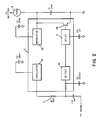
- the IC includes an oscillator 11, a regulator 13, a detector 15 and a delay circuit 17.
- the delay circuit controls the output driver in the form of a bipolar or field effect transistor 19 which is coupled between the regulator 13 and reference voltage (e.g., ground).
- FIGURE 3 there is shown a circuit diagram of the circuit contained in IC 1 of the preferred embodiment in accordance with the present invention.
- This circuit is a voltage divider circuit wherein the lamp 3 will turn off after being energized if the liquid level is restored to its normal level.
- the circuit of FIGURE 3 generates an oscillator signal using a Schmitt trigger inverter 71 with a feedback network comprised of a diode 73 and resistor 75 in parallel with a resistor 77, and an integrating capacitor 79.
- the output of the oscillator is passed through a reference resistor 81 and then to the probe located in the coolant (not shown) via a capacitor 83.
- This forms a voltage divider between the resistor 81 and the impedance of the coolant.
- the capacitor 83 is a DC blocking capacitor since DC current will cause undesirable corrosion of other metals in the coolant.
- the resistor 85 and capacitor 87 filter out electromagnetic radiations in the surrounding environment.
- a Schmitt trigger detector 89 determines when the resistance of the probe is higher than the resistance of the reference 81.
- the single oscillator provides two functions, these being the signal for detection through the probe and the second being to provide the drive signal for the output transistor 109.
- a high duty cycle pulse train e.g., 80% duty cycle square wave
- the voltage across the transistor 109 is approximately the battery voltage, this allowing the storage capacitor 103 to be charged through the diode 117 and resistor 115 with the zener diode 111 providing a reference voltage across the capacitor 113.
- the diode 117 prevents discharge of capacitor 113 when the transistor 109 is on.
- a regulator may be used in place of the zener diode 111.
- the resistor 95 and capacitor 93 provide for the lamp 3 to flash on for a predetermined time (e.g., 1 second) whenever the circuit is powered on.
- FIGURE 4 there is shown a circuit diagram of a second embodiment in accordance with the present invention.
- This circuit is similar to the circuit of FIGURE 3 except that a metastable oscillator is utilized.
- the op amp circuit 125 of the oscillator has both positive feedback via resistor 127 and negative feedback via resistor 129.
- the positive input to the op-amp 125 is taken from a voltage divider composed of resistors 131 and 133 as well as from the positive feedback path which is also coupled to the probe via a DC blocking capacitor 135 and an EMC filter composed of resistor 137 and capacitor 139.
- the negative input to the comparator is taken from the negative feedback path via resistor 129 as well as the reference resistor 141 which is coupled to reference potential via capacitor 143.
- the positive feedback path is shorted (placed in a low resistance path to ground) to ground through the low impedance path of the coolant when the coolant is at or above the predetermined level. Therefore the negative feedback path takes precedence and there is no AC output at the output terminal of the op amp 125.
- the positive feedback path becomes dominant over the negative feedback path and the device provides an output in the form of pulses or oscillations.
- the output of the oscillator is fed through capacitor 145, rectified by diodes 147 and 149 and turns on the SCR 121, the gate thereof being normally held low by resistor 151.
- the lamp 3 When the SCR is turned on, the lamp 3 turns on and the remainder of the circuit becomes disabled because all of the available power is travelling through the SCR.
- the capacitor 113, zener diode 111, resistor 115 and diode 117 provide the same functions as discussed for the like numbered elements in FIGURE 3.
- the only way to turn off the bulb is by removing power across the bulb, such as by opening the switch 123 to the battery.
Landscapes
- Physics & Mathematics (AREA)
- Thermal Sciences (AREA)
- Fluid Mechanics (AREA)
- General Physics & Mathematics (AREA)
- Measurement Of Levels Of Liquids Or Fluent Solid Materials (AREA)
Applications Claiming Priority (2)
| Application Number | Priority Date | Filing Date | Title |
|---|---|---|---|
| US23369888A | 1988-08-18 | 1988-08-18 | |
| US233698 | 1988-08-18 |
Publications (2)
| Publication Number | Publication Date |
|---|---|
| EP0360405A2 true EP0360405A2 (fr) | 1990-03-28 |
| EP0360405A3 EP0360405A3 (fr) | 1990-04-11 |
Family
ID=22878343
Family Applications (1)
| Application Number | Title | Priority Date | Filing Date |
|---|---|---|---|
| EP89308182A Withdrawn EP0360405A3 (fr) | 1988-08-18 | 1989-08-11 | Capteur du niveau du réfrigérant à deux fils |
Country Status (2)
| Country | Link |
|---|---|
| EP (1) | EP0360405A3 (fr) |
| JP (1) | JPH0282119A (fr) |
Cited By (3)
| Publication number | Priority date | Publication date | Assignee | Title |
|---|---|---|---|---|
| EP0405835A3 (en) * | 1989-06-28 | 1991-05-02 | Texas Instruments Incorporated | Two wire coolant level sensor |
| US5293896A (en) * | 1989-12-11 | 1994-03-15 | Balzers Aktiengesellschaft | Arrangement for measuring the level of liquified gases |
| FR2847340A1 (fr) * | 2002-11-15 | 2004-05-21 | Jacques Morineau | Procede de mesure de la hauteur d'un liquide au moyen d'une sonde a ligne haute frequence et sonde utilisee |
Family Cites Families (4)
| Publication number | Priority date | Publication date | Assignee | Title |
|---|---|---|---|---|
| DE3127637C2 (de) * | 1980-08-01 | 1988-08-18 | Endress U. Hauser Gmbh U. Co, 7867 Maulburg | Anordnung zur Feststellung des Füllstands in einem Behälter |
| GB2097126B (en) * | 1981-04-16 | 1985-01-09 | Sozaburo Maeshiba | Indicating the quantities of liquids in tanks |
| US4485673A (en) * | 1981-05-13 | 1984-12-04 | Drexelbrook Engineering Company | Two-wire level measuring instrument |
| AU571446B2 (en) * | 1982-08-25 | 1988-04-21 | Venture Measurement Company Llc | Self calibrating capacitance level sensor |
-
1989
- 1989-08-11 EP EP89308182A patent/EP0360405A3/fr not_active Withdrawn
- 1989-08-17 JP JP1212016A patent/JPH0282119A/ja active Pending
Cited By (5)
| Publication number | Priority date | Publication date | Assignee | Title |
|---|---|---|---|---|
| EP0405835A3 (en) * | 1989-06-28 | 1991-05-02 | Texas Instruments Incorporated | Two wire coolant level sensor |
| US5293896A (en) * | 1989-12-11 | 1994-03-15 | Balzers Aktiengesellschaft | Arrangement for measuring the level of liquified gases |
| FR2847340A1 (fr) * | 2002-11-15 | 2004-05-21 | Jacques Morineau | Procede de mesure de la hauteur d'un liquide au moyen d'une sonde a ligne haute frequence et sonde utilisee |
| WO2004046662A1 (fr) * | 2002-11-15 | 2004-06-03 | Jacques Morineau | Procede de mesure de la hauteur d'un liquide au moyen d'une sonde a ligne haute frequence |
| US7318345B2 (en) | 2002-11-15 | 2008-01-15 | Jacques Morineau | Method of measuring the height of a liquid using a high-frequency line probe |
Also Published As
| Publication number | Publication date |
|---|---|
| EP0360405A3 (fr) | 1990-04-11 |
| JPH0282119A (ja) | 1990-03-22 |
Similar Documents
| Publication | Publication Date | Title |
|---|---|---|
| US3997888A (en) | Charge monitor for electric battery | |
| US4589281A (en) | Material level detector and control | |
| EP0525522B1 (fr) | Dispositif de détection de défauts pour circuit d'attaque | |
| US6100679A (en) | Voltage indicating instrument | |
| JPS609338A (ja) | 電気負荷監視装置及び方法 | |
| US3629704A (en) | Automotive electrical system test apparatus | |
| JPH0317092B2 (fr) | ||
| US4421976A (en) | System for monitoring heater elements of electric furnaces | |
| EP0008508A1 (fr) | Dispositif de détection du niveau d'un liquide | |
| US3927399A (en) | Bi-level condition monitor using reverse-biased control diodes | |
| EP0360405A2 (fr) | Capteur du niveau du réfrigérant à deux fils | |
| US4701596A (en) | Device for supervising condition of electric consumers in a motor vehicle | |
| EP0002359B1 (fr) | Indicateur de direction pour véhicules | |
| EP0405835A2 (fr) | Capteur du niveau du réfrigérant à deux fils | |
| CA1065976A (fr) | Indicateur de niveau de liquide a courant alternatif | |
| US6587050B2 (en) | Oscillator activated continuity testing switch | |
| US6324040B1 (en) | Sensor supply open load detector circuit | |
| EP0485119A2 (fr) | Circuit pour commander une charge et pour la production d'un signal indicatif de la condition de la charge | |
| US4219803A (en) | Two-wire fire sensing and receiving system | |
| US6265981B1 (en) | Apparatus for detecting operation of an electric fence and fence charger | |
| US6777942B2 (en) | Operating device for gas discharge lamps with detection of filament breakage | |
| US3579223A (en) | Transistorized monitoring circuit | |
| EP0621487B1 (fr) | Détecteur de phase haute tension | |
| KR940000308Y1 (ko) | 부극성 상전감지 및 밧데리 충방전회로 | |
| JPH0416507Y2 (fr) |
Legal Events
| Date | Code | Title | Description |
|---|---|---|---|
| PUAI | Public reference made under article 153(3) epc to a published international application that has entered the european phase |
Free format text: ORIGINAL CODE: 0009012 |
|
| PUAL | Search report despatched |
Free format text: ORIGINAL CODE: 0009013 |
|
| AK | Designated contracting states |
Kind code of ref document: A2 Designated state(s): DE FR GB IT NL |
|
| AK | Designated contracting states |
Kind code of ref document: A3 Designated state(s): DE FR GB IT NL |
|
| 17P | Request for examination filed |
Effective date: 19901009 |
|
| 17Q | First examination report despatched |
Effective date: 19921210 |
|
| STAA | Information on the status of an ep patent application or granted ep patent |
Free format text: STATUS: THE APPLICATION IS DEEMED TO BE WITHDRAWN |
|
| 18D | Application deemed to be withdrawn |
Effective date: 19950211 |