EP0360449B1 - Verfahren und Anordnung mit akustischem Wandler - Google Patents
Verfahren und Anordnung mit akustischem Wandler Download PDFInfo
- Publication number
- EP0360449B1 EP0360449B1 EP89308934A EP89308934A EP0360449B1 EP 0360449 B1 EP0360449 B1 EP 0360449B1 EP 89308934 A EP89308934 A EP 89308934A EP 89308934 A EP89308934 A EP 89308934A EP 0360449 B1 EP0360449 B1 EP 0360449B1
- Authority
- EP
- European Patent Office
- Prior art keywords
- acoustic energy
- liquid
- tank
- acoustic
- output
- Prior art date
- Legal status (The legal status is an assumption and is not a legal conclusion. Google has not performed a legal analysis and makes no representation as to the accuracy of the status listed.)
- Expired - Lifetime
Links
Images
Classifications
-
- G—PHYSICS
- G01—MEASURING; TESTING
- G01F—MEASURING VOLUME, VOLUME FLOW, MASS FLOW OR LIQUID LEVEL; METERING BY VOLUME
- G01F23/00—Indicating or measuring liquid level or level of fluent solid material, e.g. indicating in terms of volume or indicating by means of an alarm
- G01F23/22—Indicating or measuring liquid level or level of fluent solid material, e.g. indicating in terms of volume or indicating by means of an alarm by measuring physical variables, other than linear dimensions, pressure or weight, dependent on the level to be measured, e.g. by difference of heat transfer of steam or water
- G01F23/28—Indicating or measuring liquid level or level of fluent solid material, e.g. indicating in terms of volume or indicating by means of an alarm by measuring physical variables, other than linear dimensions, pressure or weight, dependent on the level to be measured, e.g. by difference of heat transfer of steam or water by measuring the variations of parameters of electromagnetic or acoustic waves applied directly to the liquid or fluent solid material
- G01F23/296—Acoustic waves
- G01F23/2968—Transducers specially adapted for acoustic level indicators
-
- G—PHYSICS
- G01—MEASURING; TESTING
- G01F—MEASURING VOLUME, VOLUME FLOW, MASS FLOW OR LIQUID LEVEL; METERING BY VOLUME
- G01F23/00—Indicating or measuring liquid level or level of fluent solid material, e.g. indicating in terms of volume or indicating by means of an alarm
- G01F23/22—Indicating or measuring liquid level or level of fluent solid material, e.g. indicating in terms of volume or indicating by means of an alarm by measuring physical variables, other than linear dimensions, pressure or weight, dependent on the level to be measured, e.g. by difference of heat transfer of steam or water
- G01F23/28—Indicating or measuring liquid level or level of fluent solid material, e.g. indicating in terms of volume or indicating by means of an alarm by measuring physical variables, other than linear dimensions, pressure or weight, dependent on the level to be measured, e.g. by difference of heat transfer of steam or water by measuring the variations of parameters of electromagnetic or acoustic waves applied directly to the liquid or fluent solid material
- G01F23/284—Electromagnetic waves
- G01F23/292—Light, e.g. infrared or ultraviolet
-
- G—PHYSICS
- G01—MEASURING; TESTING
- G01F—MEASURING VOLUME, VOLUME FLOW, MASS FLOW OR LIQUID LEVEL; METERING BY VOLUME
- G01F23/00—Indicating or measuring liquid level or level of fluent solid material, e.g. indicating in terms of volume or indicating by means of an alarm
- G01F23/22—Indicating or measuring liquid level or level of fluent solid material, e.g. indicating in terms of volume or indicating by means of an alarm by measuring physical variables, other than linear dimensions, pressure or weight, dependent on the level to be measured, e.g. by difference of heat transfer of steam or water
- G01F23/28—Indicating or measuring liquid level or level of fluent solid material, e.g. indicating in terms of volume or indicating by means of an alarm by measuring physical variables, other than linear dimensions, pressure or weight, dependent on the level to be measured, e.g. by difference of heat transfer of steam or water by measuring the variations of parameters of electromagnetic or acoustic waves applied directly to the liquid or fluent solid material
- G01F23/296—Acoustic waves
- G01F23/2962—Measuring transit time of reflected waves
-
- G—PHYSICS
- G01—MEASURING; TESTING
- G01H—MEASUREMENT OF MECHANICAL VIBRATIONS OR ULTRASONIC, SONIC OR INFRASONIC WAVES
- G01H9/00—Measuring mechanical vibrations or ultrasonic, sonic or infrasonic waves by using radiation-sensitive means, e.g. optical means
- G01H9/004—Measuring mechanical vibrations or ultrasonic, sonic or infrasonic waves by using radiation-sensitive means, e.g. optical means using fibre optic sensors
-
- G—PHYSICS
- G10—MUSICAL INSTRUMENTS; ACOUSTICS
- G10K—SOUND-PRODUCING DEVICES; METHODS OR DEVICES FOR PROTECTING AGAINST, OR FOR DAMPING, NOISE OR OTHER ACOUSTIC WAVES IN GENERAL; ACOUSTICS NOT OTHERWISE PROVIDED FOR
- G10K15/00—Acoustics not otherwise provided for
- G10K15/04—Sound-producing devices
- G10K15/046—Sound-producing devices using optical excitation, e.g. laser bundle
-
- G—PHYSICS
- G01—MEASURING; TESTING
- G01N—INVESTIGATING OR ANALYSING MATERIALS BY DETERMINING THEIR CHEMICAL OR PHYSICAL PROPERTIES
- G01N2291/00—Indexing codes associated with group G01N29/00
- G01N2291/02—Indexing codes associated with the analysed material
- G01N2291/028—Material parameters
- G01N2291/02836—Flow rate, liquid level
Definitions
- the invention relates to a method of emitting acoustic waves in a tank containing a liquid by using a transducer for producing acoustic energy and which is positioned within the liquid.
- the invention in another aspect, relates to an acoustic transducing arrangement, comprising an acoustic transducer which is mounted within a tank containing a liquid and which is operative when energised to emit acoustic energy within the liquid.
- transducer in the liquid in the tank is a piezo-electric transducer. It therefore has to receive electrical energy and thus be connecting to an electrical power source. This not only requires an electrical wire connection to the transducer from outside the tank but may be unsatisfactory or unsafe if the liquid is flammable or explosive.
- the invention aims to overcome this problem.
- the known method is characterised in that the transducer is a flexible member, and by the step of feeding electromagnetic radiation through an optical fibre from outside the tank and into impingement with the flexible member so as to cause the member to vibrate in response to such impingement and to emit acoustic energy.
- the known arrangement is characterised in that the acoustic transducer comprises a flexible member, and by an optical fibre for feeding electromagnetic radiation into impingement with the flexible member so as to cause the member to vibrate in response thereto and to emit acoustic energy.
- GB-A-2 146 123 discloses a sensor arrangement, sensing the position of a piston in a cavity, in which a block of carbon black is illuminated, via an optical fibre, with light pulses, to generate acoustic energy causing vibration of gas within the cavity.
- US-PS-4 677 305 (Ellinger, assigned to Simmonds Precision Products, Inc.) discloses an opto-acoustic fuel quantity gauging system which uses an electrically activated transducer.
- An ultrasonic pulse is propagated upwardly from the bottom of the container. The propagation time between the generation of the pulse and the reception of the reflected wave is indicative of the liquid level.
- US-PS-4 580 448 (Skrgatic) discloses a system somewhat similar to that of Brown and which uses an ultrasonic liquid level sensor in which an ultrasonic crystal transducer mounted exteriorly of the liquid container transmits a pulse through the container wall and the liquid and detects the reflected wave to determine liquid level.
- US-PS-4 334 321 discloses an opto-acoustic transducer by which power-modulated light is transmitted through a fibre and absorbed to generate heat which, in turn, effects expansion and contraction of the light guide to develop sound energy.
- the transducer is indicated as providing an audio output of between 300 and 3300 Hz.
- EP-A-0 232 610 discloses a photothermal oscillator force sensor which includes a beam of silicon caused to resonate by impingement of light thereon.
- an electrically passive optically controlled acoustic transceiver system which measures the quantity of a liquid, such as aircraft fuel, in a tank.
- Pulsed electromagnetic radiation such as light or infrared radiation
- the flexible member is adapted to flex when heated.
- the energy of each pulse of electro-magnetic radiation is rapidly absorbed as heat by the flexible member.
- the flexible member is a thin semispherical shaped black-coated metal member supported to allow it to flex when heated by the pulses of electromagnetic radiation.
- Each flexing of the metal member initiates an acoustic pulse which is directed to travel through a liquid to an air-liquid interface from which a reflected acoustic pulse returns through the liquid to a monitoring optical fibre.
- the monitoring optical fibre directs light (or infrared radiation) to a detector.
- the travel time of each of the acoustic pulses to and from the liquid-air interface is measured by monitoring the time between initiating the acoustic pulse and detecting the return of the reflected acoustic pulse.
- the return of the reflected acoustic pulse is detected as a change in the properties of the transmitted light or infrared radiation.
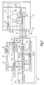
- an electrically passive opto-acoustic liquid quantity gauging system 10 for an aircraft is shown.
- the electrically passive acoustic fuel quantity gauging system shown generally at 10 includes a tank 12 which supports an acoustic source 14 and an acoustic detector 16, and encloses liquid fuel 20.
- the source 14 transmits acoustic output pulses 18 through still fuel 20′ enclosed by stillwell 26 to the liquid-air interface 22 from which acoustic reflection pulses 24 are reflected to acoustic detector 16.
- the stillwell 26 is supported by the tank 12 so that the pulses 18 and 24 travel through still fuel 20′ which is less turbulent in flight than is the portion of fuel 20 which is outside of the stillwell 26.
- Stillwell 26 supports reference reflector 26′. Fuel flows freely into and out of the stillwell 26 through aperture 28.
- the source 14 preferably includes a metal member 30 having a rounded or semispherical (concave or convex) shape supported to allow flexion of the rounded portion.
- a metal member 30 having a rounded or semispherical (concave or convex) shape supported to allow flexion of the rounded portion.
- at least a portion of the surface of the metal member 30 is nonreflective and black.
- Optical pulser 32 pulses high intensity light through optical fibre 34 to the plate 30 which rapidly flexes thereby transmitting acoustic pulses 18.
- the pulser 32 is preferably a pulsed laser, pulsed laser diode, Q-switched laser or optically pumped Q-switched laser.
- the optical source 36 transmits light through optical fibre 38 to acoustic detector 16. Reflected acoustic pulses 24 impinge upon detector 16.
- the detector 16 is preferably a loop 40 in optical fibre 38.
- the fibre 38 may be a single mode or multimode optical fibre.
- the output portion 42 of fibre 38 channels the light to optical detector 44.
- the optical fibre 34, 38 and 42 extend through connectors 38′ and 39 ⁇ and are protected by shielding 39.
- Detector 44 is connected to signal conditioning electronics 46 by electrical conductor 48.
- Signal conditioning electronics 46 is connected by electrical conductor 50 to the optical pulser 32.
- Opto-acoustic signal conditioner 58 includes pulser source 36, detector 44 and signal conditioning electronics 46.
- Signal conditioning electronics 46 includes analog to digital (A/D) converter 60 which is connected by electrical conductor 48 to detector 44, and by electrical conductor 62 to microprocessor 64.
- Microprocessor 64 sends and receives signals from memory 68 through electrical conductor 66.
- Microprocessor 64 sends digital signals through conductor 70 to D/A converter 72.
- D/A converter 72 sends analog signals through electrical conductor 74 to display 76.
- Power supply 78 supplies electrical power through electrical conductor 80 to display 76.
- Power supply 78 supplies electrical power through electrical conductor 82 to optical pulser 32.
- Electrical conductor 84 is connected to power supply 78 which supplies electrical power to optical source 36.
- Power supply 78 supplies electrical power through electrical conductor 86 to A/D converter 60 and to the other components of signal conditioner 58 through connections not shown.
- the detector 44 which is preferably a photodetector, receives electromagnetic radiation, such as light, from the output portion 42 of optical fibre 38. It will be understood that any type of physical movement of the optical fibre 38, such as slight bending, in response to impact of the reflected acoustic pulses, will have an effect upon the light transmitted therethrough.
- Various parameters (or properties) of the light can be detected, such as back scattering sites, discontinuities, attenuation, and the like.
- the movement of the optical fibre caused by the impact of the returning acoustic waves causes changes in the properties of the light signal travelling within the optical fibre.
- Such changes in the properties of the light in the output portion of optical fibre 42 form optical information which is converted to electrical digital form in A/D converter 60 and fed into the microprocessor 64.
- the fuel quantity in tank 12 is determined in microprocessor 64 and signals representative of fuel quantity are displayed by display 70.
- the microprocessor 64 may send further signals to the optical pulser 32 to control the starting time of the acoustic wave pulses 18.
- the time required for an acoustic wave pulse to travel to the reflector 26′ (a known distance) and be reflected therefrom and travel to the receiver (a known distance) is measured.
- the time required for an acoustic wave pulse to travel to and be reflected from the upper surface of the fuel is then measured.
- the level of the liquid is then accurately determined using the speed of sound in the fuel and the time required for the acoustic wave pulse to travel to and from the upper surface of the fuel.
- the fuel quantity and density are inferred from information stored in memory 68 about the volume of the tank 12 when filled to several levels and the speed of sound in the fuel and the speed of sound in the fuel determined from the measurement of the time for sound to travel the known distance to and from the reference reflector all as disclosed in above-mentioned US-PS-4 677 305.
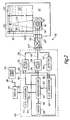
- the electrically passive acoustic fuel quantity gauging system 110 includes a tank 112 which supports acoustic source 114 and an acoustic detector 116.
- the acoustic source 114 transmits acoustic output pulses 118 through the portion 120′ of liquid fuel 120 enclosed by stillwell 126 to the liquid-air interface 122 from which acoustic reflection pulses 124 are reflected to acoustic detector 116.
- the stillwell 126 is supported by the tank 112 so that the pulses 118 and 124 travel through fuel 120′ which is less turbulent in flight than is fuel 120 which is outside of the stillwell 126.
- Stillwell 126 supports reference reflector 126′. Fuel flows freely into and out of the stillwell 126 through aperture 128.
- the source 114 preferably includes a metal member 130 having a rounded or semispherical (concave or convex) shape supported to allow flexion of the rounded portion.
- a metal member 130 having a rounded or semispherical (concave or convex) shape supported to allow flexion of the rounded portion.
- at least a portion of the surface of the metal member 130 is nonreflective and black.
- Optical pulser 132 pulses high intensity light through optical fibre 134 to the plate 130 which rapidly flexes thereby transmitting acoustic pulses 118.
- the pulser 132 is preferably a pulsed laser, pulsed laser diode, Q-switched laser or optically pumped Q-switched laser.
- the optical source 136 transmits light through optical fibre 138 to acoustic detector 116. Reflected acoustic pulses 124 impinge upon detector 116.
- the detector 116 is preferably a loop 140 in optical fibre 138.
- the fibre 138 may be a single mode or multimode.
- the output portion 142 of fibre 138 channels the light to optical detector 144.
- the optical fibre 134, 138 and 142 extend through connectors 139′ and 139 ⁇ and are protected by shielding 139.
- Detector 144 is connected to signal conditioning electronics 146 by electrical conductor 148.
- Signal conditioning electronics 146 is connected by electrical conductor 150 to high intensity optical pulser 132.
- Opto-acoustic signal conditioner 158 includes pulser source 136, detector 144 and signal conditioning electronics 146.
- Signal conditioning electronics 146 includes analog to digital (A/D) converter 160 which is connected by electrical conductor 148 to detector 144, and by electrical conductor 162 to microprocessor 164.
- Microprocessor 164 sends and receives signals from memory 168 through electrical conductor 166.
- Microprocessor 164 sends digital signal through conductor 170 to D/A converter 172.
- D/A converter 172 sends analog signals through electrical conductor 174 to display 176.
- Power supply 178 supplies electrical current through electrical Conductor 180 to display 176.
- Power supply 178 supplies electrical current through electrical conductor 182 to optical pulser 132.
- Power supply 178 is connected through electrical conductor 184 to optical source 136 and through electrical conductor 186 to A/D converter 169.
- the optical detector 144 which is preferably a photodetector, receives electromagnetic radiation, such as light from the output portion 142 of optical fibre 138. As explained in relation to Figure 1, any type of physical movement of the optical fibre 138, such as slight bending, will have an effect upon the light transmitted therethrough. Various parameters (or properties) of the light can be detected, such as back scattering sites, discontinuities, attenuation, and the like.
- Such effects on the light in optical fibre 138 result from the physical movement of the reflected acoustic waves which impact on, and result in the movement of, the optical fibre in acoustic detector 116.
- the optical information is converted to digital form in A/D converter 160 and fed into the microprocessor 164.
- Fuel quantity measurement signals from the microprocessor 164 are displayed by display 170. Movement of the acoustic detector 116 is monitored by following the corresponding changes in the parameters of the light passing through the fibre 138, which are detected by optical detector 144 and processed in the microprocessor 164.
- the microprocessor 164 may send further signals to the optical pulser 132 to control the starting time of the acoustic wave pulses 118.
- the metal member 130 in the acoustic source 114 is an optical absorber which absorbs the energy of the light pulses transmitted through the optical fibre 134 to the absorber from the optical pulser 132.
- the optical energy is converted to heat in the absorber which undergoes a rapid expansion to generate an acoustic wave pulse 118.
- the wave pulse 118 propagates upwardly to the surface of the liquid and a reflected wave pulse 124 is reflected downward from the liquid-air interface.
- the acoustic detector 116 (which may be a fibre-optic hydrophone) detects the reflected wave pulse 124.
- the liquid level is determined as a function of the acoustic pulse propagation time in the manner explained in connection with Fig. 1.
- the liquid level may be measured by detecting the change in the intensity of the light transmitted through fibre 138. Instead, the change in the polarization state of the transmitted light is monitored. Another possibility is to use interferometrics.
- Tanks in which liquid quantity may be measured using the systems disclose may be made of metal sheeting, polymeric (organic or inorganic), composite or other suitable material.
- Preferred organic polymeric materials include thermoplastic and thermoset polymers. These materials may include a matrix of metal, for example aluminium, thermoplastic such as polyetherether ketone (PEEK), thermoset polymer or ceramic.
- a preferred composite structure includes high strength filaments or fibres in a polymeric matrix such as a crosslinked epoxy or maleinide.
- Epoxy resins are well established for use in making high performance composite structures which include high strength fibre.
- Preferred fibre materials are metal, glass, boron, carbon, graphite, continuous or chopped, or the like, such as disclosed in US-PS-4 656 208 (Chu et al). Structures made of these composites can weigh considerably less than their metal counterparts of equivalent strength and stiffness.
- the tanks may be fabricated as disclosed in US-PS-4 581 086 (Gill et al, assigned to Hercules Incorporated).
- Helical applicators may be used to deposit a ply or plies of continuous filaments into the form of the tank as disclosed in US-PS-4 519 869 (Gill et al, assignee, Hercules Incorporated).
- multiphase epoxy thermosets having rubber within a disperse phase may be used to make tanks, as disclosed in US-PS-4 680 078 (Bard assigned to Hercules Incorporated).
- Optical fibres and transceivers may be embedded in or attached to these tanks during fabrication. Attachment to the tanks of the optical fibres transceivers after construction may be carried out using the same or a different matrix material than is used to fabricate the underlying tanks.
- compositions which may be used to make tanks include poly(aryl-acetylene) as disclosed in US-PS-4 070 333, US-PS-4 097 460, and US-PS-4 144 218.
- US-PS-4 656 208 discloses thermosetting epoxy resin compositions and thermo-sets therefrom.
Landscapes
- Physics & Mathematics (AREA)
- Electromagnetism (AREA)
- General Physics & Mathematics (AREA)
- Acoustics & Sound (AREA)
- Thermal Sciences (AREA)
- Fluid Mechanics (AREA)
- Optics & Photonics (AREA)
- Engineering & Computer Science (AREA)
- Multimedia (AREA)
- Measurement Of Levels Of Liquids Or Fluent Solid Materials (AREA)
- Measuring Volume Flow (AREA)
- Measurement Of Mechanical Vibrations Or Ultrasonic Waves (AREA)
Claims (21)
- Verfahren zum Aussenden von akustischen Wellen in einem eine Flüssigkeit (20; 120) enthaltenden Tank (12;112) mit einem in der Flüssigkeit (20; 120) positionierten Wandler (30; 130) zum Erzeugen akustischer Energie, dadurch gekennzeichnet, daß der Wandler ein flexibles Glied (30; 130) ist, und durch den Schritt des Durchspeisens elektromagnetischer Strahlung durch eine Lichtleitfaser (34; 134) von außerhalb des Tanks und in ein Auftreffen auf das flexible Glied (30; 130), um zu bewirken, daß das Glied (30; 130) als Reaktion auf ein solches Auftreffen schwingt und akustische Energie aussendet.
- Verfahren nach Anspruch 1, dadurch gekennzeichnet, daß das flexible Glied (30; 130) durch diesem durch die auftreffende elektromagnetische Strahlung mitgeteilte Wärme zur Bewegung veranlaßt wird.
- Verfahren nach Anspruch 1 oder 2, gekennzeichnet durch den Schritt des Bewirkens, daß die ausgesandte akustische Energie auf ein Ausgabewandelglied (16; 116) auftrifft, das durch Erzeugen einer entsprechenden Ausgabe reagiert.
- Verfahren nach Anspruch 3, dadurch gekennzeichnet, daß das Ausgabewandelglied (38; 42; 138; 142) ein bewegliches Ausgabeglied ist.
- Verfahren nach Anspruch 4, dadurch gekennzeichnet, daß das bewegliche Ausgabeglied (38; 42; 138; 142) die besagte entsprechende Ausgabe durch Modulieren weiterer elektromagnetischer Energie erzeugt.
- Verfahren nach Anspruch 5, dadurch gekennzeichnet, daß der Schritt des Modulierens der weiteren elektromagnetischen Energie mittels einer zweiten Lichtleitfaser (38; 42; 138; 142) ausgeführt wird, wobei ein Teil derselben das bewegliche Ausgabeglied darstellt.
- Verfahren nach einem der vorhergehenden Ansprüche, dadurch gekennzeichnet, daß die elektromagnetische Strahlung sichtbares Licht ist.
- Verfahren nach einem der Ansprüche 1 bis 6, dadurch gekennzeichnet, daß die elektromagnetische Strahlung Infrarotstrahlung ist.
- Verfahren nach Anspruch 6, dadurch gekennzeichnet, daß die elektromagnetische Strahlung in der ersterwähnten Lichtleitfaser (34; 134) Infrarotstrahlung und die elektromagnetische Strahlung in der zweiten Lichtleitfaser (38; 138) sichtbares Licht ist.
- Verfahren nach einem der vorhergehenden Ansprüche, gekennzeichnet durch den Schritt des Bewirkens, daß die ausgesandte akustische Energie von der Oberfläche (22; 122) der Flüssigkeit (20; 120) im Tank (12; 112) reflektiert wird, und des Bestimmens der Menge von Flüssigkeit (20; 120) im Tank (12; 112) in Abhängigkeit von der Laufzeit der akustischen Energie zu und von der Flüssigkeitsoberfläche (22; 122), der vorbestimmten Übertragungsgeschwindigkeit akustischer Energie in der Flüssigkeit (20; 120) und den Abmessungen des Tanks (12; 112).
- Verfahren nach Anspruch 3, gekennzeichnet durch den Schritt des Bewirkens, daß die ausgesandte akustische Energie die Flüssigkeit (20; 120) im Tank (12; 112) zur Oberfläche (22; 122) der Flüssigkeit (20; 120) im Tank (12; 112) durchläuft, so daß sie von dieser Oberfläche (22; 122) reflektiert wird, und dadurch, daß der Schritt des Bewirkens, daß die ausgesandte akustische Energie auf das Ausgabewandelglied (16; 116) auftrifft den Schritt des Empfangens der von der besagten Oberfläche (22; 122) der Flüssigkeit reflektierten akustischen Energie und des Bewirkens, daß sie auf das Ausgabewandelglied (16; 116) auftrifft, um die entsprechende Ausgabe zu erzeugen, umfaßt, und durch den Schritt des Bestimmens der Menge von Flüssigkeit (20; 120) im Tank (12; 112) aus der entsprechenden Ausgabe in Abhängigkeit von der Laufzeit der akustischen Energie zu und von der Flüssigkeitsoberfläche (22; 122), der vorbestimmten Übertragungsgeschwindigkeit akustischer Energie in der Flüssigkeit (20; 120) und den Abmessungen des Tanks (12; 112).
- Akustische Wandelanordnung mit einem akustischen Wandler, der in einem eine Flüssigkeit (20; 120) enthaltenden Tank (12; 112) befestigt ist und der bei seiner Erregung das Aussenden akustischer Energie in der Flüssigkeit bewirkt, dadurch gekennzeichnet, daß der akustische Wandler ein flexibles Glied (30; 130) umfaßt, und durch eine Lichtleitfaser (34; 134) zum Einspeisen elektromagnetischer Strahlung in ein Auftreffen auf das flexible Glied (30; 130), um das Glied (30; 130) als Reaktion darauf zum Schwingen und zum Aussenden von akustischer Energie zu veranlassen.
- Anordnung nach Anspruch 12, dadurch gekennzeichnet, daß das flexible Glied (30; 130) dort, wo es erwärmt wird sich biegen kann, und daß die auftreffende elektromagnetische Strahlung das flexible Glied erwärmt.
- Anordnung nach Anspruch 12, dadurch gekennzeichnet, daß das flexible Glied ein für die Aufnahme von Wärme behandeltes gekrümmtes dünnes Glied (30; 130) aus Metall ist.
- Anordnung nach einem der Ansprüche 12 bis 14, gekennzeichnet durch einen auf die vom Wandelglied (30; 130) erzeugte akustische Energie reagierenden Empfangswandler (16; 116) für akustische Energie zur Erzeugung einer entsprechenden Ausgabe.
- Anordnung nach Anspruch 15, dadurch gekennzeichnet, daß der Empfangswandler (16; 116) für akustische Energie eine elektrisch passive Vorrichtung (38, 42) umfaßt, die elektromagnetische Energie führt und dem Auftreffen der akustischen Energie auf diese ausgesetzt ist, wobei ein solches Auftreffen die Modulation der geführten elektromagnetischen Strahlung bewirkt.
- Anordnung nach Anspruch 16, dadurch gekennzeichnet, daß die elektrisch passive Vorrichtung (38, 42) des Empfangswandlers (16; 116) für akustische Energie ein die besagte elektromagnetische Energie führendes bewegliches Glied (38, 42) umfaßt, daß sich als Reaktion auf das Auftreffen der akustischen Energie auf dieses bewegt, wobei ein solches Auftreffen die besagte Modulation der elektromagnetischen Strahlung bewirkt.
- Anordnung nach Anspruch 17, dadurch gekennzeichnet, daß das die elektromagnetische Energie führende bewegliche Glied (38, 42) eine Lichtleitfaser umfaßt.
- Anordnung nach einem der Ansprüche 15 bis 18 und zum Messen der Höhe der Flüssigkeit (20; 120) im Tank (12; 112), dadurch gekennzeichnet, daß das Wandelglied (30; 130) zum Leiten der akustischen Energie auf die Flüssigkeitsoberfläche (22; 122) positioniert ist, daß der Empfangswandler (16; 116) für akustische Energie zum Empfangen der von der besagten Oberfläche (22; 122) reflektierten akustischen Energie positioniert ist, und durch auf die empfangene akustische Energie reagierende Ausgabemittel (58; 158), die die Erzeugung einer die Flüssigkeitshöhe anzeigenden Ausgabe bewirken.
- Anordnung nach Anspruch 19, dadurch gekennzeichnet, daß die Ausgabemittel auf die empfangene akustische Energie reagierende Signalverarbeitungsmittel (46; 146) zum Erzeugen eines entsprechenden elektrischen Signals umfassen, die in Abhängigkeit von diesem elektrischen Signal und von gespeicherten Informationen betreffs der Geschwindigkeit akustischer Energie in der Flüssigkeit (20; 120) und den physikalischen Abmessungen des Tanks (12; 120) die Erzeugung einer der Flüssigkeitsmenge im Tank entsprechenden Ausgabe bewirken.
- Anordnung nach einem der Ansprüche 12 bis 20, dadurch gekennzeichnet, daß die elektromagnetische Strahlung Licht oder Infrarotstrahlung ist.
Applications Claiming Priority (2)
| Application Number | Priority Date | Filing Date | Title |
|---|---|---|---|
| US246103 | 1988-09-19 | ||
| US07/246,103 US4900921A (en) | 1988-09-19 | 1988-09-19 | System and method for opto-acoustic liquid quantity measurement and transducer therefor |
Publications (3)
| Publication Number | Publication Date |
|---|---|
| EP0360449A2 EP0360449A2 (de) | 1990-03-28 |
| EP0360449A3 EP0360449A3 (en) | 1990-06-13 |
| EP0360449B1 true EP0360449B1 (de) | 1994-06-01 |
Family
ID=22929326
Family Applications (1)
| Application Number | Title | Priority Date | Filing Date |
|---|---|---|---|
| EP89308934A Expired - Lifetime EP0360449B1 (de) | 1988-09-19 | 1989-09-04 | Verfahren und Anordnung mit akustischem Wandler |
Country Status (5)
| Country | Link |
|---|---|
| US (1) | US4900921A (de) |
| EP (1) | EP0360449B1 (de) |
| JP (1) | JPH02168119A (de) |
| DE (1) | DE68915666D1 (de) |
| IL (1) | IL91669A0 (de) |
Cited By (2)
| Publication number | Priority date | Publication date | Assignee | Title |
|---|---|---|---|---|
| DE102004053549A1 (de) * | 2004-11-05 | 2006-05-11 | Siemens Ag | Optisches Hydrophon |
| US7974182B2 (en) | 2004-03-31 | 2011-07-05 | British Telecommunications Public Limited Company | Evaluating the position of a disturbance |
Families Citing this family (35)
| Publication number | Priority date | Publication date | Assignee | Title |
|---|---|---|---|---|
| DE3900274A1 (de) * | 1989-01-07 | 1990-07-12 | Basf Ag | Messschaltung zur erfassung von messsignalen |
| EP0601739B1 (de) * | 1992-11-25 | 2001-05-30 | Simmonds Precision Products Inc. | Datenverarbeitungsstrukturen und Methoden |
| US5602540A (en) * | 1993-06-14 | 1997-02-11 | Simmonds Precision Products Inc. | Fluid gauging apparatus with inductive interrogation |
| US5433115A (en) * | 1993-06-14 | 1995-07-18 | Simmonds Precision Products, Inc. | Contactless interrogation of sensors for smart structures |
| US5581248A (en) * | 1993-06-14 | 1996-12-03 | Simmonds Precision Products, Inc. | Embeddable device for contactless interrogation of sensors for smart structures |
| US5515041A (en) * | 1993-06-14 | 1996-05-07 | Simmonds Precision Products Inc. | Composite shaft monitoring system |
| GB9522949D0 (en) * | 1995-11-09 | 1996-01-10 | M & A Packaging Serv Ltd | Fill level measuring |
| US5719329B1 (en) * | 1995-12-28 | 1999-11-16 | Univ Ohio | Ultrasonic measuring system and method of operation |
| US5944687A (en) * | 1996-04-24 | 1999-08-31 | The Regents Of The University Of California | Opto-acoustic transducer for medical applications |
| KR100363929B1 (ko) * | 1997-11-06 | 2002-12-11 | 가부시끼가이샤 도시바 | 산농도 측정 및 자동 제어방법과 장치 |
| US6659957B1 (en) | 1998-03-05 | 2003-12-09 | Gil M. Vardi | Optical-acoustic imaging device |
| US6502465B1 (en) | 1999-09-27 | 2003-01-07 | Ohio University | Determining gas and liquid flow rates in a multi-phase flow |
| US6404204B1 (en) * | 2000-05-01 | 2002-06-11 | ARETé ASSOCIATES | Sensor and sensor system for liquid conductivity, temperature and depth |
| US7245789B2 (en) | 2002-10-07 | 2007-07-17 | Vascular Imaging Corporation | Systems and methods for minimally-invasive optical-acoustic imaging |
| US7667849B2 (en) | 2003-09-30 | 2010-02-23 | British Telecommunications Public Limited Company | Optical sensor with interferometer for sensing external physical disturbance of optical communications link |
| GB0322859D0 (en) | 2003-09-30 | 2003-10-29 | British Telecomm | Communication |
| GB0421747D0 (en) | 2004-09-30 | 2004-11-03 | British Telecomm | Distributed backscattering |
| EP1794904A1 (de) | 2004-09-30 | 2007-06-13 | British Telecommunications Public Limited Company | Identifizieren oder lokalisieren von wellenleitern |
| GB0427733D0 (en) | 2004-12-17 | 2005-01-19 | British Telecomm | Optical system |
| CA2589792A1 (en) | 2004-12-17 | 2006-06-22 | British Telecommunications Public Limited Company | Assessing a network |
| ATE434774T1 (de) | 2005-03-04 | 2009-07-15 | British Telecomm | Akustooptische modulatoranordnung |
| GB0504579D0 (en) | 2005-03-04 | 2005-04-13 | British Telecomm | Communications system |
| EP1708388A1 (de) | 2005-03-31 | 2006-10-04 | British Telecommunications Public Limited Company | Verfahren zum Mitteilen von Informationen |
| EP1713301A1 (de) | 2005-04-14 | 2006-10-18 | BRITISH TELECOMMUNICATIONS public limited company | Verfahren und Gerät zur Schallübertragung über eine optische Verbindung |
| EP1729096A1 (de) | 2005-06-02 | 2006-12-06 | BRITISH TELECOMMUNICATIONS public limited company | Verfahren und Vorrichtung zur Ermittlung der Stelle einer Störung in einer optischen Faser |
| US7599588B2 (en) * | 2005-11-22 | 2009-10-06 | Vascular Imaging Corporation | Optical imaging probe connector |
| WO2007096579A1 (en) | 2006-02-24 | 2007-08-30 | British Telecommunications Public Limited Company | Sensing a disturbance |
| EP1826924A1 (de) | 2006-02-24 | 2007-08-29 | BRITISH TELECOMMUNICATIONS public limited company | Abtastung einer Störung |
| ATE505861T1 (de) | 2006-02-24 | 2011-04-15 | British Telecomm | Erfassen einer störung |
| US8670662B2 (en) | 2006-04-03 | 2014-03-11 | British Telecommunications Public Limited Company | Evaluating the position of an optical fiber disturbance |
| US7574082B2 (en) * | 2007-03-28 | 2009-08-11 | Verizon Services Organization Inc. | Optical power monitoring with robotically moved macro-bending |
| WO2010039950A1 (en) | 2008-10-02 | 2010-04-08 | Eberle Michael J | Optical ultrasound receiver |
| CN101908437A (zh) * | 2010-07-09 | 2010-12-08 | 江苏港星方能超声洗净科技有限公司 | 液位开关 |
| US10048186B2 (en) | 2016-03-18 | 2018-08-14 | Simmonds Precision Products, Inc. | Optically interfaced fluid density sensor |
| CN111734393A (zh) * | 2020-06-28 | 2020-10-02 | 中国石油天然气股份有限公司 | 一种油井动液面测试装置及操作方法 |
Family Cites Families (6)
| Publication number | Priority date | Publication date | Assignee | Title |
|---|---|---|---|---|
| GB2101404B (en) * | 1981-07-02 | 1984-11-28 | Standard Telephones Cables Ltd | Semiconductor switch device |
| GB2121953B (en) * | 1982-06-10 | 1985-09-04 | Itt Ind Ltd | Improvements in transducers |
| GB8323685D0 (en) * | 1983-09-03 | 1983-10-05 | Gen Electric Co Plc | Monitoring displacement |
| US4677305A (en) * | 1985-06-28 | 1987-06-30 | Simmonds Precision Products, Inc. | Opto-acoustic fuel quantity gauging system |
| GB8530809D0 (en) * | 1985-12-13 | 1986-01-22 | Gen Electric Co Plc | Sensor |
| US4715226A (en) * | 1986-08-15 | 1987-12-29 | Xecutek Corporation | Ultrasonic apparatus for determining the amount of liquid in a container of known volume |
-
1988
- 1988-09-19 US US07/246,103 patent/US4900921A/en not_active Expired - Fee Related
-
1989
- 1989-09-04 DE DE68915666T patent/DE68915666D1/de not_active Expired - Lifetime
- 1989-09-04 EP EP89308934A patent/EP0360449B1/de not_active Expired - Lifetime
- 1989-09-18 JP JP1240288A patent/JPH02168119A/ja active Pending
- 1989-09-18 IL IL91669A patent/IL91669A0/xx unknown
Cited By (2)
| Publication number | Priority date | Publication date | Assignee | Title |
|---|---|---|---|---|
| US7974182B2 (en) | 2004-03-31 | 2011-07-05 | British Telecommunications Public Limited Company | Evaluating the position of a disturbance |
| DE102004053549A1 (de) * | 2004-11-05 | 2006-05-11 | Siemens Ag | Optisches Hydrophon |
Also Published As
| Publication number | Publication date |
|---|---|
| JPH02168119A (ja) | 1990-06-28 |
| EP0360449A3 (en) | 1990-06-13 |
| DE68915666D1 (de) | 1994-07-07 |
| US4900921A (en) | 1990-02-13 |
| EP0360449A2 (de) | 1990-03-28 |
| IL91669A0 (en) | 1990-04-29 |
Similar Documents
| Publication | Publication Date | Title |
|---|---|---|
| US4900921A (en) | System and method for opto-acoustic liquid quantity measurement and transducer therefor | |
| US4922096A (en) | System for monitoring and controlling physical movement | |
| US4677305A (en) | Opto-acoustic fuel quantity gauging system | |
| US4590803A (en) | Acoustic waveguide monitoring | |
| US4734577A (en) | Continuous strain measurement along a span | |
| US4692610A (en) | Fiber optic aircraft load relief control system | |
| US4183007A (en) | Ultrasonic transceiver | |
| US4947693A (en) | Discrete strain sensor | |
| US4269506A (en) | Apparatus for measuring the influence of physical parameters on the length of a path | |
| US3834233A (en) | Apparatus for measuring the level of the contents of a container | |
| HUP9800836A2 (hu) | Eljárás és elrendezés túltöltés megállapítására tartályban lévő folyadék szintmérésekor impulzusfutásidő alapján | |
| US5734623A (en) | Fiber optic sound velocity profiler | |
| HU220827B1 (hu) | Berendezés tartály előre meghatározott töltési szintjének megállapítására és/vagy megfigyelésére | |
| Huang et al. | An optimized lightweight ultrasonic liquid level sensor adapted to the tilt of liquid level and ripple | |
| US20030032529A1 (en) | Remote measuring device for an exercise machine with counterweights | |
| JP4328921B2 (ja) | レーザ距離計及びレーザ距離計を用いたレベル計 | |
| US4952797A (en) | System and method for optically controlled acoustic transmission and reception | |
| US5367175A (en) | Method of measuring liquid level with a thermal interface detection | |
| US3651687A (en) | Ultrasonic micrometer | |
| CN103988060B (zh) | 用于借助光纤传感器检测声波和/或压力波的转换器装置 | |
| US6229762B1 (en) | Acoustic sensor for a point in space | |
| EP1088203A1 (de) | Drahtloser kraftstoffmesser | |
| WO1991019171A1 (en) | Fluid level detector system and apparatus | |
| US5508704A (en) | Method and apparatus for modulating a doppler radar signal | |
| JPH0674995B2 (ja) | 充填状態測定装置 |
Legal Events
| Date | Code | Title | Description |
|---|---|---|---|
| PUAI | Public reference made under article 153(3) epc to a published international application that has entered the european phase |
Free format text: ORIGINAL CODE: 0009012 |
|
| AK | Designated contracting states |
Kind code of ref document: A2 Designated state(s): DE FR GB IT NL SE |
|
| PUAL | Search report despatched |
Free format text: ORIGINAL CODE: 0009013 |
|
| AK | Designated contracting states |
Kind code of ref document: A3 Designated state(s): DE FR GB IT NL SE |
|
| 17P | Request for examination filed |
Effective date: 19901106 |
|
| 17Q | First examination report despatched |
Effective date: 19920410 |
|
| GRAA | (expected) grant |
Free format text: ORIGINAL CODE: 0009210 |
|
| AK | Designated contracting states |
Kind code of ref document: B1 Designated state(s): DE FR GB IT NL SE |
|
| PG25 | Lapsed in a contracting state [announced via postgrant information from national office to epo] |
Ref country code: IT Free format text: LAPSE BECAUSE OF FAILURE TO SUBMIT A TRANSLATION OF THE DESCRIPTION OR TO PAY THE FEE WITHIN THE PRE;WARNING: LAPSES OF ITALIAN PATENTS WITH EFFECTIVE DATE BEFORE 2007 MAY HAVE OCCURRED AT ANY TIME BEFORE 2007. THE CORRECT EFFECTIVE DATE MAY BE DIFFERENT FROM THE ONE RECORDED.SCRIBED TIME-LIMIT Effective date: 19940601 Ref country code: NL Effective date: 19940601 |
|
| REF | Corresponds to: |
Ref document number: 68915666 Country of ref document: DE Date of ref document: 19940707 |
|
| ET | Fr: translation filed | ||
| PG25 | Lapsed in a contracting state [announced via postgrant information from national office to epo] |
Ref country code: SE Effective date: 19940901 |
|
| PG25 | Lapsed in a contracting state [announced via postgrant information from national office to epo] |
Ref country code: DE Effective date: 19940902 |
|
| NLV1 | Nl: lapsed or annulled due to failure to fulfill the requirements of art. 29p and 29m of the patents act | ||
| PLBE | No opposition filed within time limit |
Free format text: ORIGINAL CODE: 0009261 |
|
| STAA | Information on the status of an ep patent application or granted ep patent |
Free format text: STATUS: NO OPPOSITION FILED WITHIN TIME LIMIT |
|
| 26N | No opposition filed | ||
| PGFP | Annual fee paid to national office [announced via postgrant information from national office to epo] |
Ref country code: FR Payment date: 19970703 Year of fee payment: 9 |
|
| PGFP | Annual fee paid to national office [announced via postgrant information from national office to epo] |
Ref country code: GB Payment date: 19970707 Year of fee payment: 9 |
|
| PG25 | Lapsed in a contracting state [announced via postgrant information from national office to epo] |
Ref country code: GB Free format text: LAPSE BECAUSE OF NON-PAYMENT OF DUE FEES Effective date: 19980904 |
|
| GBPC | Gb: european patent ceased through non-payment of renewal fee |
Effective date: 19980904 |
|
| PG25 | Lapsed in a contracting state [announced via postgrant information from national office to epo] |
Ref country code: FR Free format text: LAPSE BECAUSE OF NON-PAYMENT OF DUE FEES Effective date: 19990531 |
|
| REG | Reference to a national code |
Ref country code: FR Ref legal event code: ST |