EP0360456A2 - Vorrichtung zum Ausgeben von Flüssigkeiten - Google Patents
Vorrichtung zum Ausgeben von Flüssigkeiten Download PDFInfo
- Publication number
- EP0360456A2 EP0360456A2 EP89309003A EP89309003A EP0360456A2 EP 0360456 A2 EP0360456 A2 EP 0360456A2 EP 89309003 A EP89309003 A EP 89309003A EP 89309003 A EP89309003 A EP 89309003A EP 0360456 A2 EP0360456 A2 EP 0360456A2
- Authority
- EP
- European Patent Office
- Prior art keywords
- fluid dispenser
- container
- cradle
- wave
- causing
- Prior art date
- Legal status (The legal status is an assumption and is not a legal conclusion. Google has not performed a legal analysis and makes no representation as to the accuracy of the status listed.)
- Withdrawn
Links
Images




Classifications
-
- B—PERFORMING OPERATIONS; TRANSPORTING
- B67—OPENING, CLOSING OR CLEANING BOTTLES, JARS OR SIMILAR CONTAINERS; LIQUID HANDLING
- B67D—DISPENSING, DELIVERING OR TRANSFERRING LIQUIDS, NOT OTHERWISE PROVIDED FOR
- B67D3/00—Apparatus or devices for controlling flow of liquids under gravity from storage containers for dispensing purposes
- B67D3/0012—Apparatus or devices for controlling flow of liquids under gravity from storage containers for dispensing purposes provided with mixing devices
Definitions
- THIS INVENTION relates to a fluid dispenser and more particularly although not exclusively to a fluid dispenser suitable for dispensing pre-mixed and post-mixed beverages such as fruit juices, soups and the like which have a tendency to stratify if left undisturbed for any significant period of time.
- Post-mix beverages are generally supplied to the point of sale in concentrated form and are mixed in a container mounted on or connected to a dispenser. Alternatively they may be mixed immediately prior to being placed in a dispenser. Pre-mix beverages are simply poured into the container ready for dispensing.
- This is known as an open ended system. Any beverage which has a tendency to separate or stratify must be agitated prior to being dispensed.
- Conventional open ended systems use, for example, an impeller, a paddle wheel or pump circulation to effect the agitation and prevent sedimentation. Such systems are described in U S Patents Nos 4610 145, 3664 643 and 4008 832.
- a fluid dispenser comprising a cradle for a fluid container in the form of a flexible bag, to hold the container inclined downwardly to a dispensing end thereof and means for intermittently causing a wave-like motion to the contents of the container.
- the means for causing the wave-like motion can be means for applying pressure to a wall of the flexible bag.
- cradle to be supported at the end remote from the dispensing end on springs or for the cradle to include resilient slings to engage around and support the end of the cradle remote from the dispensing end and for the bag to be contained in substantially rigid housing having a removable panel.
- the invention also provides for means for applying pressure to the bag to be a plate or other suitably shaped member on the end of a rod connected by means for reciprocating the rod which may be manually powered or motor driven and in which the rod is in the form of telescoped members spring located to the extended position.
- Other drives may be used and particular reference is made to solenoid and plunger assemblies as well as electromagnetic arrangements to impart intermittent pressure to a wall of the container.
- Still further features of this invention provide for the pressure applying means to be located above the container towards the dispensing end or below the container towards the end remote from the dispensing end and for the holder to provide means causing the container to be narrowed within its length and preferably about midway of its length.
- the container will preferably be a flexible bag and will be located in the holder with its major dimensions extending over the bottom of the holder.
- a dispenser 1 having adjustable feet 2 standing on a support surface 3.
- the dispenser is constructed around a support frame 4 and generally comprises an upper cabinet 5 and a lower cabinet 6.
- the cabinets have walls 7 formed of a thermally insulating material which serves to insulate the interior of the cabinets from the ambient air.
- a top hinged door 8 forms a front wall to the cabinet, the door having a seal 9 around its periphery.
- the door 8 is also formed from an insulating material.
- Refrigeration coils 10 are shown located within the lower cabinet to ensure that the air temperature within this cabinet can be maintained at a preselected level. It may be preferable to have the refrigeration coils in the upper cabinet in some circumstances.
- a fan may also be included to assist in maintaining constant temperature in the cabinets.
- a plurality of box-like cradles 11 are housed within the lower cabinet. These cradles are preferably pivotally mounted to the support frame through pivotal mounts 12 fitted to the support frame. Stub axles 13 which project laterally out of the lower front of each side of each cradle 11 are engaged with the pivotal mounts 12. Each cradle is thus able to pivot relative to the dispenser frame about an axis of rotation coincident with the axis of the axles 13. The axis of rotation is indicated by letter 'A' in Fig. 1. The rear of the cradles are supported on the upper ends of coil springs 14 mounted on the floor 15 towards the rear of the lower cabinet 6.
- Liquid to be dispensed is situated in containers 17 located in these cradles.
- the containers 17 are flexible bags which collapse as liquid is dispensed obviating the need to vent the bag during dispensing.
- An outlet conduit 18 from each bag passes through an opening in the base of the cradle and through a dispensing control valve 19 which will be described more fully herebelow.
- Disturbing means is provided for the liquid in the containers and this will take the form of a rotatable cranked arm 20 supported by the frame 4 and being either powered manually through a suitable handle outside of the cabinet 6 or, preferably, through a variable speed motor 21 which can conveniently be mounted outside the cabinet.
- the motor 21 can be inside the upper cabinet 5 and the cranked arm 20 driven therefrom through gears, belts or other suitable transmission means (not shown).
- the cranked arm 20 will be designed to drive push rods 22 each terminating at its free end in a plate 23 adapted to contact a substantial portion of the upper surface of the container 17.
- the plate 23 will contact the container 17 preferably adjacent the outlet end of the container.
- each push rod will be a telescoping member 24 suitably spring biased to an extended condition. This will enable the push rod to act effectively on both a full and nearly empty container with the movement applied to the push rod by the cranked arm.
- rocker arms 25 can be made to operate on the rear end of the cradles 11 to lift the rear of the cradles 11 to pivot them about their forward ends.
- a suitable motor 26 driving a camshaft 27 can be used to move the rocker arms 25 in the required manner.
- the compression coil springs 14 will act to increase the degree of tilting of the cradles as the fluid is dispensed from containers held in the cradles.
- the rocking of the cradles 11 or application of pressure to the containers through the plates will preferably be done in an out of phase manner indicated in Fig. 1. This enables a minimum of power to be used to agitate the fluid in the containers. It will be appreciated that the tilting of the cradles 11 ensure that less effort is required to rock the cradles than is necessary if the cradles are normally horizontal. Similarly out of phase pressure on the wall of the container adjacent the outlet ensures the use of little effort to provide the required mixing of the contents of the containers.
- the main purpose of having the cradles tilted is however to ensure proper evacuation of the containers in a simple manner.
- each cradle has, in the front lower edge thereof, an opening 29 through which passes the supply conduit 18 from the container 17 located within the cradle 11.
- the conduits 18 are flexible and are able to withstand the continual rocking of the cradle 11 without rupturing. It is considered important that the cradle be dimensioned such that the containers 17 may lie with their longest dimension substantially normal to the pivot axis. It has been found that this provides the best mixing action.
- the conduits 18 from each container pass through the openings 29 and down through a specially shaped beam 30 which defines the forward edge of the base 15 to the lower cabinet 6.
- the beam 30 is formed in two parts, namely a forward part numbered 30.1 and a rearward part numbered 30.2.
- the rearward part 30.2 of the beam 30 has four rounded vertically aligned slots which align with the openings 29 in the cradle.
- the door 8 seals against the forward face of the forward part of the beam.
- each conduit 18 is shut-off by means of a dispensing device 31 as shown in Fig. 2.
- Each dispensing device 31 has a pivotally mounted plate 32 spring biased towards an anvil 33.
- a bar 34 on the plate is positioned to engage the conduit and crimp the conduit between the bar and anvil. This will provide an effective shut-off for the conduit and will ensure that no bacteria or the like is able to ingress into the container through the conduit. Dispensing of liquid takes place by pushing the plate away from the conduit allowing the liquid to dispense under the action of gravity into a cup 35 or other receptacle.
- pre-mixed beverages such as fruit juice or the like will be supplied in a sealed container in the form of a flexible bag.
- the bag will have an outlet conduit therefor pre-fitted to it.
- the conduit can be inserted into an appropriate female connector just prior to dispensing.
- the entire bag will have been sealed and packaged under sterilized conditions and will preferably have been stored and transported in a frozen condition. Natural fruit juice, if properly prepared and frozen, can be kept for periods of up to six months when frozen. The frozen juice will then be allowed to thaw before it is dispensed.
- the upper cabinet 5 is provided situated above the cradles in which frozen back-up containers may be located prior to dispensing.
- the temperature inside the upper cabinet will be maintained at 4°C or to a lower temperature of about 0.5° C.
- the gradual thawing of the liquid of the back-up containers within the cabinet will enable the temperature within the cabinet to be maintained at 4°C without the refrigeration apparatus being utilized. This will lead to an energy saving.
- the empty container When a container is to be replaced, the empty container will be removed from the cradle and a fresh, thawed container placed in position in the cradle. During change over the disturbing means will be switched off. This can be achieved by having a suitable make and break switch so that when the door is opened the agitator will be automatically swtiched off.
- the conduit from the fresh container will be passed through the slot in beam 30 and down through the dispensing device 31. Once in position, a seal on the free end of the conduit may be broken and agitation and dispensing may commence.
- a seal on the conduit is only broken after the container is properly located in position. This will ensure that the beverage as dispensed will not have come into contact with the air at any stage after packaging. Such an arrangement will also minimise the chances of the contents of the container being tampered with prior to the beverage being dispensed.
- the bag will preferably be engaged by a suitable clamping or restraining member when it is inserted into the cradle.
- This clamping member will be such that the flexible bag will be automatically ripped when it is removed empty from the cabinet. In this way it will be ensured that the bag cannot be re-used.
- the box and container will be slipped in and out of the cradle as required.
- the boxes may be made such that they can be reused.
- existing bag-in-the-box packaging can be adopted for agitated dispensing according to this invention.
- agitation devices It is not essential for the beverages to be dispensed in a closed system from collapsible containers as described herein although this is a preferred form of the invention. Vented containers may be employed.
- One advantage of the agitation devices disclosed herein is that pumping or circulating equipment which has heretofor been employed for agitation but which must regularly be cleaned and sterilized is no longer necessary. The agitation equipment described herein never comes into contact with the liquid itself and thus the same degree of sterilization is not required.
- the containers will be charged with concentrate and be of sufficient volume to enable water or other suitable liquid to be added thereto.
- a suitable filling aperture which may be incorporated in the outlet conduit, will be provided.
- the container may have the diluent liquid added immediately prior to insertion of the container into the cabinet or the container can be manufactured so that it can first be inserted into the cabinet and then filled with the diluent liquid.
- the container in the form of a flexible bag is positioned with its major dimensions over the bottom of the cradle or housing. It is also preferred that the bag be permitted to lie flat in the configuration which it will naturally adopt without lateral constriction. This means that the beverage will have a shallow depth in the dispenser and the wave motion will result in most effective mixing.
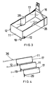
- Fig 4 is illustrated diagrammatically an arrangement where the plurality of cradles 36 are arranged in a superimposed and stepped relationship. This construction will require separate outlet assemblies for each container but this is not considered a disadvantage since the container can if desired be located in separate insulated compartments in the cabinet.
- Figs 5 and 6 illustrate, also diagrammatically alternative drive motor assemblies in place of the usual electric motor drive described above.
- the drive motor consists of a solenoid 37 and plunger 38 assembly.
- the plunger 38 is spring loaded to return to an extended position when the solenoid 37 is not activated.
- the plunger 38 is connected to a crank 39 from which extends a central rod 40.
- This rod 40 is supported in suitable bearings (not shown) and carries lever arms 41 terminating in bag engaging plates 42.
- the lever arms will be offset from each other so the effort will be applied to only one bag 43 at a time. This construction can be made at lower cost than one using a conventional variable speed electric motor.
- Fig 6 illustrtes yet another simple form of motor drive.
- an electro-magnet 44 is located across the container to co-operate with a bar 45 of magnetiseable material positioned on the opposite side of the bag to the electro-magnet 44.
- This bar 45 is carried on suitable guides 46 so that when the electro-magnet 44 is intermittently energised the bar will be drawn towards it and allowed to return along a controlled path and this will result in the wave motion above described being imparted to the contents of the bag.
- the bar 45 can be lightly spring loaded against the action of the electro-magnet to ensure proper operation of this drive motor arrangement. However this will not usually be necessary as in all cases with the flexible bag inclined towards the outlet the flow of liquid to reach its equilibrium in the bag will tend to ensure that this outlet end of the bag returns to its normal full condition.
- a further drive motor assembly is illustrated for imparting a wave-like motion to the contents of the flexible bag.
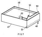
- the cradle 47 is downwardly inclined towards the outlet 48.
- the flexible bag 49 is located in the cradle 47 as in the previous embodiments.
- a plate 50 which extends transversely across the cradle 47 and is hinged at 51 along its lower edge. This plate 50 may thus swing inwardly into the cradle 47 and back towards the end of the cradle. This movement will cause the length of the bag 49 to shorten and lengthen and thus impart the wave-like motion to the contents.
- the solenoid and plunger assembly 52 mounted on the side of the container is an inexpensive and efficient means for oscillating the plate 50.
- FIG 9 there is illustrated a simple means whereby it can be ensure that the bag 49 can be rendered useless after the contents have been dispensed therefrom.
- a gripping member which in Figs 7 and 8 is shown attached to plate 50 but which in other embodiments described can be attached to the holder, is provided. It consists essentially of a disc 53 which has slits 54 equally spaced apart radiating outwardly from the centre. This results in flexible sharp pointed elements 55 which can be flexed axially with respect to the disc 53 to provide an aperture therethrough. While reference to a disc 53 has been made it is to be understood that this term is not to be interpreted as limited to a circular plate. Other shapes are obviously also available.
- the use of the gripping member ensures that an emptied bag 49 cannot be reused.
- the drive assemblies above described can also be used to impart a shaking motion to the cradle and this, with the outlet from the bag held stationary, will also impart a wave-like motion to the contents of the bag.
Landscapes
- Engineering & Computer Science (AREA)
- Mechanical Engineering (AREA)
- Closures For Containers (AREA)
- Devices For Dispensing Beverages (AREA)
Applications Claiming Priority (2)
| Application Number | Priority Date | Filing Date | Title |
|---|---|---|---|
| US07/242,169 US4907723A (en) | 1986-03-10 | 1988-09-08 | Fluid dispenser including an arrangement to impart wave-like motion to the store fluid |
| US242169 | 1994-05-13 |
Publications (2)
| Publication Number | Publication Date |
|---|---|
| EP0360456A2 true EP0360456A2 (de) | 1990-03-28 |
| EP0360456A3 EP0360456A3 (de) | 1990-07-04 |
Family
ID=22913725
Family Applications (1)
| Application Number | Title | Priority Date | Filing Date |
|---|---|---|---|
| EP89309003A Withdrawn EP0360456A3 (de) | 1988-09-08 | 1989-09-06 | Vorrichtung zum Ausgeben von Flüssigkeiten |
Country Status (3)
| Country | Link |
|---|---|
| EP (1) | EP0360456A3 (de) |
| IL (1) | IL91495A0 (de) |
| ZA (1) | ZA896453B (de) |
Cited By (9)
| Publication number | Priority date | Publication date | Assignee | Title |
|---|---|---|---|---|
| WO2002030807A1 (en) * | 2000-10-13 | 2002-04-18 | Mark Bedard | Juice dispensing apparatus |
| US6634783B2 (en) * | 2001-08-09 | 2003-10-21 | Vitality Beverages, Inc. | Apparatus for agitating a fluid suspension |
| FR2872802A1 (fr) * | 2004-07-08 | 2006-01-13 | Oreal | Distributeur de doses d'un produit fluide |
| WO2006006058A3 (en) * | 2004-07-08 | 2006-05-04 | Oreal | A dispenser for dispensing doses of a fluid |
| US7080755B2 (en) | 2004-09-13 | 2006-07-25 | Michael Handfield | Smart tray for dispensing medicaments |
| WO2007124847A1 (de) * | 2006-05-03 | 2007-11-08 | Sartorius Stedim Biotech Gmbh | Behälteranordnung mit einem behälter mit flexibler wandung |
| EP2374541A1 (de) * | 2010-04-06 | 2011-10-12 | Symbion Medical Systems Sàrl | Einweg-Ausgabekartusche für medizinische Testgeräte |
| WO2014137682A1 (en) * | 2013-03-05 | 2014-09-12 | The Coca-Cola Company | Beverage dispensing system |
| CN108946642A (zh) * | 2018-08-02 | 2018-12-07 | 温州扬翼轻工机械有限公司 | 一种智能式恒温移动式液体输送车 |
Family Cites Families (5)
| Publication number | Priority date | Publication date | Assignee | Title |
|---|---|---|---|---|
| US2336438A (en) * | 1942-03-06 | 1943-12-07 | Scovill Manufacturing Co | Apparatus for mixing powdered materials |
| US3132848A (en) * | 1961-05-22 | 1964-05-12 | Garlinghouse Brothers | Quick mixer |
| US3453033A (en) * | 1968-01-12 | 1969-07-01 | Hood & Sons Inc H P | Beverage dispenser cabinet |
| US3667499A (en) * | 1970-05-04 | 1972-06-06 | Sta Rite Industries | Liquid dispensing system |
| EP0237260B1 (de) * | 1986-03-10 | 1989-12-20 | Solly Katz | Ausgeber für Flüssigkeiten |
-
1989
- 1989-08-24 ZA ZA896453A patent/ZA896453B/xx unknown
- 1989-08-31 IL IL91495A patent/IL91495A0/xx unknown
- 1989-09-06 EP EP89309003A patent/EP0360456A3/de not_active Withdrawn
Cited By (26)
| Publication number | Priority date | Publication date | Assignee | Title |
|---|---|---|---|---|
| WO2002030807A1 (en) * | 2000-10-13 | 2002-04-18 | Mark Bedard | Juice dispensing apparatus |
| US6634783B2 (en) * | 2001-08-09 | 2003-10-21 | Vitality Beverages, Inc. | Apparatus for agitating a fluid suspension |
| US6637929B2 (en) * | 2001-08-09 | 2003-10-28 | Vitality Beverages, Inc. | Method for agitating a fluid suspension |
| EP1425087A4 (de) * | 2001-08-09 | 2006-04-26 | Vitality Foodservice Inc | Vorrichtung und verfahren zum bewegen einer flüssigen suspension |
| FR2872802A1 (fr) * | 2004-07-08 | 2006-01-13 | Oreal | Distributeur de doses d'un produit fluide |
| WO2006006058A3 (en) * | 2004-07-08 | 2006-05-04 | Oreal | A dispenser for dispensing doses of a fluid |
| US7751933B2 (en) | 2004-09-13 | 2010-07-06 | Michael Handfield | Smart tray for dispensing medicaments |
| US7908030B2 (en) | 2004-09-13 | 2011-03-15 | Michael Handfield | Smart tray for dispensing medicaments |
| US7440818B2 (en) | 2004-09-13 | 2008-10-21 | Animatronics, Inc. | Medicament tray inventory system and method |
| US7630790B2 (en) | 2004-09-13 | 2009-12-08 | Michael Handfield | Medicament inventory system and method |
| US7721914B2 (en) | 2004-09-13 | 2010-05-25 | Michael Handfield | Container for dispensing medicaments having a compressible medium therein |
| US7735683B2 (en) | 2004-09-13 | 2010-06-15 | Michael Handfield | Smart tray for dispensing medicaments |
| US7080755B2 (en) | 2004-09-13 | 2006-07-25 | Michael Handfield | Smart tray for dispensing medicaments |
| US7844362B2 (en) | 2004-09-13 | 2010-11-30 | Michael Handfield | Method of intelligently dispensing medicaments |
| US7860603B2 (en) | 2004-09-13 | 2010-12-28 | Michael Handfield | Medicaments container with medicament authentication mechanism |
| US8112175B2 (en) | 2004-09-13 | 2012-02-07 | Michael Handfield | Methods and apparatus for medicament tracking |
| US7909207B2 (en) | 2004-09-13 | 2011-03-22 | Michael Handfield | Smart tray for dispensing medicaments |
| US7917246B2 (en) | 2004-09-13 | 2011-03-29 | Michael Handfield | Lockable medicament dispensing apparatus with authentication mechanism |
| US7949426B2 (en) | 2004-09-13 | 2011-05-24 | Michael Handfield | Medicaments container with display component |
| WO2007124847A1 (de) * | 2006-05-03 | 2007-11-08 | Sartorius Stedim Biotech Gmbh | Behälteranordnung mit einem behälter mit flexibler wandung |
| US10322388B2 (en) | 2006-05-03 | 2019-06-18 | Sartorius Stedim Biotech Gmbh | Container system with one container with a flexible partition |
| EP2374541A1 (de) * | 2010-04-06 | 2011-10-12 | Symbion Medical Systems Sàrl | Einweg-Ausgabekartusche für medizinische Testgeräte |
| JP2011221019A (ja) * | 2010-04-06 | 2011-11-04 | Symbion Medical Systems Societe A Responsabilite Limitee | 医薬分析計器装備用の使い捨て分配カートリッジ |
| WO2014137682A1 (en) * | 2013-03-05 | 2014-09-12 | The Coca-Cola Company | Beverage dispensing system |
| US9045260B2 (en) | 2013-03-05 | 2015-06-02 | The Coca-Cola Company | Beverage dispensing system |
| CN108946642A (zh) * | 2018-08-02 | 2018-12-07 | 温州扬翼轻工机械有限公司 | 一种智能式恒温移动式液体输送车 |
Also Published As
| Publication number | Publication date |
|---|---|
| ZA896453B (en) | 1990-05-30 |
| IL91495A0 (en) | 1990-04-29 |
| EP0360456A3 (de) | 1990-07-04 |
Similar Documents
| Publication | Publication Date | Title |
|---|---|---|
| US4907723A (en) | Fluid dispenser including an arrangement to impart wave-like motion to the store fluid | |
| US11272721B2 (en) | Systems and methods for distributing and dispensing chocolate | |
| US6516625B2 (en) | Juice dispensing apparatus | |
| US8777057B2 (en) | Pressure vessel, system and/or method for dispensing a comestible mixture | |
| US9994437B2 (en) | Apparatus, systems and methods for dispensing drinks, food, and other liquids | |
| EP0360456A2 (de) | Vorrichtung zum Ausgeben von Flüssigkeiten | |
| US8820094B1 (en) | Thermoelectric wine bag cooler/dispenser | |
| US5803312A (en) | Manually operable postmix juice dispenser and disposable concentrate package therefor | |
| CN110393812B (zh) | 灭菌装置以及自动售卖机 | |
| EP3998868B1 (de) | Vorrichtung zur herstellung und ausgabe von gekühlten lebensmittelprodukten | |
| US3608786A (en) | Portable auger lift cubed ice dispenser | |
| WO1996006540A1 (en) | Method and apparatus for disinfecting solid substance or solid substance containing liquid substance, and container therefor | |
| GB2146620A (en) | Beverage dispensing systems | |
| WO2000059821A1 (en) | Dispensing machine | |
| CN87102876A (zh) | 液体分配器 | |
| JPH03275492A (ja) | 液状又は半液状物質の保存分配方法及びその装置 | |
| RU2781821C1 (ru) | Раздаточный кран для автомата по продаже жидкости | |
| US20240268409A1 (en) | Systems and methods for distributing and dispensing chocolate | |
| CA2323591C (en) | Juice dispensing apparatus | |
| WO2018078554A1 (en) | System for dispensing refrigerated products | |
| US3994214A (en) | Apparatus for heating foodstuffs or other substances | |
| CN107105703A (zh) | 单个冷冻饮品分配器 | |
| JP3268510B2 (ja) | 軟性容器内の液体混合手段付きの液体定量抽出ディスペンサー | |
| JP2002034458A (ja) | コーヒー豆ブレンド装置 | |
| MXPA00004034A (de) |
Legal Events
| Date | Code | Title | Description |
|---|---|---|---|
| PUAI | Public reference made under article 153(3) epc to a published international application that has entered the european phase |
Free format text: ORIGINAL CODE: 0009012 |
|
| AK | Designated contracting states |
Kind code of ref document: A2 Designated state(s): AT BE CH DE ES FR GB GR IT LI LU NL SE |
|
| PUAL | Search report despatched |
Free format text: ORIGINAL CODE: 0009013 |
|
| AK | Designated contracting states |
Kind code of ref document: A3 Designated state(s): AT BE CH DE ES FR GB GR IT LI LU NL SE |
|
| 17P | Request for examination filed |
Effective date: 19910102 |
|
| 17Q | First examination report despatched |
Effective date: 19920826 |
|
| STAA | Information on the status of an ep patent application or granted ep patent |
Free format text: STATUS: THE APPLICATION IS DEEMED TO BE WITHDRAWN |
|
| 18D | Application deemed to be withdrawn |
Effective date: 19930106 |