EP0360465B1 - Système de bandeau de rive et de sous-rive pour bâtiments - Google Patents
Système de bandeau de rive et de sous-rive pour bâtiments Download PDFInfo
- Publication number
- EP0360465B1 EP0360465B1 EP89309100A EP89309100A EP0360465B1 EP 0360465 B1 EP0360465 B1 EP 0360465B1 EP 89309100 A EP89309100 A EP 89309100A EP 89309100 A EP89309100 A EP 89309100A EP 0360465 B1 EP0360465 B1 EP 0360465B1
- Authority
- EP
- European Patent Office
- Prior art keywords
- soffit
- fascia
- flange
- flanges
- groove
- Prior art date
- Legal status (The legal status is an assumption and is not a legal conclusion. Google has not performed a legal analysis and makes no representation as to the accuracy of the status listed.)
- Expired - Lifetime
Links
- 210000003195 fascia Anatomy 0.000 title claims description 50
- 239000000463 material Substances 0.000 description 7
- 238000010276 construction Methods 0.000 description 5
- 239000004033 plastic Substances 0.000 description 4
- 229920003023 plastic Polymers 0.000 description 4
- 239000003000 extruded plastic Substances 0.000 description 2
- 230000000284 resting effect Effects 0.000 description 2
- 239000002023 wood Substances 0.000 description 2
- 230000006978 adaptation Effects 0.000 description 1
- 239000004568 cement Substances 0.000 description 1
- 239000002131 composite material Substances 0.000 description 1
- 230000008030 elimination Effects 0.000 description 1
- 238000003379 elimination reaction Methods 0.000 description 1
- 238000001125 extrusion Methods 0.000 description 1
- 238000009434 installation Methods 0.000 description 1
- 238000004519 manufacturing process Methods 0.000 description 1
- 239000002184 metal Substances 0.000 description 1
- 229920011532 unplasticized polyvinyl chloride Polymers 0.000 description 1
- 238000009423 ventilation Methods 0.000 description 1
Images



Classifications
-
- E—FIXED CONSTRUCTIONS
- E04—BUILDING
- E04D—ROOF COVERINGS; SKY-LIGHTS; GUTTERS; ROOF-WORKING TOOLS
- E04D13/00—Special arrangements or devices in connection with roof coverings; Protection against birds; Roof drainage ; Sky-lights
- E04D13/15—Trimming strips; Edge strips; Fascias; Expansion joints for roofs
- E04D13/158—Trimming strips; Edge strips; Fascias; Expansion joints for roofs covering the overhang at the eave side, e.g. soffits, or the verge of saddle roofs
Definitions
- This invention relates to a fascia for use in conjunction with various types of soffit in the construction of buildings.
- a typical roof construction for buildings such as houses, at the eaves of the roof the rafters project beyond the wall.
- a vertically extending fascia board is provided along the ends of the rafters and a horizontally extending soffit is provided in the space between the wall and the fascia board.
- the fascia board has been of wood and the soffit has been of a suitable sheet material.
- fascia panels of extruded plastics material as in for example WO 83/02636, either to replace conventional wooden fascia boards or to be used over such boards.
- the fascia panels may even be combined with other components such as a gutter system which can be formed on the outer face of the panel.
- a gutter system which can be formed on the outer face of the panel.
- the soffit itself may now be of many different types. It may, for example, be a plain sheet of wood or of a cement based composite material. Alternatively it may comprise a series of interlocking plastics panels.
- the groove along the fascia panel is designed to receive, and in some cases interlock with, the particular soffit with which it is to be used.
- an extruded fascia panel for use at the eaves of a roof, having adjacent its lower edge a first longitudinally extending flange, a second longitudinally extending flange spaced upwardly from the first so as to define a first groove for receiving the edge of a soffit, and a third longitudinally extending flange spaced upwardly from the second so as to define a second groove for receiving the edge of a soffit, the spacing between the first and second flanges at least in part being substantially different from the spacing between the second and third flanges, at least one of the first and second flanges being resilient to permit variation of said spacing between them, at least one of the second and third flanges being resilient to permit variation of said spacing between them, and each of said first and second grooves being provided with interlocking means for engagement with a soffit if desired.
- the interlocking means could be in the form of a downwardly extending projection extending adjacent the free edge of each of the second and third flanges, which can engage in a longitudinal groove in a soffit board or interlock with e.g. a flange along a plastics soffit panel.
- the fascia panel can be used in the form above described. However in some cases it may be desired to remove one of the flanges. This could be done by making the flange frangible but in general it could be achieved at the manufacturing stage by extruding the fascia panel with one flange missing.
- the, or each, groove may not be used for soffit location but for other purposes.
- one of the grooves has its minimum spacing defined by a projection extending from one of the respective flanges towards the other. This projection is generally in addition to any projection forming the interlocking means. Where the soffit is to extend perpendicularly to the fascia panel it will rest flat on the projection.
- the projection acting as a fulcrum.
- the projection must be sufficiently great, and must be positioned sufficiently near to the entry to the groove, to permit the desired angle of tilt.
- the projection is positioned on one flange opposite an interlocking means projection on the other.
- Such an arrangement of projections can be of use with single groove fascias, whether of a generally different design to that disclosed herein or resulting from elimination of one of the flanges as mentioned earlier.
- This disclosure encompasses all such fascia panels and of course extends to fascia panels which are parts of other units such as gutter systems.
- the flanges may serve purposes other than locating soffits.
- a flange can receive a clip which enables the fascia panel to be attached to e.g. a conventional wooden fascia board.
- a particularly advantageous possibility is that of using the lower groove to receive the soffit and using the third flange for attachment to a board.
- the fascia panel 1 is the same and is a suitable length of extruded plastics such as UPVC. Along its lower edge it has a first flange 2. Spaced above this by a distance a is a second flange 3 and spaced above this by a distance b is a third flange 4. There are thus defined two grooves 5 and 6 for receiving soffits. The distance a is less than distance b , but in any event the first flange 2 is provided with two relatively thin, vertically projecting, longitudinally extending supports 7 and 8 which thus define the narrowest part of groove 5. Support 7 is at the mouth of the groove 5 and support 8 is positioned inwardly of it. In some arrangements one of the supports 7 or 8 can be omitted and this may facilitate extrusion. One preferred arrangement uses support 7 only.
- Flange 3 has a downwardly projecting, longitudinally extending barb 9 along its outer edge and flange 4 has a similar barb 10. These barbs are intended to interlock with various types of soffit.
- Barb 9 has its point 11 disposed opposite the inner support 8 on flange 2.
- the flanges 3 and 4 are deflectable resiliently.
- a soffit 12 of rigid sheet material is received in groove 5. It extends perpendicularly to the fascia panel and rests on supports 7 and 8. It is kept in place by means of the barb 9 engaging in a longitudinally extending groove 13 in the soffit 12. The flange 3 and barb 9 will have been deflected upwardly as the soffit 12 was pushed into the groove 5 since the space between the point 11 of barb 9, and the support 8 is less than the thickness of the soffit.
- a soffit 14 of thicker sheet material is positioned in groove 5.
- the resilience of flange 3 keeps the barb 9 engaged against the upper surface of the soffit 14, the lower surface resting on supports 7 and 8.
- FIG. 3 there is shown a plastics soffit panel 15 engaged in the upper groove 6.
- the soffit panel 15 has an interlocking region which in use can be used to interlock the panel 15 with a like panel to provide a soffit of appropriate size.
- the interlocking region includes an upwardly directed portion 16 and a return portion 17.
- the soffit panel 15 rests flat on the upper surface of flange 3 and the free end of the portion 17 interlocks with the barb 10 of flange 4 which is deflected resiliently away from flange 3 to a certain extent.
- FIG 4 shows an installation in which a soffit is inclined upwardly away from the fascia panel 1.
- the soffit 18 is of sheet material with a groove 19. It is received in the groove 5, resting on support 8 which acts as a fulcrum.
- the barb 9 is received in the groove 19 with the downwardly and outwardly facing flat part 20 of the barb engaging the bottom of the groove 19 in the soffit.
- the angle of this part 20 of the barb 9 can thus set the angle of the soffit. It is possible to have a tilted soffit with a fascia having only support 7, which will act as the fulcrum.
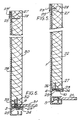
- FIG 5 there is shown a soffit 21 engaged in groove 5 in a manner identical to the arrangement of Figure 1.
- flange 4 is also used, to assist in securing the fascia panel 1 to a conventional wooden fascia board 22 which will generally be part of an existing roof structure which is being modified.
- a metal or plastic clip 23 is provided.
- the clip can be a short item, with a number being used, or can be a long strip.
- This has a groove 24 and fits over flange 4.
- a projection 25 cooperates with the barb 10 to locate the clip 23.
- a nail 26 or like fastener secures the clip 23 to the board 22.
- a further projection 27 is provided on the clip 23 opposite projection 25 but this is optional and need not be provided.
- a clip 23′ identical to clip 23 is used to secure this upper end to the wooden board, the clip 23′ itself being attached to the board by means of a nail 28.
- the upper end of the fascia panel 1 is gripped between projections 25 and 27, the clip being suitably resilient.
- the fascia panel 1 could itself have an inwardly directed flange at its upper edge which could be secured to the top of the board 22. This flange could have apertures to receive fixing nails or the like.
- FIG 6 there is shown a modified type of system.
- a fascia panel 29 is provided which whilst in most respects is identical to that shown in Figure 5, has the third flange 4 missing.
- the fascia panel 29 is attached to a wooden board 30, this being achieved at its upper end by means of clip 23′ as in the arrangement of Figure 5.
- a soffit 31 of rigid sheet material by means of a nail or like fastener 32.
- a further clip 23 ⁇ identical to clips 23′ and 23 (from the arrangement of Figure 5), is then secured to the soffit 31 and board 30 by means of a further nail or like fastener 33.
- the lower end of the fascia panel is then secured to the board/soffit construction by means of flange 3 engaging in the groove 24 of clip 23 ⁇ .
- the barb 9 of flange 3 interlocks with the projection 25 of clip 23 ⁇ .
- Fig. 7 shows an arrangement similar to Figure 6, once again for adaptation of an existing wooden fascia board system.
- the fascia board 34 is connected to clip 23 ⁇ directly by nail 33, without the intervention of a soffit.
- the board 34 is provided with a groove 35 extending along its length which receives a conventional soffit sheet 36 in a known manner.
- fascia panel designs disclosed herein are capable of being used in many contexts with many different types of soffits and constructions.
Landscapes
- Engineering & Computer Science (AREA)
- Architecture (AREA)
- Civil Engineering (AREA)
- Structural Engineering (AREA)
- Building Environments (AREA)
Claims (4)
Applications Claiming Priority (2)
| Application Number | Priority Date | Filing Date | Title |
|---|---|---|---|
| GB888821051A GB8821051D0 (en) | 1988-09-08 | 1988-09-08 | Fascia & soffit system for buildings |
| GB8821051 | 1988-09-08 |
Publications (2)
| Publication Number | Publication Date |
|---|---|
| EP0360465A1 EP0360465A1 (fr) | 1990-03-28 |
| EP0360465B1 true EP0360465B1 (fr) | 1991-09-04 |
Family
ID=10643242
Family Applications (1)
| Application Number | Title | Priority Date | Filing Date |
|---|---|---|---|
| EP89309100A Expired - Lifetime EP0360465B1 (fr) | 1988-09-08 | 1989-09-07 | Système de bandeau de rive et de sous-rive pour bâtiments |
Country Status (3)
| Country | Link |
|---|---|
| EP (1) | EP0360465B1 (fr) |
| DE (1) | DE68900244D1 (fr) |
| GB (1) | GB8821051D0 (fr) |
Families Citing this family (8)
| Publication number | Priority date | Publication date | Assignee | Title |
|---|---|---|---|---|
| AU639096B2 (en) * | 1990-10-03 | 1993-07-15 | Ian Thomas Howe | Panel mounting |
| US5377463A (en) * | 1991-10-25 | 1995-01-03 | Howe Ian T | Panel mounting |
| AU668373B2 (en) * | 1992-01-28 | 1996-05-02 | Ian Thomas Howe | Panel mounting |
| GB2318811B (en) * | 1996-11-01 | 2001-01-10 | Swish Prod | Soffit - fascia roof ventilation |
| GB9706449D0 (en) * | 1997-03-27 | 1997-05-14 | Swish Prod | Decorative soffit-fascia system |
| GB9708900D0 (en) * | 1997-05-02 | 1997-06-25 | Swish Prod | Barge board system |
| AU749038B2 (en) * | 1998-01-30 | 2002-06-20 | Stramit Corporation Pty Limited | Fascia assembly |
| US12565775B2 (en) * | 2024-03-01 | 2026-03-03 | Alpha Aluminum, Inc | Locking soffit |
Family Cites Families (5)
| Publication number | Priority date | Publication date | Assignee | Title |
|---|---|---|---|---|
| US3135070A (en) * | 1960-06-10 | 1964-06-02 | Reynolds Metals Co | Building and roof construction |
| DE1893281U (de) * | 1961-11-15 | 1964-05-21 | Paul Uhl | Ortgang-wetterschutzvorrichtung fuer flache metall- oder bitumenpappe-dacheindeckung. |
| FR2205613B1 (fr) * | 1972-11-09 | 1975-11-07 | Plastival Sa | |
| US3874131A (en) * | 1973-05-03 | 1975-04-01 | Reynolds Metals Co | Building construction |
| US4580374A (en) * | 1982-01-29 | 1986-04-08 | Quinnell Geoffrey C | Soffit and fascia system |
-
1988
- 1988-09-08 GB GB888821051A patent/GB8821051D0/en active Pending
-
1989
- 1989-09-07 EP EP89309100A patent/EP0360465B1/fr not_active Expired - Lifetime
- 1989-09-07 DE DE8989309100T patent/DE68900244D1/de not_active Expired - Fee Related
Also Published As
| Publication number | Publication date |
|---|---|
| EP0360465A1 (fr) | 1990-03-28 |
| GB8821051D0 (en) | 1988-10-05 |
| DE68900244D1 (de) | 1991-10-10 |
Similar Documents
| Publication | Publication Date | Title |
|---|---|---|
| US4580374A (en) | Soffit and fascia system | |
| US5352154A (en) | Metal roof ventilation system | |
| US20030029097A1 (en) | Siding and overhang attachment system | |
| US6378256B1 (en) | Wall closure for roof systems | |
| US4844651A (en) | Fastening clip | |
| US4135342A (en) | Insulated metal roofing and siding system | |
| US7748191B2 (en) | Cladding apparatus and methods | |
| US5003743A (en) | Panel support member and support arrangement | |
| US5737881A (en) | Interlocking roof system | |
| US5735084A (en) | Fascia-soffit combination | |
| US5004191A (en) | Rain gutter support and mounting bracket | |
| US4641473A (en) | Clip construction for wall arrangement | |
| WO1985003965A1 (fr) | Montages de support | |
| US5577360A (en) | Slate mounting system | |
| WO2004081307A2 (fr) | Systeme de fixation et d'alignement de bardage et de porte-a-faux | |
| JP3031597B2 (ja) | インターロック式建築用パネル | |
| EP0360465B1 (fr) | Système de bandeau de rive et de sous-rive pour bâtiments | |
| US6138418A (en) | Soffit and fascia system | |
| US4251972A (en) | Interior ceiling panel support | |
| US4506479A (en) | Roof or wall covering and mounting member for a gutter bracket | |
| US20060144002A1 (en) | Cladding element | |
| WO2003014493A1 (fr) | Elements de fixation a ressort allonges pour entrepots | |
| US5303521A (en) | Fascia panel | |
| GB2276644A (en) | Roof or wall cladding supporting system | |
| GB2118991A (en) | Ventilating roofs |
Legal Events
| Date | Code | Title | Description |
|---|---|---|---|
| PUAI | Public reference made under article 153(3) epc to a published international application that has entered the european phase |
Free format text: ORIGINAL CODE: 0009012 |
|
| AK | Designated contracting states |
Kind code of ref document: A1 Designated state(s): BE DE FR GB NL SE |
|
| 17P | Request for examination filed |
Effective date: 19900515 |
|
| 17Q | First examination report despatched |
Effective date: 19901203 |
|
| GRAA | (expected) grant |
Free format text: ORIGINAL CODE: 0009210 |
|
| AK | Designated contracting states |
Kind code of ref document: B1 Designated state(s): BE DE FR GB NL SE |
|
| PG25 | Lapsed in a contracting state [announced via postgrant information from national office to epo] |
Ref country code: SE Effective date: 19910904 Ref country code: NL Effective date: 19910904 Ref country code: BE Effective date: 19910904 |
|
| REF | Corresponds to: |
Ref document number: 68900244 Country of ref document: DE Date of ref document: 19911010 |
|
| EN | Fr: translation not filed | ||
| PG25 | Lapsed in a contracting state [announced via postgrant information from national office to epo] |
Ref country code: FR Effective date: 19920124 |
|
| NLV1 | Nl: lapsed or annulled due to failure to fulfill the requirements of art. 29p and 29m of the patents act | ||
| PG25 | Lapsed in a contracting state [announced via postgrant information from national office to epo] |
Ref country code: DE Effective date: 19920602 |
|
| PLBE | No opposition filed within time limit |
Free format text: ORIGINAL CODE: 0009261 |
|
| STAA | Information on the status of an ep patent application or granted ep patent |
Free format text: STATUS: NO OPPOSITION FILED WITHIN TIME LIMIT |
|
| 26N | No opposition filed | ||
| REG | Reference to a national code |
Ref country code: FR Ref legal event code: ST |
|
| REG | Reference to a national code |
Ref country code: GB Ref legal event code: IF02 |
|
| PGFP | Annual fee paid to national office [announced via postgrant information from national office to epo] |
Ref country code: GB Payment date: 20030903 Year of fee payment: 15 |
|
| PG25 | Lapsed in a contracting state [announced via postgrant information from national office to epo] |
Ref country code: GB Free format text: LAPSE BECAUSE OF NON-PAYMENT OF DUE FEES Effective date: 20040907 |
|
| GBPC | Gb: european patent ceased through non-payment of renewal fee |
Effective date: 20040907 |