EP0360772A2 - Système pour la pose verticale de câbles - Google Patents
Système pour la pose verticale de câbles Download PDFInfo
- Publication number
- EP0360772A2 EP0360772A2 EP89850297A EP89850297A EP0360772A2 EP 0360772 A2 EP0360772 A2 EP 0360772A2 EP 89850297 A EP89850297 A EP 89850297A EP 89850297 A EP89850297 A EP 89850297A EP 0360772 A2 EP0360772 A2 EP 0360772A2
- Authority
- EP
- European Patent Office
- Prior art keywords
- profiles
- boxes
- locking
- profile
- swung
- Prior art date
- Legal status (The legal status is an assumption and is not a legal conclusion. Google has not performed a legal analysis and makes no representation as to the accuracy of the status listed.)
- Granted
Links
Images

Classifications
-
- H—ELECTRICITY
- H02—GENERATION; CONVERSION OR DISTRIBUTION OF ELECTRIC POWER
- H02G—INSTALLATION OF ELECTRIC CABLES OR LINES, OR OF COMBINED OPTICAL AND ELECTRIC CABLES OR LINES
- H02G3/00—Installations of electric cables or lines or protective tubing therefor in or on buildings, equivalent structures or vehicles
- H02G3/02—Details
- H02G3/04—Protective tubing or conduits, e.g. cable ladders or cable troughs
- H02G3/0493—Service poles
Definitions
- the present invention relates to a system for vertical cable laying and the arrangement of cable outlets etc. the system including channel profiles or columns containing the cables, with sockets or junction boxes mounted on the columns.
- So-called cable columns are known which are intended for taking down or containing power supply cables, data and telephone lines and for having mounted on them various outlets, usually utilizing installation boxes mounted outside the column itself.
- the column may comprise a plurality of assembled profiles.
- the object of the present invention is to provide an improved system of the kind mentioned in the introduction, whereby the above mentioned desires are satisfied.
- the system thus includes two mutually opposed, parallel and spaced channel profiles, which are joined to each other along two opposing longitudinal edges via connection means.
- the respective profile is pivotably connected to said connection means, so that the profile is pivotable relative the latter about a pivot axis which is parallel to the longitudinal axis of the profile and preferably at least substantially coincides with said longitudinal edge of the profile.
- outlet or junction boxes are mounted in the space between the profiles, the bottoms of the boxes facing towards the side of this space where the pivot axes are, preferably at least substantially at the plane containing these axes.
- the opposing access side of the boxes is intended for being closed by a socket, a lid or the like, and is preferably at least substantially in the plane containing the other two opposing longitudinal edges of the profiles.
- the sides of the profiles facing towards each other and the walls of the boxes are provided with openings allowing cable laying between the interiors of the profiles and boxes.
- locking means are arranged for locking the profiles against pivoting movement, when the latter have been swung inwards from an open, outwardly swung position towards each other for meeting up with boxes lying between them.
- the boxes are preferably parallelepipedic, the sides of the profiles facing towards each other in the inwardly swung, closed position engaging against contiguous box sides, so that a closed, secure and symmetric configuration is obtained. It will be understood that two or more boxes can also be placed in parallel side by side between the profiles, if a wider distance between the latter can be accepted or is desirable.
- the system includes means for closing those parts of the open sides which are not closed by a contiguous box when the profiles are in their swung-in position.
- closure means can include closure plates, the respective profile having to advantage guide grooves at both longitudinal opening edges for receiving the opposing longitudinal edges of a closure plate.
- One or more closure plates can, for example, thus be easily thrust into place from above and downwards.
- connection means can advantageously include at least one plate, extending between the profiles and preferably also constituting a base for attaching boxes. It will be understood that a plate of this kind only needs to be arranged where a box is to be mounted, although it is naturally conceivable to have one or more plates along the entire length of the profile. In the latter case, these plates constitute a whole "bottom” in the channel-shaped space between the profiles. In the former case, the plates advantageously have a size corresponding to the box or boxes which are to be attached to them. The plates then form a partial "bottom" where boxes are mounted.
- connection means may also comprise means for fastening the system in accordance with the invention to ceilings or floors, a wall or a building column.
- the locking means for locking the profiles in their inwardly swung, closed position include to advantage a locking plate, the size of which corresponds to the cross section between the profiles in their swung-in position and which is provided with locking elements, preferably in the form of hooked projections intended to co-act with the profiles to give a locking effect when the locking plate is arranged between the profiles with its plane perpendicular to the longitudinal direction of the profiles.
- the locking elements of the plate are to advantage arranged for co-action with the guide grooves of the profiles, whereby the locking plate can be inserted sloping between the mutually swung-together profiles, and thereafter be swung to its locking position with the locking elements engaging in the guide grooves.
- the locking plate simultaneously serves an intermediate wall in the channel space between the profiles, and this wall can also terminate an underlying box arrangement, as will be understood.
- the locking elements can also constitute stops for closure plates mounted above them in the guide grooves of the profiles.
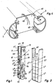
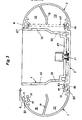
- FIG. 1 - 5 The system in accordance with the invention, illustrated in Figures 1 - 5 includes as main parts two parallel, vertical profiles, 1, 3 which are pivotably connected to each other via connection plates 5 (Figure 3), and junction boxes 7 mounted on the respective plates 5.
- the profiles 1, 3 which are made from aluminium, have a semicircular cross section and are symmetrically implemented at their respective longitudinal edges 9, 10. Inside the respective profile there is a longitudinal partition wall 11 dividing the interior of the profile into two longitudinal channels 12 and 13. The partition wall 11 is somewhat unsymmetrically arranged to give channels 12 and 13 of different sizes.
- the profiles 1, 3 are identically implemented, it will be seen from Figure 3 that one profile is reversed in relation to the other so that equally as great channels 12 and 13, respectively, are facing towards each other.
- the profiles 1, 3 have an inwardly directed longitudinal bead 15, in which there are two longitudinal guide grooves 17 and 19, as well as a substantially cylindrical, longitudinal, rounded-bottom groove 21.
- the groove 17 faces inwardly towards the space between the profiles and the groove 19 faces towards the interior of the profile, at an angle of 90 degrees in relation to the groove 17.
- the groove 21 is further in than the groove 17 and is reached through the latter.
- connection plate 5 has a width determining the distance between the profiles 1, 3 and which is equal to the width of the box 7.
- the plate 5 On either side, the plate 5 has a pivot projection 23 with an outer, substantially cylindrical portion 25, corresponding to the groove 21 and intended for being mounted therein for achieving a pivoting joint between the plate 5 and the adjacent profile 1 or 3.
- the pivotability is illustrated in more detail to the left in Figure 3.
- the box 7 is mounted with its bottom 29 directly on the plate 5, utilizing screws 31.
- the side walls of the box have suitable openings allowing communication between the interior of the box and the channels 12 and 13. Such openings can be arranged as indicated at 33 and 35, for example.
- a locking plate 41 is utilized for locking the profiles in their swung-in positions, and its function is schematically illustrated in Figure 4.
- the locking plate is rectangular and corresponds to the cross section of the space between the profiles, when these are in their swung-in position.
- the locking plate 41 has four hook-shaped locking projections 43, projecting from both sides of the plate and with the hooks facing outwards from each other. The hooks are intended to engage in the guide groove 19 on the profiles 1, 3, when the locking plate 41 is put into place perpendicular to the longitudinal direction of the profiles.
- the locking plate 41 can be inserted slopingly in the space between the profiles, the locking hooks 43 then lying outside the guide grooves 19.
- the locking plate is then swung to its locking position, as illustrated by the arrow 45 in Figure 4, the hooks go into locking engagement with the guide grooves 19.
- FIG. 1 there is illustrated an example of a ready-erected system complete with equipment and in accordance with the invention.
- the undermost box 71 has a lower data outlet 51 and an upper telephone outlet 52.
- the outlets, which are flush with the front longitudinal edges of the profiles are connected to respective lines 53, 54, which are taken down through channel 13 of profile 1.
- the intermediate box 72 has a lower outlet 55 mounted on a lid, and which is connected to a line 56 taken down through the channel 12 of profile 1.
- the uppermost box 73 has dual mains current outlets 57, 58, which are connected to respective cables 59, 60 taken down through the channels 12 and 13, resp., of the profile 3.
- reference numeral 67 indicates a connection means which is also a fastener, whereby the system can be fastened in a desired position, e.g. against a wall or a building column.
- Figure 2 there is schematically illustrated how a system in accordance with the invention can be built up with double the number of junction boxes in relation to what is shown in Figure 1.
- FIG. 5 there is schematically illustrativelyed an example of the configuration of a junction box 7 and how its opening can be closed off in different ways with the aid of a lid, sunk-in outlets and exteriorly mounted outlets.
Landscapes
- Engineering & Computer Science (AREA)
- Architecture (AREA)
- Civil Engineering (AREA)
- Structural Engineering (AREA)
- Laying Of Electric Cables Or Lines Outside (AREA)
- Electrical Discharge Machining, Electrochemical Machining, And Combined Machining (AREA)
- Lifting Devices For Agricultural Implements (AREA)
- Connection Or Junction Boxes (AREA)
- Internal Circuitry In Semiconductor Integrated Circuit Devices (AREA)
- Forklifts And Lifting Vehicles (AREA)
- Details Of Indoor Wiring (AREA)
- Installation Of Indoor Wiring (AREA)
- Light Guides In General And Applications Therefor (AREA)
- Electric Cable Installation (AREA)
Priority Applications (1)
| Application Number | Priority Date | Filing Date | Title |
|---|---|---|---|
| AT89850297T ATE98059T1 (de) | 1988-09-19 | 1989-09-12 | Verfahren zum vertikalen kabelverlegen. |
Applications Claiming Priority (2)
| Application Number | Priority Date | Filing Date | Title |
|---|---|---|---|
| SE8803312 | 1988-09-19 | ||
| SE8803312A SE460161B (sv) | 1988-09-19 | 1988-09-19 | System foer nedfoering av ledningar |
Publications (3)
| Publication Number | Publication Date |
|---|---|
| EP0360772A2 true EP0360772A2 (fr) | 1990-03-28 |
| EP0360772A3 EP0360772A3 (fr) | 1991-05-29 |
| EP0360772B1 EP0360772B1 (fr) | 1993-12-01 |
Family
ID=20373382
Family Applications (1)
| Application Number | Title | Priority Date | Filing Date |
|---|---|---|---|
| EP89850297A Expired - Lifetime EP0360772B1 (fr) | 1988-09-19 | 1989-09-12 | Système pour la pose verticale de câbles |
Country Status (6)
| Country | Link |
|---|---|
| EP (1) | EP0360772B1 (fr) |
| AT (1) | ATE98059T1 (fr) |
| DE (1) | DE68911089T2 (fr) |
| DK (1) | DK168103B1 (fr) |
| NO (1) | NO174030C (fr) |
| SE (1) | SE460161B (fr) |
Cited By (2)
| Publication number | Priority date | Publication date | Assignee | Title |
|---|---|---|---|---|
| US6751913B2 (en) | 2001-05-18 | 2004-06-22 | The Wiremold Company | Vertical wall structure with electrical service |
| FR3023673A1 (fr) * | 2014-07-09 | 2016-01-15 | Decelect | Colonne multireseaux |
Families Citing this family (1)
| Publication number | Priority date | Publication date | Assignee | Title |
|---|---|---|---|---|
| DE102008021811A1 (de) * | 2008-03-12 | 2009-09-17 | Wesemann Gmbh & Co. | Vorrichtung zum Installieren von Versorgungsleitungen |
Family Cites Families (2)
| Publication number | Priority date | Publication date | Assignee | Title |
|---|---|---|---|---|
| CA987612A (en) * | 1974-01-10 | 1976-04-20 | Electrovert Ltd. | Indoor service pole |
| FR2592995B1 (fr) * | 1986-01-15 | 1989-03-03 | Conceptal Sarl | Goulotte de distribution universelle. |
-
1988
- 1988-09-19 SE SE8803312A patent/SE460161B/sv not_active IP Right Cessation
-
1989
- 1989-09-12 AT AT89850297T patent/ATE98059T1/de not_active IP Right Cessation
- 1989-09-12 EP EP89850297A patent/EP0360772B1/fr not_active Expired - Lifetime
- 1989-09-12 DE DE89850297T patent/DE68911089T2/de not_active Expired - Fee Related
- 1989-09-18 DK DK459389A patent/DK168103B1/da not_active IP Right Cessation
- 1989-09-18 NO NO893717A patent/NO174030C/no not_active IP Right Cessation
Cited By (2)
| Publication number | Priority date | Publication date | Assignee | Title |
|---|---|---|---|---|
| US6751913B2 (en) | 2001-05-18 | 2004-06-22 | The Wiremold Company | Vertical wall structure with electrical service |
| FR3023673A1 (fr) * | 2014-07-09 | 2016-01-15 | Decelect | Colonne multireseaux |
Also Published As
| Publication number | Publication date |
|---|---|
| DE68911089T2 (de) | 1994-05-11 |
| SE460161B (sv) | 1989-09-11 |
| DK168103B1 (da) | 1994-02-07 |
| DK459389A (da) | 1990-03-20 |
| ATE98059T1 (de) | 1993-12-15 |
| NO174030C (no) | 1994-03-02 |
| NO893717D0 (no) | 1989-09-18 |
| DE68911089D1 (de) | 1994-01-13 |
| NO893717L (no) | 1990-03-20 |
| NO174030B (no) | 1993-11-22 |
| DK459389D0 (da) | 1989-09-18 |
| EP0360772A3 (fr) | 1991-05-29 |
| EP0360772B1 (fr) | 1993-12-01 |
| SE8803312D0 (sv) | 1988-09-19 |
Similar Documents
| Publication | Publication Date | Title |
|---|---|---|
| US5024614A (en) | Surface accessible wiring system and assembly | |
| US5918433A (en) | Lay-in wireways for a space divider system | |
| US5913787A (en) | Communications conduit connector mounting device | |
| US5722208A (en) | Wall mounting system for electrical devices | |
| US4308418A (en) | Arrangement for hard wiring movable room divider panels | |
| US4899018A (en) | Utility routing system for modular panels | |
| US5870867A (en) | Solid core partition wall | |
| US5277007A (en) | Office panel with top lay-in passageway | |
| US6057509A (en) | Modularized electrical box systems | |
| US7208676B2 (en) | Adjustable mid-panel spillover fitting | |
| US5116235A (en) | Power panel structure | |
| US8183471B2 (en) | Cable raceway | |
| US4967041A (en) | Floor box for access floors | |
| US4540847A (en) | Electrified ceiling system | |
| US5663527A (en) | Stackable conduits with hook and hole clip means | |
| HUT75475A (en) | Cable connection, flooring system, junction box and frame for false flooring systems | |
| US5468908A (en) | Floor box for in-floor service distribution systems | |
| EP0481942A1 (fr) | Cloison de séparation | |
| US6355880B1 (en) | Outlet cover assembly for raceway | |
| US4373111A (en) | Service poles | |
| GB2174254A (en) | Trunking system component | |
| US5129835A (en) | Power panel structure | |
| US4360705A (en) | Panel raceway system corner fitting | |
| EP0360772A2 (fr) | Système pour la pose verticale de câbles | |
| US4808768A (en) | Utility routing system for modular panels |
Legal Events
| Date | Code | Title | Description |
|---|---|---|---|
| PUAI | Public reference made under article 153(3) epc to a published international application that has entered the european phase |
Free format text: ORIGINAL CODE: 0009012 |
|
| AK | Designated contracting states |
Kind code of ref document: A2 Designated state(s): AT BE CH DE ES FR GB GR IT LI LU NL SE |
|
| PUAL | Search report despatched |
Free format text: ORIGINAL CODE: 0009013 |
|
| AK | Designated contracting states |
Kind code of ref document: A3 Designated state(s): AT BE CH DE ES FR GB GR IT LI LU NL SE |
|
| 17P | Request for examination filed |
Effective date: 19910916 |
|
| 17Q | First examination report despatched |
Effective date: 19930202 |
|
| GRAA | (expected) grant |
Free format text: ORIGINAL CODE: 0009210 |
|
| AK | Designated contracting states |
Kind code of ref document: B1 Designated state(s): AT BE CH DE ES FR GB GR IT LI LU NL SE |
|
| PG25 | Lapsed in a contracting state [announced via postgrant information from national office to epo] |
Ref country code: IT Free format text: LAPSE BECAUSE OF FAILURE TO SUBMIT A TRANSLATION OF THE DESCRIPTION OR TO PAY THE FEE WITHIN THE PRE;WARNING: LAPSES OF ITALIAN PATENTS WITH EFFECTIVE DATE BEFORE 2007 MAY HAVE OCCURRED AT ANY TIME BEFORE 2007. THE CORRECT EFFECTIVE DATE MAY BE DIFFERENT FROM THE ONE RECORDED.SCRIBED TIME-LIMIT Effective date: 19931201 Ref country code: FR Effective date: 19931201 Ref country code: AT Effective date: 19931201 Ref country code: CH Effective date: 19931201 Ref country code: BE Effective date: 19931201 Ref country code: ES Free format text: THE PATENT HAS BEEN ANNULLED BY A DECISION OF A NATIONAL AUTHORITY Effective date: 19931201 Ref country code: SE Effective date: 19931201 Ref country code: GR Free format text: LAPSE BECAUSE OF FAILURE TO SUBMIT A TRANSLATION OF THE DESCRIPTION OR TO PAY THE FEE WITHIN THE PRESCRIBED TIME-LIMIT Effective date: 19931201 Ref country code: LI Effective date: 19931201 |
|
| REF | Corresponds to: |
Ref document number: 98059 Country of ref document: AT Date of ref document: 19931215 Kind code of ref document: T |
|
| REF | Corresponds to: |
Ref document number: 68911089 Country of ref document: DE Date of ref document: 19940113 |
|
| REG | Reference to a national code |
Ref country code: CH Ref legal event code: PL |
|
| EN | Fr: translation not filed | ||
| PG25 | Lapsed in a contracting state [announced via postgrant information from national office to epo] |
Ref country code: LU Free format text: LAPSE BECAUSE OF NON-PAYMENT OF DUE FEES Effective date: 19940930 |
|
| PLBE | No opposition filed within time limit |
Free format text: ORIGINAL CODE: 0009261 |
|
| STAA | Information on the status of an ep patent application or granted ep patent |
Free format text: STATUS: NO OPPOSITION FILED WITHIN TIME LIMIT |
|
| 26N | No opposition filed | ||
| PGFP | Annual fee paid to national office [announced via postgrant information from national office to epo] |
Ref country code: DE Payment date: 20010907 Year of fee payment: 13 |
|
| PGFP | Annual fee paid to national office [announced via postgrant information from national office to epo] |
Ref country code: GB Payment date: 20010911 Year of fee payment: 13 |
|
| PGFP | Annual fee paid to national office [announced via postgrant information from national office to epo] |
Ref country code: NL Payment date: 20010930 Year of fee payment: 13 |
|
| REG | Reference to a national code |
Ref country code: GB Ref legal event code: IF02 |
|
| PG25 | Lapsed in a contracting state [announced via postgrant information from national office to epo] |
Ref country code: GB Free format text: LAPSE BECAUSE OF NON-PAYMENT OF DUE FEES Effective date: 20020912 |
|
| PG25 | Lapsed in a contracting state [announced via postgrant information from national office to epo] |
Ref country code: NL Free format text: LAPSE BECAUSE OF NON-PAYMENT OF DUE FEES Effective date: 20030401 Ref country code: DE Free format text: LAPSE BECAUSE OF NON-PAYMENT OF DUE FEES Effective date: 20030401 |
|
| GBPC | Gb: european patent ceased through non-payment of renewal fee |
Effective date: 20020912 |