EP0360780A1 - Bordure détectrice - Google Patents
Bordure détectrice Download PDFInfo
- Publication number
- EP0360780A1 EP0360780A1 EP89890221A EP89890221A EP0360780A1 EP 0360780 A1 EP0360780 A1 EP 0360780A1 EP 89890221 A EP89890221 A EP 89890221A EP 89890221 A EP89890221 A EP 89890221A EP 0360780 A1 EP0360780 A1 EP 0360780A1
- Authority
- EP
- European Patent Office
- Prior art keywords
- light
- sensor strip
- hollow body
- hollow
- hollow profile
- Prior art date
- Legal status (The legal status is an assumption and is not a legal conclusion. Google has not performed a legal analysis and makes no representation as to the accuracy of the status listed.)
- Granted
Links
- 230000004888 barrier function Effects 0.000 claims abstract description 22
- 230000003313 weakening effect Effects 0.000 claims description 4
- 238000012544 monitoring process Methods 0.000 description 4
- 239000000463 material Substances 0.000 description 3
- 230000002441 reversible effect Effects 0.000 description 3
- 239000012528 membrane Substances 0.000 description 2
- 230000001960 triggered effect Effects 0.000 description 2
- 238000004026 adhesive bonding Methods 0.000 description 1
- 239000011248 coating agent Substances 0.000 description 1
- 238000000576 coating method Methods 0.000 description 1
- 230000006835 compression Effects 0.000 description 1
- 238000007906 compression Methods 0.000 description 1
- 239000004020 conductor Substances 0.000 description 1
- 230000006378 damage Effects 0.000 description 1
- 238000011156 evaluation Methods 0.000 description 1
- 210000000056 organ Anatomy 0.000 description 1
- 230000002093 peripheral effect Effects 0.000 description 1
- 229920001296 polysiloxane Polymers 0.000 description 1
- 238000007789 sealing Methods 0.000 description 1
- 230000035945 sensitivity Effects 0.000 description 1
- 238000009423 ventilation Methods 0.000 description 1
Images

Classifications
-
- G—PHYSICS
- G01—MEASURING; TESTING
- G01V—GEOPHYSICS; GRAVITATIONAL MEASUREMENTS; DETECTING MASSES OR OBJECTS; TAGS
- G01V8/00—Prospecting or detecting by optical means
- G01V8/10—Detecting, e.g. by using light barriers
- G01V8/12—Detecting, e.g. by using light barriers using one transmitter and one receiver
- G01V8/14—Detecting, e.g. by using light barriers using one transmitter and one receiver using reflectors
-
- B—PERFORMING OPERATIONS; TRANSPORTING
- B66—HOISTING; LIFTING; HAULING
- B66B—ELEVATORS; ESCALATORS OR MOVING WALKWAYS
- B66B13/00—Doors, gates, or other apparatus controlling access to, or exit from, cages or lift well landings
- B66B13/24—Safety devices in passenger lifts, not otherwise provided for, for preventing trapping of passengers
- B66B13/26—Safety devices in passenger lifts, not otherwise provided for, for preventing trapping of passengers between closing doors
-
- E—FIXED CONSTRUCTIONS
- E05—LOCKS; KEYS; WINDOW OR DOOR FITTINGS; SAFES
- E05F—DEVICES FOR MOVING WINGS INTO OPEN OR CLOSED POSITION; CHECKS FOR WINGS; WING FITTINGS NOT OTHERWISE PROVIDED FOR, CONCERNED WITH THE FUNCTIONING OF THE WING
- E05F15/00—Power-operated mechanisms for wings
- E05F15/40—Safety devices, e.g. detection of obstructions or end positions
- E05F15/42—Detection using safety edges
- E05F15/43—Detection using safety edges responsive to disruption of energy beams, e.g. light or sound
-
- E—FIXED CONSTRUCTIONS
- E05—LOCKS; KEYS; WINDOW OR DOOR FITTINGS; SAFES
- E05F—DEVICES FOR MOVING WINGS INTO OPEN OR CLOSED POSITION; CHECKS FOR WINGS; WING FITTINGS NOT OTHERWISE PROVIDED FOR, CONCERNED WITH THE FUNCTIONING OF THE WING
- E05F15/00—Power-operated mechanisms for wings
- E05F15/40—Safety devices, e.g. detection of obstructions or end positions
- E05F15/42—Detection using safety edges
- E05F15/43—Detection using safety edges responsive to disruption of energy beams, e.g. light or sound
- E05F15/431—Detection using safety edges responsive to disruption of energy beams, e.g. light or sound specially adapted for vehicle windows or roofs
-
- E—FIXED CONSTRUCTIONS
- E05—LOCKS; KEYS; WINDOW OR DOOR FITTINGS; SAFES
- E05F—DEVICES FOR MOVING WINGS INTO OPEN OR CLOSED POSITION; CHECKS FOR WINGS; WING FITTINGS NOT OTHERWISE PROVIDED FOR, CONCERNED WITH THE FUNCTIONING OF THE WING
- E05F15/00—Power-operated mechanisms for wings
- E05F15/40—Safety devices, e.g. detection of obstructions or end positions
- E05F15/42—Detection using safety edges
- E05F15/43—Detection using safety edges responsive to disruption of energy beams, e.g. light or sound
- E05F2015/434—Detection using safety edges responsive to disruption of energy beams, e.g. light or sound with cameras or optical sensors
-
- E—FIXED CONSTRUCTIONS
- E05—LOCKS; KEYS; WINDOW OR DOOR FITTINGS; SAFES
- E05Y—INDEXING SCHEME ASSOCIATED WITH SUBCLASSES E05D AND E05F, RELATING TO CONSTRUCTION ELEMENTS, ELECTRIC CONTROL, POWER SUPPLY, POWER SIGNAL OR TRANSMISSION, USER INTERFACES, MOUNTING OR COUPLING, DETAILS, ACCESSORIES, AUXILIARY OPERATIONS NOT OTHERWISE PROVIDED FOR, APPLICATION THEREOF
- E05Y2900/00—Application of doors, windows, wings or fittings thereof
- E05Y2900/50—Application of doors, windows, wings or fittings thereof for vehicles
- E05Y2900/53—Type of wing
- E05Y2900/55—Windows
Definitions
- the invention relates to a sensor strip in the form of a flexible hollow body for stopping the movement generated by a drive at least one adjustable part when it bumps into an obstacle, in particular a sensor strip arranged on the closing edge of a door, inside which a light barrier is arranged in a hollow profile arranged at the front edge is arranged, in which at least a portion of the light beam runs along the deformable parts of the feeler when bumped, the drive of the moving part being switched off or reversible due to the weakening of the light occurring when bumped.
- Sensor strips are used to stop or reverse a dangerous movement (e.g. that of the closing edge of a gate) if there is an obstacle in the range of motion. In most cases, the sensor strip also fulfills the sealing function in the closed position.
- DE-PS No. 2719438 describes a self-monitoring sensor strip working according to the closed-circuit principle, which has pulled in a strip switch which has a measuring resistor at the outer end via the two conductors. This defines retirement as current flow through the resistor. If the supply line is interrupted, a contact alarm is triggered by an evaluation device. In addition to the great technical effort, this sensor strip has the disadvantage at the ends where the contact connections are and where Gluing the profile this is made watertight to stop working. Furthermore, an application of force which causes a response is only possible from above, ie in one direction and not to the side thereof.
- sensor strips have been developed, in the interior of which a light barrier is arranged, in which at least a portion of the light beam runs along the parts of the sensor strip that are deformable when bumped, the drive of the moving part being driven by the interruption of the light barrier that occurs when the sensor bumps can be switched off or reversible.
- the receiver of the light barrier In the idle state and with undisturbed movement, the receiver of the light barrier is illuminated, so that the circuit of the drive device is not interrupted in this state. If, on the other hand, if there is an obstacle and the sensor strip is deformed, the receiver does not hit light or the lighting is weak, the receiver switches off or reverses the power supply to the drive using conventional, preferably electronic, circuits. Faults in such a safety device will also always have an impact in that the receiver's lighting fails; Such a sensor strip also works in a self-monitoring and intrinsically safe manner.
- Such a sensor strip is described for example in DE-OS 2658660.
- the light beam from the light barrier runs there in a hollow profile with an approximately circular inner cross section.
- the inner cross section of the hollow profile must be fully compressed at least at one point.
- such a complete closure of a tubular body with larger wall thicknesses is not readily possible, so that even with strong compression of the hollow profile, light components can still get from the transmitter to the receiver. It follows from this that the known light barrier works reliably and that in particular the response accuracy, ie the switching of the light barrier, is not satisfactory given a certain predetermined deformation of the sensor strip.
- webs made of flexible material with diaphragm openings for the passage of the light beam are arranged inside the sensor strip according to AT-PS 382 925.
- the invention has for its object to provide a training of the type mentioned, in which even minor deformations, which have not yet triggered a response of the receiver in the conventional training, lead to a reaction of the receiver.
- this object is achieved in that within the elongated hollow body at the end facing away from the support profile, a circular hollow profile is integrated, which forms the front edge, and the wall section of the hollow profile lying in the interior of the hollow body has a slot which serves as a light exit opening when the hollow body is deformed. It is thereby achieved that when the sensor strip is deformed, the hollow profile gapes along the opening, as a result of which a large part of the light which would otherwise be reflected by the inner wall can emerge from the hollow body, thereby causing even slight deformations of the sensor strip to respond to the receiver lead, with a uniform opening of the slot follows, so that unwanted reflections within the hollow profile are avoided.
- the slot can run parallel to the axis. Furthermore, it is advantageous for the stated purpose if the slot extends over the entire length of the light barrier.
- a plurality of hollow profiles equipped with light barriers can be arranged in parallel in a hollow profile.
- the sensor strip can be angled for monitoring peripheral edges or surfaces, a mirror element being arranged in the interior of the hollow profile at every angle lying in the region of the light barrier.
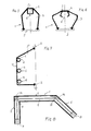
- Fig. 1 shows a longitudinal section through a first embodiment of the sensor strip according to line II of Fig. 2.
- Fig. 2 is a cross section through the sensor strip, namely in the undeformed state thereof.
- 3 and 4 show different forms of deformation of the sensor strip in cross section.
- 5 and 6 illustrate another embodiment of the subject of the invention, etc. in undeformed and in deformed condition.
- Fig. 7 is a cross section through a further embodiment.
- Fig. 8 shows a longitudinal section through an angled embodiment.
- the sensing strip 1 with a sensor strip is designated, which is arranged on a support profile, for example at the front end of a self-closing door.
- the sensing strip 1 has a hollow body 3 in which there is a hollow profile 4 which is arranged on the front edge 5 of the sensing strip 1.
- the hollow body 3 is designed according to FIGS. 1-4 as a closed oval, according to FIGS. 5 and 6 as an open pentagon and according to FIG. 7 as an open square, however any other suitable cross-sectional shape can also be used.
- the hollow profile 4 is located on the front area of the sensing bar 1 in the closing direction and can form part of the front area of the sensing bar.
- the hollow profile 4 thus protrudes into the hollow body 3 and has in its part extending into the interior of the hollow body 3 a slot 6 running in the longitudinal direction.
- the drawing shows a hollow profile that is round in cross section and a hollow profile that is square in cross section, but any other profile shape, such as a polygon or the like, could be used in the same way.
- the inner wall 9 of the hollow profile 4 is designed to reflect light. This light-reflecting property of the inner wall 9 can be achieved in various ways, either by a correspondingly smooth design of the surface or by a special choice of material, for example silicone, or a reflective coating can be applied.
- a hollow body 3 'several, in the present case three, hollow profiles 4 are arranged, the illustrated cross-sectional shapes of hollow body 3' and hollow profiles 4, as already mentioned with regard to the other embodiments, are replaced by any analog cross-sectional shapes can.
- the front edge 5 of the embodiment variant according to FIGS. 1 to 6, which forms the abutting edge 5, is replaced by a wide abutting surface 10, with response to the feed cut-off being achieved even when only one of the hollow profiles 4 is deformed.
- a mirror element 13, 14 is arranged at every angle 11, 12 in the area of the light barrier 7, 8, with which the light beam is undeformed Sensing bar targeted to the receiver 8 is reflected.
- the feeler bar 1 In the idle state, the feeler bar 1 is in the position shown in FIGS. 1 and 2. If a lateral pressure is now exerted on the sensing strip 1, the same deforms as shown in FIG. 3. It can be clearly seen that the slit 6 has a substantially greater width than in the rest position, so that the light exits the slit 6 to a very high degree. By appropriately adjusting the sensitivity of the receiver 8, it can be specified that such a slight deformation of the sensor strip 1 leads to the drive being switched off or reversed.
- the abutting surface 10 could also be formed in the same way when the front edge 5 of the hollow body 3 is deformed (it could also be the abutting surface 10 according to FIG. 7), the mutual angular position of the mirrors 13, 14 is changed, so that the intensity of the light incident on the receiver 8 is also thereby reduced becomes.
- the intrinsic safety of the arrangement according to the invention is achieved in a known manner by using a light barrier with a changeover contact as an output. This switches when the voltage is applied and drops when the light beam is interrupted or the supply line is damaged and the voltage is missing.
Landscapes
- Physics & Mathematics (AREA)
- Life Sciences & Earth Sciences (AREA)
- General Life Sciences & Earth Sciences (AREA)
- General Physics & Mathematics (AREA)
- Geophysics (AREA)
- Geophysics And Detection Of Objects (AREA)
- Power-Operated Mechanisms For Wings (AREA)
- Burglar Alarm Systems (AREA)
Applications Claiming Priority (2)
| Application Number | Priority Date | Filing Date | Title |
|---|---|---|---|
| AT2139/88 | 1988-09-01 | ||
| AT0213988A AT391735B (de) | 1988-09-01 | 1988-09-01 | Fuehlleiste |
Publications (2)
| Publication Number | Publication Date |
|---|---|
| EP0360780A1 true EP0360780A1 (fr) | 1990-03-28 |
| EP0360780B1 EP0360780B1 (fr) | 1991-12-27 |
Family
ID=3528612
Family Applications (1)
| Application Number | Title | Priority Date | Filing Date |
|---|---|---|---|
| EP89890221A Expired - Lifetime EP0360780B1 (fr) | 1988-09-01 | 1989-08-29 | Bordure détectrice |
Country Status (4)
| Country | Link |
|---|---|
| US (1) | US4944116A (fr) |
| EP (1) | EP0360780B1 (fr) |
| AT (1) | AT391735B (fr) |
| DE (1) | DE58900629D1 (fr) |
Cited By (9)
| Publication number | Priority date | Publication date | Assignee | Title |
|---|---|---|---|---|
| FR2663363A1 (fr) * | 1990-06-15 | 1991-12-20 | Roussel Gerard | Dispositif de securite pour porte a fonctionnement automatique. |
| GB2246228A (en) * | 1990-07-20 | 1992-01-22 | Shorrock Ltd | Apparatus for the protection of an external alarm housing |
| EP0501083A1 (fr) * | 1991-03-01 | 1992-09-02 | Daniel Prat | Dispositif de sécurité pour portes basculantes |
| FR2682154A1 (fr) * | 1991-10-03 | 1993-04-09 | Roussel Gerard | Garniture elastiquement deformable pour chant libre de porte. |
| DE9211436U1 (de) * | 1992-08-26 | 1993-12-23 | Siemens AG, 80333 München | Öffnung mit einem motorantriebenen Abdeckelement, z.B. Kfz.-Seitenfenster |
| EP0617186A1 (fr) * | 1992-09-02 | 1994-09-28 | Sumitomo Wiring Systems, Ltd. | Méthode et dispositif d'ouverture et de fermeture de fenêtres de véhicules |
| EP0649967A1 (fr) * | 1993-10-25 | 1995-04-26 | Mewald Gesellschaft M.B.H. | Bordure à interrupteur |
| EP0713949A1 (fr) * | 1994-11-24 | 1996-05-29 | Marantec Antriebs- Und Steuerungstechnik Gmbh & Co., Produktions Kg | Système de sécurité pour la bordure d'une fermeture motorisée d'un passage |
| DE102007001670A1 (de) * | 2007-01-11 | 2008-07-24 | Koenig & Bauer Aktiengesellschaft | Sensoreinrichtung und eine Rotationsdruckmaschine mit mindestens einer Sensoreinrichtung |
Families Citing this family (28)
| Publication number | Priority date | Publication date | Assignee | Title |
|---|---|---|---|---|
| GB9406485D0 (en) * | 1994-03-31 | 1994-05-25 | Standard Prod Ltd | Deformable system |
| US5079417A (en) * | 1991-02-22 | 1992-01-07 | Link Controls, Inc. | Failsafe sensing edge for automatic doors and gates |
| US5228492A (en) * | 1991-10-03 | 1993-07-20 | Jou Ming Sen | Electric rolling steel door safety stopping device |
| US5955854A (en) | 1992-09-29 | 1999-09-21 | Prospects Corporation | Power driven venting of a vehicle |
| US5402075A (en) * | 1992-09-29 | 1995-03-28 | Prospects Corporation | Capacitive moisture sensor |
| US5319217A (en) * | 1992-11-25 | 1994-06-07 | Eastman Kodak Company | Door assembly for cassette autoloader |
| US5426293A (en) * | 1993-04-29 | 1995-06-20 | Miller Edge | Sensing edge having a photoelectric switch positioned therein |
| US5728984A (en) * | 1996-11-20 | 1998-03-17 | Miller Edge, Inc. | Sensing safety edge systems |
| US5743317A (en) * | 1996-07-24 | 1998-04-28 | Rite-Hite Corporation | Impact detection system for industrial doors |
| US5949207A (en) * | 1997-09-03 | 1999-09-07 | Eaton Corporation | Auto window switch and obstacle detect/protect with override |
| WO1999034081A1 (fr) * | 1997-12-24 | 1999-07-08 | Asmo Co., Ltd. | Dispositif d'ouverture et de fermeture automatique |
| JP4245094B2 (ja) * | 1998-02-25 | 2009-03-25 | ダウマル カステリョン メルチョール | 自動車の窓ガラスの自動昇降装置における障害物検知システム |
| US6612357B1 (en) | 1998-04-27 | 2003-09-02 | Rite-Hite Holding Corporation | Impact detection system for industrial doors |
| US6427382B2 (en) | 1999-02-22 | 2002-08-06 | Rytec Corporation | Dual safety-edge for an overhead door |
| US6286257B1 (en) | 1999-02-22 | 2001-09-11 | Rytec Corporation | Overhead door with dual safety-edge |
| US6598648B1 (en) | 1999-03-12 | 2003-07-29 | Rite-Hite Holding Corporation | Industrial door system responsive to an impact |
| US6209262B1 (en) * | 2000-01-27 | 2001-04-03 | Calvin F. Mathis | Obstruction sensing system for a gate |
| US7038414B2 (en) * | 2000-08-03 | 2006-05-02 | Atoma International Corp. | Vehicle closure anti-pinch assembly having a non-contact sensor |
| JP2002238695A (ja) * | 2001-02-15 | 2002-08-27 | Minebea Co Ltd | 乗物用シートのフットレスト装置 |
| JP2002240598A (ja) * | 2001-02-21 | 2002-08-28 | Minebea Co Ltd | 乗物用電動シートおよびその調整方法 |
| WO2002101929A2 (fr) * | 2001-06-08 | 2002-12-19 | Intier Automative Closures, Inc. | Capteur de proximite sans contact |
| US6683296B2 (en) * | 2001-09-13 | 2004-01-27 | Miller Edge, Inc. | Sensor system for controlling movement of a door using a time-delay failure signal |
| DE10212010C1 (de) * | 2002-03-18 | 2003-10-16 | Dorma Gmbh & Co Kg | Dichtung, insbesondere für eine Rauchschutz-Schiebetür |
| US7045764B2 (en) | 2002-10-17 | 2006-05-16 | Rite-Hite Holding Corporation | Passive detection system for detecting a body near a door |
| US20040124972A1 (en) * | 2002-12-27 | 2004-07-01 | Lear Corporation | Window anti-pinch and intrusion alarm |
| US7034682B2 (en) * | 2003-06-20 | 2006-04-25 | Rite-Hite Holding Corporation | Door with a safety antenna |
| US7178289B2 (en) * | 2003-09-12 | 2007-02-20 | B.E.A. Holdings, Inc. | Self-correcting sensor for an entrance |
| DE102007028596B4 (de) * | 2007-04-20 | 2016-01-21 | Klaus Wirth | Thermisch isolierendes Tor |
Citations (2)
| Publication number | Priority date | Publication date | Assignee | Title |
|---|---|---|---|---|
| DE3416546A1 (de) * | 1984-05-04 | 1985-11-07 | Elero Antriebs- und Sonnenschutztechnik GmbH & Co KG, 7312 Kirchheim | Sicherheitsvorrichtung zum anhalten motorisch bewegter gegenstaende |
| AT382925B (de) * | 1985-04-05 | 1987-04-27 | Mewald Franz Ing | Fuehlleiste |
Family Cites Families (7)
| Publication number | Priority date | Publication date | Assignee | Title |
|---|---|---|---|---|
| DE829210C (de) * | 1950-11-21 | 1952-01-24 | Stahl R Fa | Drehbare Aufzugschachttuer |
| DE2432063C3 (de) * | 1974-07-04 | 1979-07-12 | Deutsche Bundesbahn, Vertreten Durch Das Bundesbahn-Zentralamt Minden, 4950 Minden | Einrichtung und Verfahren zur Türschließüberwachung in Nahverkehrsfahrzeugen |
| CH625605A5 (fr) * | 1976-10-02 | 1981-09-30 | Sick Optik Elektronik Erwin | |
| DE2658660C2 (de) * | 1976-12-23 | 1984-07-12 | Erwin Sick Gmbh Optik-Elektronik, 7808 Waldkirch | Sicherheitsvorrichtung an einer automatisch schließenden Schiebetür |
| US4274226A (en) * | 1979-08-06 | 1981-06-23 | Park Mobile, Inc. | Detection of object in path of moving gate |
| DE3107847A1 (de) * | 1980-03-03 | 1982-02-11 | Metallwerk Max Brose Gmbh & Co, 8630 Coburg | Verfahren und vorrichtung zur ueberwachung des schliessvorgangs eines kraftfahrzeugfensters o.dgl. |
| US4482890A (en) * | 1981-01-22 | 1984-11-13 | The Secretary Of State For Defence In Her Britannic Majesty's Government Of The United Kingdom Of Great Britain And Northern Ireland | Weight responsive intrusion detector using dual optical fibers |
-
1988
- 1988-09-01 AT AT0213988A patent/AT391735B/de not_active IP Right Cessation
-
1989
- 1989-08-29 DE DE8989890221T patent/DE58900629D1/de not_active Expired - Fee Related
- 1989-08-29 EP EP89890221A patent/EP0360780B1/fr not_active Expired - Lifetime
- 1989-08-30 US US07/400,557 patent/US4944116A/en not_active Expired - Fee Related
Patent Citations (2)
| Publication number | Priority date | Publication date | Assignee | Title |
|---|---|---|---|---|
| DE3416546A1 (de) * | 1984-05-04 | 1985-11-07 | Elero Antriebs- und Sonnenschutztechnik GmbH & Co KG, 7312 Kirchheim | Sicherheitsvorrichtung zum anhalten motorisch bewegter gegenstaende |
| AT382925B (de) * | 1985-04-05 | 1987-04-27 | Mewald Franz Ing | Fuehlleiste |
Cited By (11)
| Publication number | Priority date | Publication date | Assignee | Title |
|---|---|---|---|---|
| FR2663363A1 (fr) * | 1990-06-15 | 1991-12-20 | Roussel Gerard | Dispositif de securite pour porte a fonctionnement automatique. |
| GB2246228A (en) * | 1990-07-20 | 1992-01-22 | Shorrock Ltd | Apparatus for the protection of an external alarm housing |
| EP0501083A1 (fr) * | 1991-03-01 | 1992-09-02 | Daniel Prat | Dispositif de sécurité pour portes basculantes |
| FR2682154A1 (fr) * | 1991-10-03 | 1993-04-09 | Roussel Gerard | Garniture elastiquement deformable pour chant libre de porte. |
| DE9211436U1 (de) * | 1992-08-26 | 1993-12-23 | Siemens AG, 80333 München | Öffnung mit einem motorantriebenen Abdeckelement, z.B. Kfz.-Seitenfenster |
| EP0617186A1 (fr) * | 1992-09-02 | 1994-09-28 | Sumitomo Wiring Systems, Ltd. | Méthode et dispositif d'ouverture et de fermeture de fenêtres de véhicules |
| US5410227A (en) * | 1992-09-02 | 1995-04-25 | Sumitomo Wiring Systems, Ltd. | Vehicle window opening and closing method and apparatus for detecting an obstacle utilizing sound wave |
| EP0649967A1 (fr) * | 1993-10-25 | 1995-04-26 | Mewald Gesellschaft M.B.H. | Bordure à interrupteur |
| EP0713949A1 (fr) * | 1994-11-24 | 1996-05-29 | Marantec Antriebs- Und Steuerungstechnik Gmbh & Co., Produktions Kg | Système de sécurité pour la bordure d'une fermeture motorisée d'un passage |
| DE102007001670A1 (de) * | 2007-01-11 | 2008-07-24 | Koenig & Bauer Aktiengesellschaft | Sensoreinrichtung und eine Rotationsdruckmaschine mit mindestens einer Sensoreinrichtung |
| DE102007001670B4 (de) * | 2007-01-11 | 2009-11-19 | Koenig & Bauer Aktiengesellschaft | Rotationsdruckmaschine mit mindestens einer Sensoreinrichtung |
Also Published As
| Publication number | Publication date |
|---|---|
| ATA213988A (de) | 1990-05-15 |
| DE58900629D1 (de) | 1992-02-06 |
| US4944116A (en) | 1990-07-31 |
| AT391735B (de) | 1990-11-26 |
| EP0360780B1 (fr) | 1991-12-27 |
Similar Documents
| Publication | Publication Date | Title |
|---|---|---|
| EP0360780B1 (fr) | Bordure détectrice | |
| DE8790065U1 (de) | Sicherheitsvorrichtung, insbesondere für Rolltore | |
| DE3114941C2 (de) | Explosionsverschlußplatte | |
| DE10236648B4 (de) | Schnellaufendes Industrietor mit flexiblem Behang | |
| EP2330271B1 (fr) | Agencement de surveillance de capteur et joint d'une porte porte pivotante coulissante | |
| DE2658660C2 (de) | Sicherheitsvorrichtung an einer automatisch schließenden Schiebetür | |
| EP2818620B1 (fr) | Installation de fenêtre ou de porte automatique | |
| EP1849949A2 (fr) | Surveillance d'arêtes de fermeture secondaires pour portes louvoyantes coulissantes | |
| EP0091607B1 (fr) | Dispositif de sécurité pour éléments de fermeture mobiles, en particulier pour volets de protection de machines d'usinage | |
| EP1856359A1 (fr) | Dispositif de securite destine a des elements de porte, de portail ou de fenetre ainsi que procede associe | |
| DE3416546A1 (de) | Sicherheitsvorrichtung zum anhalten motorisch bewegter gegenstaende | |
| AT382925B (de) | Fuehlleiste | |
| DE19747830C2 (de) | Vorrichtung zur Sicherung der Schließkante eines im wesentlichen translatorisch verstellbaren, motorisch angetriebenen Bauteiles | |
| WO1992021845A1 (fr) | Systeme de securite pour elements de fermeture de passages | |
| DE3840765C1 (fr) | ||
| EP1447512B1 (fr) | Dispositif de sécurité | |
| DE3740326A1 (de) | Sicherheitsvorrichtung fuer motorisch verschwenkbare oder verfahrbare tore, insbesondere tore zum sperren von grundstueckszufahrten | |
| EP2774795A2 (fr) | Profilé creux élastique et porte pivotante intérieure dotée d'un profilé creux élastique | |
| DE102014221953A1 (de) | Sicherheitsanordnung für Schwenktore, Torflügel sowie Schwenktor und Verfahren zum Absichern eines Torflügels eines Schwenktores | |
| EP0953705B1 (fr) | Procédé pour le contrôle cyclique des dispositifs de surveillance dans des systèmes de fermeture de porte | |
| DE4002147C2 (fr) | ||
| DE102004053820B4 (de) | Sensoranordnung für automatische Türanlagen | |
| DE29503907U1 (de) | Sicherheits- oder Funktionskontaktvorrichtung zur Absicherung von Gefahrenzonen | |
| DE3137003A1 (de) | "einklemmschutz fuer automatisch anhebbare fenster in kraftwagen" | |
| EP0649967A1 (fr) | Bordure à interrupteur |
Legal Events
| Date | Code | Title | Description |
|---|---|---|---|
| PUAI | Public reference made under article 153(3) epc to a published international application that has entered the european phase |
Free format text: ORIGINAL CODE: 0009012 |
|
| AK | Designated contracting states |
Kind code of ref document: A1 Designated state(s): CH DE FR GB IT LI SE |
|
| 17P | Request for examination filed |
Effective date: 19900418 |
|
| 17Q | First examination report despatched |
Effective date: 19910123 |
|
| GRAA | (expected) grant |
Free format text: ORIGINAL CODE: 0009210 |
|
| AK | Designated contracting states |
Kind code of ref document: B1 Designated state(s): CH DE FR GB IT LI SE |
|
| REF | Corresponds to: |
Ref document number: 58900629 Country of ref document: DE Date of ref document: 19920206 |
|
| ITF | It: translation for a ep patent filed | ||
| GBT | Gb: translation of ep patent filed (gb section 77(6)(a)/1977) | ||
| ET | Fr: translation filed | ||
| PLBE | No opposition filed within time limit |
Free format text: ORIGINAL CODE: 0009261 |
|
| STAA | Information on the status of an ep patent application or granted ep patent |
Free format text: STATUS: NO OPPOSITION FILED WITHIN TIME LIMIT |
|
| 26N | No opposition filed | ||
| EAL | Se: european patent in force in sweden |
Ref document number: 89890221.8 |
|
| PGFP | Annual fee paid to national office [announced via postgrant information from national office to epo] |
Ref country code: GB Payment date: 19970827 Year of fee payment: 9 Ref country code: FR Payment date: 19970827 Year of fee payment: 9 |
|
| PGFP | Annual fee paid to national office [announced via postgrant information from national office to epo] |
Ref country code: SE Payment date: 19970828 Year of fee payment: 9 |
|
| PGFP | Annual fee paid to national office [announced via postgrant information from national office to epo] |
Ref country code: CH Payment date: 19970922 Year of fee payment: 9 |
|
| PGFP | Annual fee paid to national office [announced via postgrant information from national office to epo] |
Ref country code: DE Payment date: 19971002 Year of fee payment: 9 |
|
| PG25 | Lapsed in a contracting state [announced via postgrant information from national office to epo] |
Ref country code: GB Free format text: LAPSE BECAUSE OF NON-PAYMENT OF DUE FEES Effective date: 19980829 |
|
| PG25 | Lapsed in a contracting state [announced via postgrant information from national office to epo] |
Ref country code: SE Free format text: LAPSE BECAUSE OF NON-PAYMENT OF DUE FEES Effective date: 19980830 |
|
| PG25 | Lapsed in a contracting state [announced via postgrant information from national office to epo] |
Ref country code: LI Free format text: LAPSE BECAUSE OF NON-PAYMENT OF DUE FEES Effective date: 19980831 Ref country code: CH Free format text: LAPSE BECAUSE OF NON-PAYMENT OF DUE FEES Effective date: 19980831 |
|
| REG | Reference to a national code |
Ref country code: CH Ref legal event code: PL |
|
| GBPC | Gb: european patent ceased through non-payment of renewal fee |
Effective date: 19980829 |
|
| PG25 | Lapsed in a contracting state [announced via postgrant information from national office to epo] |
Ref country code: FR Free format text: LAPSE BECAUSE OF NON-PAYMENT OF DUE FEES Effective date: 19990430 |
|
| EUG | Se: european patent has lapsed |
Ref document number: 89890221.8 |
|
| PG25 | Lapsed in a contracting state [announced via postgrant information from national office to epo] |
Ref country code: DE Free format text: LAPSE BECAUSE OF NON-PAYMENT OF DUE FEES Effective date: 19990601 |
|
| REG | Reference to a national code |
Ref country code: FR Ref legal event code: ST |
|
| PG25 | Lapsed in a contracting state [announced via postgrant information from national office to epo] |
Ref country code: IT Free format text: LAPSE BECAUSE OF NON-PAYMENT OF DUE FEES;WARNING: LAPSES OF ITALIAN PATENTS WITH EFFECTIVE DATE BEFORE 2007 MAY HAVE OCCURRED AT ANY TIME BEFORE 2007. THE CORRECT EFFECTIVE DATE MAY BE DIFFERENT FROM THE ONE RECORDED. Effective date: 20050829 |