EP0360780B1 - Fühlleiste - Google Patents
Fühlleiste Download PDFInfo
- Publication number
- EP0360780B1 EP0360780B1 EP89890221A EP89890221A EP0360780B1 EP 0360780 B1 EP0360780 B1 EP 0360780B1 EP 89890221 A EP89890221 A EP 89890221A EP 89890221 A EP89890221 A EP 89890221A EP 0360780 B1 EP0360780 B1 EP 0360780B1
- Authority
- EP
- European Patent Office
- Prior art keywords
- light
- sensing strip
- hollow
- light barrier
- hollow body
- Prior art date
- Legal status (The legal status is an assumption and is not a legal conclusion. Google has not performed a legal analysis and makes no representation as to the accuracy of the status listed.)
- Expired - Lifetime
Links
- 230000004888 barrier function Effects 0.000 claims description 20
- 230000003313 weakening effect Effects 0.000 claims description 4
- 230000002441 reversible effect Effects 0.000 claims description 3
- 238000012544 monitoring process Methods 0.000 description 4
- 239000000463 material Substances 0.000 description 3
- 239000012528 membrane Substances 0.000 description 2
- 230000001960 triggered effect Effects 0.000 description 2
- 238000004026 adhesive bonding Methods 0.000 description 1
- 239000011248 coating agent Substances 0.000 description 1
- 238000000576 coating method Methods 0.000 description 1
- 230000006835 compression Effects 0.000 description 1
- 238000007906 compression Methods 0.000 description 1
- 239000004020 conductor Substances 0.000 description 1
- 230000006378 damage Effects 0.000 description 1
- 230000003292 diminished effect Effects 0.000 description 1
- 238000011156 evaluation Methods 0.000 description 1
- 210000000056 organ Anatomy 0.000 description 1
- 230000002093 peripheral effect Effects 0.000 description 1
- 229920001296 polysiloxane Polymers 0.000 description 1
- 238000007789 sealing Methods 0.000 description 1
- 230000035945 sensitivity Effects 0.000 description 1
- 238000009423 ventilation Methods 0.000 description 1
Images

Classifications
-
- G—PHYSICS
- G01—MEASURING; TESTING
- G01V—GEOPHYSICS; GRAVITATIONAL MEASUREMENTS; DETECTING MASSES OR OBJECTS; TAGS
- G01V8/00—Prospecting or detecting by optical means
- G01V8/10—Detecting, e.g. by using light barriers
- G01V8/12—Detecting, e.g. by using light barriers using one transmitter and one receiver
- G01V8/14—Detecting, e.g. by using light barriers using one transmitter and one receiver using reflectors
-
- B—PERFORMING OPERATIONS; TRANSPORTING
- B66—HOISTING; LIFTING; HAULING
- B66B—ELEVATORS; ESCALATORS OR MOVING WALKWAYS
- B66B13/00—Doors, gates, or other apparatus controlling access to, or exit from, cages or lift well landings
- B66B13/24—Safety devices in passenger lifts, not otherwise provided for, for preventing trapping of passengers
- B66B13/26—Safety devices in passenger lifts, not otherwise provided for, for preventing trapping of passengers between closing doors
-
- E—FIXED CONSTRUCTIONS
- E05—LOCKS; KEYS; WINDOW OR DOOR FITTINGS; SAFES
- E05F—DEVICES FOR MOVING WINGS INTO OPEN OR CLOSED POSITION; CHECKS FOR WINGS; WING FITTINGS NOT OTHERWISE PROVIDED FOR, CONCERNED WITH THE FUNCTIONING OF THE WING
- E05F15/00—Power-operated mechanisms for wings
- E05F15/40—Safety devices, e.g. detection of obstructions or end positions
- E05F15/42—Detection using safety edges
- E05F15/43—Detection using safety edges responsive to disruption of energy beams, e.g. light or sound
-
- E—FIXED CONSTRUCTIONS
- E05—LOCKS; KEYS; WINDOW OR DOOR FITTINGS; SAFES
- E05F—DEVICES FOR MOVING WINGS INTO OPEN OR CLOSED POSITION; CHECKS FOR WINGS; WING FITTINGS NOT OTHERWISE PROVIDED FOR, CONCERNED WITH THE FUNCTIONING OF THE WING
- E05F15/00—Power-operated mechanisms for wings
- E05F15/40—Safety devices, e.g. detection of obstructions or end positions
- E05F15/42—Detection using safety edges
- E05F15/43—Detection using safety edges responsive to disruption of energy beams, e.g. light or sound
- E05F15/431—Detection using safety edges responsive to disruption of energy beams, e.g. light or sound specially adapted for vehicle windows or roofs
-
- E—FIXED CONSTRUCTIONS
- E05—LOCKS; KEYS; WINDOW OR DOOR FITTINGS; SAFES
- E05F—DEVICES FOR MOVING WINGS INTO OPEN OR CLOSED POSITION; CHECKS FOR WINGS; WING FITTINGS NOT OTHERWISE PROVIDED FOR, CONCERNED WITH THE FUNCTIONING OF THE WING
- E05F15/00—Power-operated mechanisms for wings
- E05F15/40—Safety devices, e.g. detection of obstructions or end positions
- E05F15/42—Detection using safety edges
- E05F15/43—Detection using safety edges responsive to disruption of energy beams, e.g. light or sound
- E05F2015/434—Detection using safety edges responsive to disruption of energy beams, e.g. light or sound with cameras or optical sensors
-
- E—FIXED CONSTRUCTIONS
- E05—LOCKS; KEYS; WINDOW OR DOOR FITTINGS; SAFES
- E05Y—INDEXING SCHEME ASSOCIATED WITH SUBCLASSES E05D AND E05F, RELATING TO CONSTRUCTION ELEMENTS, ELECTRIC CONTROL, POWER SUPPLY, POWER SIGNAL OR TRANSMISSION, USER INTERFACES, MOUNTING OR COUPLING, DETAILS, ACCESSORIES, AUXILIARY OPERATIONS NOT OTHERWISE PROVIDED FOR, APPLICATION THEREOF
- E05Y2900/00—Application of doors, windows, wings or fittings thereof
- E05Y2900/50—Application of doors, windows, wings or fittings thereof for vehicles
- E05Y2900/53—Type of wing
- E05Y2900/55—Windows
Definitions
- the invention relates to a sensor strip in the form of a resilient hollow body for stopping the movement generated by a drive at least one adjustable part when it bumps into an obstacle, in particular a sensor strip arranged on the inside of a closing edge of a door, in the interior of which on a side facing away from the support profile
- a light barrier is arranged in the front edge forming the end of the hollow profile, in which at least a portion of the light beam runs along the parts of the sensing strip which are deformable when bumped, the drive of the moving part being able to be switched off or reversed due to the weakening of the light which occurs when bumped.
- Sensor strips are used to stop or reverse a dangerous movement (e.g. that of the closing edge of a gate) if there is an obstacle in the range of motion. In most cases, the sensor strip also fulfills the sealing function in the closed position.
- DE-C-2719438 describes a self-monitoring sensor strip which operates according to the closed-circuit current principle and which has retracted a strip switch which has a measuring resistor at the outer end via the two conductors. This defines retirement as current flow through the resistor. If the supply line is interrupted, a contact alarm is triggered by an evaluation device. Next to the great technical effort, this sensor strip has the disadvantage of no longer functioning at the ends where the contact connections are and where the profile is made waterproof by gluing it together. Furthermore, an application of force which causes a response is only possible from above, ie in one direction and not to the side thereof
- sensor strips have been developed, in the interior of which a light barrier is arranged, in which at least a portion of the light beam runs along the parts of the sensor strip that are deformable when bumped, the drive of the moving part being driven by the interruption of the light barrier that occurs when the sensor bumps can be switched off or reversible.
- the receiver of the light barrier In the idle state and with undisturbed movement, the receiver of the light barrier is illuminated, so that the circuit of the drive device is not interrupted in this state. If, on the other hand, if there is an obstacle and the sensor strip is deformed, the receiver does not hit any light or the lighting is severely diminished, the receiver switches off or reverses the power supply to the drive via conventional, preferably electronic, circuits. Faults in such a safety device will also always have an impact in that the receiver's lighting fails; Such a sensor strip also works in a self-monitoring and intrinsically safe manner.
- Such a sensor strip is described, for example, in DE-A-2658660 or that of AT-B 382925, which forms the preamble of claim 1.
- the light beam from the light barrier runs there in a hollow profile with an approximately circular inner cross section.
- the inner cross section of the hollow profile must be fully compressed at least at one point.
- such a complete closure of a tubular body with larger wall thicknesses is not readily possible, so that even with strong compression of the hollow profile, light components can still get from the transmitter to the receiver. It follows from this that the known light barrier works reliably and that in particular the response accuracy, ie the switching of the light barrier, is not satisfactory given a certain predetermined deformation of the sensor strip.
- the invention has for its object to provide a training of the type mentioned, in which even minor deformations, which have not yet triggered a response of the receiver in the conventional training, lead to a reaction of the receiver.
- this object is achieved in that the wall section of the hollow profile lying inside the hollow body has a slot which serves as a light exit opening when the hollow body is deformed. It is thereby achieved that when the feeler bar is deformed, the hollow profile gapes along the opening, as a result of which a large part of the light, which otherwise reflects from the inner wall would emerge from the hollow body, whereby even slight deformations of the feeler lead to a response of the receiver, with a uniform opening of the slot follows, so that undesirable reflections within the hollow profile are avoided.
- the slot can run parallel to the axis. Furthermore, it is advantageous for the stated purpose if the slot extends over the entire length of the light barrier.
- a plurality of hollow profiles equipped with light barriers can be arranged in parallel in a hollow profile.
- the sensor strip can be angled for monitoring peripheral edges or surfaces, a mirror element being arranged in the interior of the hollow profile at every angle lying in the region of the light barrier.
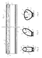
- Fig. 1 shows a longitudinal section through a first embodiment of the sensor strip according to line II of Fig. 2.
- Fig. 2 is a cross section through the sensor strip, namely in the undeformed state thereof.
- 3 and 4 show different forms of deformation of the sensor strip in cross section.
- 5 and 6 illustrate another embodiment of the subject of the invention, etc. in undeformed and in deformed condition.
- Fig. 7 is a cross section through a further embodiment.
- Fig. 8 shows a longitudinal section through an angled embodiment.
- the sensing strip 1 with a sensor strip is designated, which is arranged on a support profile, for example at the front end of a self-closing door.
- the sensing strip 1 has a hollow body 3 in which there is a hollow profile 4 which is arranged on the front edge 5 of the sensing strip 1.
- the hollow body 3 is designed according to FIGS. 1-4 as a closed oval, according to FIGS. 5 and 6 as an open pentagon and according to FIG. 7 as an open square, however any other suitable cross-sectional shape can also be used.
- the hollow profile 4 is located on the front area of the sensing bar 1 in the closing direction and can form part of the front area of the sensing bar.
- the hollow profile 4 thus protrudes into the hollow body 3 and has in its part extending into the interior of the hollow body 3 a slot 6 running in the longitudinal direction.
- the drawing shows a hollow profile that is round in cross section and a hollow profile that is square in cross section, but any other profile shape, such as a polygon or the like, could be used in the same way.
- the inner wall 9 of the hollow profile 4 is designed to reflect light. This light-reflecting property of the inner wall 9 can be achieved in various ways, either by a correspondingly smooth design of the surface or by a special choice of material, for example silicone, or a reflective coating can be applied.
- a hollow body 3 'several, in the present case three, hollow profiles 4 are arranged, the illustrated cross-sectional shapes of hollow body 3' and hollow profiles 4, as already mentioned with regard to the other embodiments, are replaced by any analog cross-sectional shapes can.
- the front edge 5 of the embodiment variant according to FIGS. 1 to 6, which forms the abutting edge 5, is replaced by a wide abutting surface 10, with response to the feed cut-off being achieved even when only one of the hollow profiles 4 is deformed.
- a mirror element 13, 14 is arranged at every angle 11, 12 in the area of the light barrier 7, 8, with which the light beam is undeformed Sensing bar targeted to the receiver 8 is reflected.
- the feeler bar 1 In the idle state, the feeler bar 1 is in the position shown in FIGS. 1 and 2. If a lateral pressure is now exerted on the sensing strip 1, the same deforms as shown in FIG. 3. It can be clearly seen that the slot 6 has a substantially greater width than in the rest position, so that the light exits the slot 6 to a very high degree. By appropriately adjusting the sensitivity of the receiver 8, it can be specified that such a slight deformation of the sensor strip 1 leads to the drive being switched off or reversed.
- the abutting surface 10 could also be formed in the same way when the front edge 5 of the hollow body 3 is deformed (it could also be the abutting surface 10 according to FIG. 7), the mutual angular position of the mirrors 13, 14 is changed, so that the intensity of the light incident on the receiver 8 is also thereby reduced becomes.
- the intrinsic safety of the arrangement according to the invention is achieved in a known manner by using a light barrier with a changeover contact as an output. This switches when the voltage is applied and drops when the light beam is interrupted or the supply line is damaged and the voltage is missing.
Landscapes
- Physics & Mathematics (AREA)
- Life Sciences & Earth Sciences (AREA)
- General Life Sciences & Earth Sciences (AREA)
- General Physics & Mathematics (AREA)
- Geophysics (AREA)
- Geophysics And Detection Of Objects (AREA)
- Power-Operated Mechanisms For Wings (AREA)
- Burglar Alarm Systems (AREA)
Description
- Die Erfindung betrifft eine Fühlleiste in Form eines nachgiebigen Hohlkörpers zum Abstoppen der durch einen Antrieb erzeugten Bewegung mindestens eines verstellbaren Teiles bei dessen Anstoßen an ein Hindernis, insbesondere an der Schließkante eines Tores angeordnete Fühlleiste, in deren Innerem in einem an dem dem Trageprofil abgewandten, die Vorderkante bildenden Ende angeordneten Hohlprofil eine Lichtschranke angeordnet ist, bei welcher zumindest ein Teilstück des Lichtstrahles entlang der beim Anstoßen verformbaren Teile der Fühlleiste verläuft, wobei durch die beim Anstoßen auftretende Schwächung des Lichtes der Antrieb des bewegten Teiles abschalt- bzw. umkehrbar ist.
- Fühlleisten dienen dazu, eine gefahrbringende Bewegung (z.B. jene der Schließkante eines Tores) abzustoppen oder umzukehren, wenn ein Hindernis im Bewegungsbereich ist. In den meisten Fällen erfüllt die Fühlleiste gleichzeitig die Dichtungsfunktion in der geschlossenen Stellung.
- Die bis jetzt handelsüblichen Fühlleisten funktionieren mit einer in einem elastischen Schlauch entstehenden Luftdruckwelle: Beim Ankommen der Leiste an einem Hindernis wird über eine Leitung die Luftdruckwelle an einen Membranschalter weitergegeben. Infolge des geringen erzeugten Luftdruckes sind diese Membranschalter äußerst empfindlich und funktionieren meist nach einiger Zeit nicht mehr, was zu tödlichen Unfällen führen kann.
- Es wurde daher gefordert, diese Fühlleisten selbstüberwachend bzw. eigensicher zu machen, d.h. daß bei Nichtfunktionieren des Systems die gesamte Anlage ausgeschaltet wird.
- In der DE-C-2719438 wird eine nach dem Ruhestromprinzip arbeitende, selbstüberwachende Fühlleiste beschrieben, die einen Streifenschalter eingezogen hat, welcher am äußeren Ende einen Meßwiderstand über die beiden Leiter besitzt. Dadurch ist der Ruhestand als Stromfluß über den Widerstand defininiert. Bei Unterbrechung der Zuleitung erfolgt durch ein Auswertegerät ein Kontaktalarm. Neben dem großen technischen Aufwand hat diese Fühlleiste den Nachteil, an den Enden, wo die Kontaktanschlüsse sind und wo durch Verkleben des Profils dieses wasserdicht gemacht wird, nicht mehr zu funktionieren. Weiters ist eine ein Ansprechen bewirkende Kraftanwendung nur von oben, d.h. in einer Richtung und nicht seitlich dazu, möglich
- Aus der DE-A-3107847 geht eine ähnliche Ausbildung hervor, bei welcher elektromagnetische Wellen, z.B. Lichtwellen, durch ein gekrümmtes, geschlossenes Hohlprofil gesandt werden, wobei die Abnahme der Lichtintensität durch Verringerung des Durchgangsquerschnittes bei Einklemmen von Körperteilen als Regelimpuls für den Antrieb des zu schließenden Fensters dient. Insbesondere dadurch, daß das Hohlprofil, bis auf Entlüftungsöffnungen, geschlossen und mit reflektierendem Material ausgekleidet ist, spricht diese bekannte Ausbildung langsam an, was bereits zu Verletzungen führen kann.
- Um die erwähnten Nachteile zu beseitigen, wurden Fühlleisten entwickelt, in deren Innerem eine Lichtschranke angeordnet ist, bei welcher zumindest ein Teilstück des Lichtstrahles entlang der beim Anstoßen verformbaren Teile der Fühlleiste verläuft, wobei durch die beim Anstoßen auftretende Unterbrechung der Lichtschranke der Antrieb des bewegten Teiles abschaltbar bzw. umkehrbar ist. Im Ruhezustand und bei ungestörter Bewegung wird also der Empfänger der Lichtschranke beleuchtet, so daß in diesem Zustand der Stromkreis der Antriebsvorrichtung nicht unterbrochen wird. Trifft dagegen, bei Auftreten eines Hindernisses und Verformung der Fühlleiste, den Empfanger kein Licht oder ist die Beleuchtung stark geschwächt, schaltet der Empfanger über übliche, vorzugsweise elektronische Schaltkreise die Stromversorgung des Antriebes ab bzw. kehrt diesen um. Störungen einer solchen Sicherheitsvorrichtung werden sich ferner dabei immer dadurch auswirken, daß die Beleuchtung des Empfängers ausfällt; somit arbeitet eine solche Fühlleiste auch selbstüberwachend und eigensicher.
- Eine solche Fühlleiste ist z.B. in der DE-A-2658660 bzw. der des den Oberbegriff anspruchs 1 bildenden AT-B 382925 beschrieben. Der Lichtstrahl der Lichtschranke verläuft dort in einem Hohlprofil mit annähernd kreisrundem Innenquerschnitt. Um den Lichtweg vom Sender zum Empfänger zu unterbrechen, muß der Innenquerschnitt des Hohlprofils zumindest an einer Stelle ganz zusammengedrückt werden. Bekanntlich ist ein solches gänzliches Verschließen eines schlauchartigen Körpers mit größeren Wandstärken nicht ohne weiteres möglich, so daß auch bei starkem Zusammendrücken des Hohlprofils immer noch Lichtanteile vom Sender zum Empfänger gelangen können. Daraus ergibt sich, daß die bekannte Lichtschranke unverläßlich arbeitet und daß insbesondere die Ansprechgenauigkeit, d.h. das Schalten der Lichtschranke bei einer bestimmten vorgegebenen Verformung der Fühlleiste nicht befriedigend ist.
- Um ein zuverlässigeres Unterbrechen des Lichtweges der Lichtschranke beim Überschreiten einer vorgegebenen Verformung der Fühlleiste zu erzielen, sind gemäß der AT-B-382925 im Inneren der Fühlleiste zusätzlich Stege aus nachgiebigem Material mit Blendenöffnungen für den Durchtritt des Lichtstrahles angeordnet.
- All den beschriebenen Ausführungen liegt der Nachteil zugrunde, daß sie zu unempfindlich in der Praxis sind, und zwar jene Systeme, bei denen eine völlige Unterbrechung des Lichtweges erforderlich ist, benötigen eine sehr starke Verformung der Fühlleiste, um zuverlässig den Lichtweg zu unterbrechen, und auch bei jenen Ausbildungen, welche bereits auf eine Schwächung des Lichtes reagieren, bedarf es einer starken Verformung der Fühlleiste, da nämlich aufgrund von an den Innenwandungen auftretenden Reflexionen die Schwächung des Lichtstrahles zumindest teilweise kompensiert wird, so daß auch bei diesen Ausbildungen stärkere Verformungen notwendig sind.
- Der Erfindung liegt die Aufgabe zugrunde, eine Ausbildung der eingangs genannten Art zu schaffen, bei welcher bereits geringfügigere Verformungen, welche bei den herkömmlichen Ausbildungen ein Ansprechen des Empfängers noch nicht ausgelöst haben, zu einer Reaktion des Empfängers führen.
- Erfindungsgemäß wird diese Aufgabe dadurch gelöst, daß der im Inneren des Hohlkörpers liegende Wandabschnitt des Hohlprofiles einen Schlitz aufweist, der bei Verformung des Hohlkörpers als Lichtaustrittsöffnung dient. Dadurch wird erreicht, daß bei einer Verformung der Fühlleiste das Hohlprofil entlang der Öffnung aufklafft, wodurch ein großer Teil des Lichtes, das sonst von der Innenwandung reflektiert werden würde, aus dem Hohlkörper austreten kann, wodurch bereits geringfügige Verformungen der Fühlleiste zu einem Ansprechen des Empfängers führen, wobei ein gleichmäßiges Öffnen des Schlitzes folgt, so daß unerwünschte Reflexionen innerhalb des Hohlprofils vermieden sind.
- Um ein gleichmäßiges Aufklaffen des Schlitzes an jeder Stelle seines Verlaufes zu erzielen, kann der Schlitz achsparallel verlaufen. Weiters ist es für den angegebenen Zweck vorteilhaft, wenn sich der Schlitz über die gesamte Länge der Lichtschranke erstreckt. Für die Verwendung der Fühlleiste an bewegten Organen, welche breite Anprallflächen aufweisen, können in einem Hohlprofil parallel zueinander mehrere, mit Lichtschranken ausgerüstete Hohlprofile angeordnet sein. Zur Überwachung umlaufender Kanten oder Flächen kann die Fühlleiste abgewinkelt sein, wobei im Inneren des Hohlprofils in jedem im Bereich des Lichtschrankens liegenden Winkel ein Spiegelelement angeordnet sein.
- In der Zeichnung sind Ausführungsbeispiele des Erfindungsgegenstandes dargestellt. Fig. 1 zeigt einen Längsschnitt durch eine erste Ausführungsform der Fühlleiste gemäß Linie I-I der Fig. 2. Fig. 2 ist ein Querschnitt durch die Fühlleiste, und zwar im unverformten Zustand derselben. Die Fig. 3 und 4 geben unterschiedliche Verformungsformen der Fühlleiste im Querschnitt wieder. Die Fig. 5 und 6 veranschaulichen eine andere Ausführungsform des Erfindungsgegenstandes, u.zw. in unverformtem und in verformtem Zustande. Fig. 7 ist ein Querschnitt durch eine weitere Ausführungsvariante. Fig. 8 zeigt einen Längsschnitt durch eine abgewinkelte Ausführungsvariante.
- Mit 1 ist eine Fühlleiste bezeichnet, welche an einem Tragprofil, z.B. an dem vorderen Ende einer selbstschließenden Tür, angeordnet ist. Die Fühlleiste 1 weist einen Hohlkörper 3 auf, in welchem sich ein Hohlprofil 4 befindet, das an der Vorderkante 5 der Fühlleiste 1 angeordnet ist. Der Hohlkörper 3 ist gemäß den Fig. 1-4 als geschlossenes Oval, gemäß Fig. 5 und 6 als offenes Fünfeck und gemäß Fig. 7 als offenes Viereck ausgebildet, jedoch kann auch jede sonstige, passende Querschnittsform verwendet werden. Das Hohlprofil 4 befindet sich an dem in Schließrichtung vorderen Bereich der Fühlleiste 1 und kann einen Teil des vorderen Bereiches der Fühlleiste bilden. Das Hohlprofil 4 ragt damit in den Hohlkörper 3 hinein und weist in seinem in das Innere des Hohlkörpers 3 reichenden Teil einen in Längsrichtung verlaufenden Schlitz 6 auf. In der Zeichnung ist ein im Querschnitt rundes und ein im Querschnitt quadratisches Hohlprofil wiedergegeben, jedoch könnte jede andere Profilform, wie ein Polygon od. dgl. in gleicher Weise angewandt werden. An einem Ende des Hohlprofils 4 befindet sich ein Lichtsender 7, und am gegenüberliegenden Ende ein Lichtempfänger 8. Die Innenwandung 9 des Hohlprofils 4 ist vorliegend lichtreflektierend ausgebildet. Diese lichtreflektierende Eigenschaft der Innenwandung 9 kann auf verschiedene Arten erzielt werden, und zwar entweder durch entsprechend glatte Ausbildung der Oberfläche oder durch eine spezielle Wahl des Materials, z.B. Silikon, oder aber es kann ein reflektierender Überzug aufgebracht werden. Bei dem in Fig. 7 wiedergegebenen Ausführungsbeispiel sind ein einem Hohlkörper 3′ mehrere, vorliegend drei, Hohlprofile 4 angeordnet, wobei die dargestellten Querschnittsformen von Hohlkörper 3′ und Hohlprofilen 4, wie schon bezüglich der übrigen Ausführungsformen angeführt, durch beliebige, analoge Querschnittsformen ersetzt werden können. Die Vorderkante 5 der Ausführungsvariante gemäß Fig. 1 bis 6, die die Stoßkante 5 bildet, ist durch eine breite Stoßfläche 10 ersetzt, wobei auch bei Verformen nur eines der Hohlprofile 4 ein Ansprechen der Vorschubabschaltung erreicht wird.
- Für eine Anwendung an umlaufenden oder abgewinkelten Stoßkanten bzw. -flächen ist die Ausführung gemäß Fig. 8 gedacht, bei welcher in jedem Winkel 11, 12 im Bereich des Lichtschrankens 7, 8 ein Spiegelement 13, 14 angeordnet ist, mit welchen der Lichtstrahl bei unverformter Fühlleiste gezielt zu dem Empfänger 8 reflektiert wird.
- Im Ruhezustand befindet sich die Fühlleiste 1 in der in den Fig. 1 und 2 wiedergegebenen Lage. Wird nun ein seitlicher Druck auf die Fühlleiste 1 ausgeübt, dann verformt sich dieselbe wie in Fig. 3 wiedergegeben. Es ist dabei deutlich erkennbar, daß der Schlitz 6 eine wesentlich größere Breite erhält als in der Ruhestellung, so daß also ein Austreten des Lichtes aus dem Schlitz 6 in sehr hohem Maße gegeben ist. Durch entsprechende Einstellung der Empfindlichkeit des Empfängers 8 kann dabei vorgegeben werden, daß bereits eine derartig geringfügige Verformung der Fühlleiste 1 zu einem Abschalten bzw. Reversieren des Antriebes führt.
- Bei einer auf die Vorderkante 5 einwirkenden Verformungskraft wird die Fühlleiste 1 in der in Fig. 4 bzw. 6 wiedergegebenen Weise verformt, wobei deutlich ersichtbar ist, daß dort der Schlitz 6 des Hohlprofils 4 noch weiter geöffnet wird, wodurch ein noch höherer Lichtverlust auftritt, wobei erkennbar ist, daß bereits eine nur teilweise Verformung der Fühlleiste 1 von der Vorderkante 5 her schon zu einem starken Öffnen des Schlitzes führt.
- Durch dieses Öffnen des Schlitzes fehlt nämlich im Bereich der Öffnung jene Wandungsfläche, welche für die Reflexion des Lichtstrahles benötigt wird, so daß dadurch eine starke Schwächung des Lichtes eintritt.
- In gleicher Weise wirkt auch die Ausbildung nach Fig. 7, wobei es, wie schon angeführt, ausreicht, wenn die Lichtintensität am Empfänger eines der Lichtschranken unter den vorgegebenen Schwellenwert fällt.
- Bei der Ausführungsvariante nach Fig. 8 kommt zusätzlich zum Aufklaffen des Schlitzes 6 noch hinzu, daß bei einem Verformen der Vorderkante 5 des Hohlkörpers 3 (es könnte in gleicher Weise auch die Stoßfläche 10 gemäß bei einem Verformen der Vorderkante 5 des Hohlkörpers 3 (es könnte in gleicher Weise auch die Stoßfläche 10 gemäß Fig. 7 sein) die gegenseitige Winkelstellung der Spiegeln 13, 14 verändert wird, so daß auch dadurch die Intensität des auf den Empfänger 8 auftreffenden Lichtes verringert wird.
- Es könnte auch, in nicht dargestellter Weise, der Sender des Lichtschrankens neben dem Empfänger angeordnet sein, wobei dann am gegenüberliegenden Ende der Fühlleiste ein den Lichtstrahl zum Empfänger reflektierender Spiegel vorgesehen ist.
- Die Eigensicherung der erfindungsgemäßen Anordnung wird in bekannter Weise dadurch erreicht, daß man eine Lichtschranke mit einem Wechselkontakt als Ausgang verwendet. Diese schaltet bei Anlegen der Spannung und fällt ab, wenn der Lichtstrahl unterbrochen wird oder die Zuleitung beschädigt wird und die Spannung wegbleibt.
Claims (5)
Applications Claiming Priority (2)
| Application Number | Priority Date | Filing Date | Title |
|---|---|---|---|
| AT2139/88 | 1988-09-01 | ||
| AT0213988A AT391735B (de) | 1988-09-01 | 1988-09-01 | Fuehlleiste |
Publications (2)
| Publication Number | Publication Date |
|---|---|
| EP0360780A1 EP0360780A1 (de) | 1990-03-28 |
| EP0360780B1 true EP0360780B1 (de) | 1991-12-27 |
Family
ID=3528612
Family Applications (1)
| Application Number | Title | Priority Date | Filing Date |
|---|---|---|---|
| EP89890221A Expired - Lifetime EP0360780B1 (de) | 1988-09-01 | 1989-08-29 | Fühlleiste |
Country Status (4)
| Country | Link |
|---|---|
| US (1) | US4944116A (de) |
| EP (1) | EP0360780B1 (de) |
| AT (1) | AT391735B (de) |
| DE (1) | DE58900629D1 (de) |
Families Citing this family (37)
| Publication number | Priority date | Publication date | Assignee | Title |
|---|---|---|---|---|
| GB9406485D0 (en) * | 1994-03-31 | 1994-05-25 | Standard Prod Ltd | Deformable system |
| FR2663363A1 (fr) * | 1990-06-15 | 1991-12-20 | Roussel Gerard | Dispositif de securite pour porte a fonctionnement automatique. |
| GB9015928D0 (en) * | 1990-07-20 | 1990-09-05 | Shorrock Ltd | Apparatus for protection of an external alarm housing |
| US5079417A (en) * | 1991-02-22 | 1992-01-07 | Link Controls, Inc. | Failsafe sensing edge for automatic doors and gates |
| EP0501083A1 (de) * | 1991-03-01 | 1992-09-02 | Daniel Prat | Schutzvorrichtung für Kipptore |
| US5228492A (en) * | 1991-10-03 | 1993-07-20 | Jou Ming Sen | Electric rolling steel door safety stopping device |
| FR2682154A1 (fr) * | 1991-10-03 | 1993-04-09 | Roussel Gerard | Garniture elastiquement deformable pour chant libre de porte. |
| DE9211436U1 (de) * | 1992-08-26 | 1993-12-23 | Siemens AG, 80333 München | Öffnung mit einem motorantriebenen Abdeckelement, z.B. Kfz.-Seitenfenster |
| JP2778883B2 (ja) * | 1992-09-02 | 1998-07-23 | 住友電装株式会社 | 車両用ウィンドの開閉制御方法および車両用ウィンドの開閉装置 |
| US5402075A (en) * | 1992-09-29 | 1995-03-28 | Prospects Corporation | Capacitive moisture sensor |
| US5955854A (en) | 1992-09-29 | 1999-09-21 | Prospects Corporation | Power driven venting of a vehicle |
| US5319217A (en) * | 1992-11-25 | 1994-06-07 | Eastman Kodak Company | Door assembly for cassette autoloader |
| US5426293A (en) * | 1993-04-29 | 1995-06-20 | Miller Edge | Sensing edge having a photoelectric switch positioned therein |
| AT400470B (de) * | 1993-10-25 | 1996-01-25 | Mewald Gmbh | Schaltleiste |
| DE4441938A1 (de) * | 1994-11-24 | 1996-05-30 | Marantec Antrieb Steuerung | Sicherungseinrichtung für die Schließkante eines angetriebenen Durchfahrtverschlusses |
| US5728984A (en) * | 1996-11-20 | 1998-03-17 | Miller Edge, Inc. | Sensing safety edge systems |
| US5743317A (en) * | 1996-07-24 | 1998-04-28 | Rite-Hite Corporation | Impact detection system for industrial doors |
| US5949207A (en) * | 1997-09-03 | 1999-09-07 | Eaton Corporation | Auto window switch and obstacle detect/protect with override |
| EP1043471B1 (de) * | 1997-12-24 | 2013-07-17 | Asmo Co. Ltd. | Automatische öffnungs- und schliessvorrichtung |
| JP4245094B2 (ja) * | 1998-02-25 | 2009-03-25 | ダウマル カステリョン メルチョール | 自動車の窓ガラスの自動昇降装置における障害物検知システム |
| US6612357B1 (en) | 1998-04-27 | 2003-09-02 | Rite-Hite Holding Corporation | Impact detection system for industrial doors |
| US6286257B1 (en) | 1999-02-22 | 2001-09-11 | Rytec Corporation | Overhead door with dual safety-edge |
| US6427382B2 (en) | 1999-02-22 | 2002-08-06 | Rytec Corporation | Dual safety-edge for an overhead door |
| US6598648B1 (en) * | 1999-03-12 | 2003-07-29 | Rite-Hite Holding Corporation | Industrial door system responsive to an impact |
| US6209262B1 (en) * | 2000-01-27 | 2001-04-03 | Calvin F. Mathis | Obstruction sensing system for a gate |
| AU2001278339A1 (en) * | 2000-08-03 | 2002-02-18 | Atoma International Corp. | Vehicle closure anti-pinch assembly having a non-contact sensor |
| JP2002238695A (ja) * | 2001-02-15 | 2002-08-27 | Minebea Co Ltd | 乗物用シートのフットレスト装置 |
| JP2002240598A (ja) * | 2001-02-21 | 2002-08-28 | Minebea Co Ltd | 乗物用電動シートおよびその調整方法 |
| US6946853B2 (en) * | 2001-06-08 | 2005-09-20 | Intier Automotive Closures Inc. | Non-contact proximity sensor |
| US6683296B2 (en) * | 2001-09-13 | 2004-01-27 | Miller Edge, Inc. | Sensor system for controlling movement of a door using a time-delay failure signal |
| DE10212010C1 (de) * | 2002-03-18 | 2003-10-16 | Dorma Gmbh & Co Kg | Dichtung, insbesondere für eine Rauchschutz-Schiebetür |
| US7045764B2 (en) | 2002-10-17 | 2006-05-16 | Rite-Hite Holding Corporation | Passive detection system for detecting a body near a door |
| US20040124972A1 (en) * | 2002-12-27 | 2004-07-01 | Lear Corporation | Window anti-pinch and intrusion alarm |
| US7034682B2 (en) | 2003-06-20 | 2006-04-25 | Rite-Hite Holding Corporation | Door with a safety antenna |
| US7178289B2 (en) * | 2003-09-12 | 2007-02-20 | B.E.A. Holdings, Inc. | Self-correcting sensor for an entrance |
| DE102007001670B4 (de) * | 2007-01-11 | 2009-11-19 | Koenig & Bauer Aktiengesellschaft | Rotationsdruckmaschine mit mindestens einer Sensoreinrichtung |
| DE102007028596B4 (de) * | 2007-04-20 | 2016-01-21 | Klaus Wirth | Thermisch isolierendes Tor |
Family Cites Families (9)
| Publication number | Priority date | Publication date | Assignee | Title |
|---|---|---|---|---|
| DE829210C (de) * | 1950-11-21 | 1952-01-24 | Stahl R Fa | Drehbare Aufzugschachttuer |
| DE2432063C3 (de) * | 1974-07-04 | 1979-07-12 | Deutsche Bundesbahn, Vertreten Durch Das Bundesbahn-Zentralamt Minden, 4950 Minden | Einrichtung und Verfahren zur Türschließüberwachung in Nahverkehrsfahrzeugen |
| CA1100207A (en) * | 1976-10-02 | 1981-04-28 | Rudolf Schestag | Safety device |
| DE2658660C2 (de) * | 1976-12-23 | 1984-07-12 | Erwin Sick Gmbh Optik-Elektronik, 7808 Waldkirch | Sicherheitsvorrichtung an einer automatisch schließenden Schiebetür |
| US4274226A (en) * | 1979-08-06 | 1981-06-23 | Park Mobile, Inc. | Detection of object in path of moving gate |
| DE3107847A1 (de) * | 1980-03-03 | 1982-02-11 | Metallwerk Max Brose Gmbh & Co, 8630 Coburg | Verfahren und vorrichtung zur ueberwachung des schliessvorgangs eines kraftfahrzeugfensters o.dgl. |
| US4482890A (en) * | 1981-01-22 | 1984-11-13 | The Secretary Of State For Defence In Her Britannic Majesty's Government Of The United Kingdom Of Great Britain And Northern Ireland | Weight responsive intrusion detector using dual optical fibers |
| DE3416546A1 (de) * | 1984-05-04 | 1985-11-07 | Elero Antriebs- und Sonnenschutztechnik GmbH & Co KG, 7312 Kirchheim | Sicherheitsvorrichtung zum anhalten motorisch bewegter gegenstaende |
| AT382925B (de) * | 1985-04-05 | 1987-04-27 | Mewald Franz Ing | Fuehlleiste |
-
1988
- 1988-09-01 AT AT0213988A patent/AT391735B/de not_active IP Right Cessation
-
1989
- 1989-08-29 EP EP89890221A patent/EP0360780B1/de not_active Expired - Lifetime
- 1989-08-29 DE DE8989890221T patent/DE58900629D1/de not_active Expired - Fee Related
- 1989-08-30 US US07/400,557 patent/US4944116A/en not_active Expired - Fee Related
Also Published As
| Publication number | Publication date |
|---|---|
| DE58900629D1 (de) | 1992-02-06 |
| EP0360780A1 (de) | 1990-03-28 |
| US4944116A (en) | 1990-07-31 |
| AT391735B (de) | 1990-11-26 |
| ATA213988A (de) | 1990-05-15 |
Similar Documents
| Publication | Publication Date | Title |
|---|---|---|
| AT391735B (de) | Fuehlleiste | |
| DE8790065U1 (de) | Sicherheitsvorrichtung, insbesondere für Rolltore | |
| DE3114941C2 (de) | Explosionsverschlußplatte | |
| DE10236648B4 (de) | Schnellaufendes Industrietor mit flexiblem Behang | |
| EP2330271B1 (de) | Anordnung zur Sensorüberwachung und Abdichtung einer Schwenkschiebetür | |
| DE2658660C2 (de) | Sicherheitsvorrichtung an einer automatisch schließenden Schiebetür | |
| DE102008046753B4 (de) | Elastische Strangdichtung für Fenster, Türen oder dgl. | |
| DE3028445C2 (de) | Sicherheitseinrichtung für motorisch bewegte Schließteile | |
| EP1849949A2 (de) | Überwachung der Nebenschließkanten bei Schwenkschiebetüren | |
| EP1856359A1 (de) | Sicherheitsvorrichtung für tür-, tor- oder fensterelemente sowie zugehöriges verfahren | |
| DE3416546A1 (de) | Sicherheitsvorrichtung zum anhalten motorisch bewegter gegenstaende | |
| EP0091607A2 (de) | Sicherheitseinrichtung an beweglichen Schliessteilen, insbesondere an Schutzklappen von Bearbeitungsmaschinen | |
| EP0587632B1 (de) | Sicherheitseinrichtung für einen öffnungsverschluss | |
| DE19747830A1 (de) | Vorrichtung zur Sicherung der Schließkante eines im wesentlichen translatorisch verstellbaren, motorisch angetriebenen Bauteiles | |
| DE3840765C1 (de) | ||
| WO2013139875A1 (de) | Schiebetür für ein schienenfahrzeug | |
| DE3740326A1 (de) | Sicherheitsvorrichtung fuer motorisch verschwenkbare oder verfahrbare tore, insbesondere tore zum sperren von grundstueckszufahrten | |
| EP2774795A2 (de) | Elastisches Hohlprofil und Innenschwenktüre mit einem elastischen Hohlprofil | |
| EP2821580B1 (de) | Dreheinrichtung mit Sicherheitssensor | |
| AT400470B (de) | Schaltleiste | |
| DE102014221953A1 (de) | Sicherheitsanordnung für Schwenktore, Torflügel sowie Schwenktor und Verfahren zum Absichern eines Torflügels eines Schwenktores | |
| EP1447512A2 (de) | Sicherheitseinrichtung | |
| DE69509010T2 (de) | Sperreinrichtung für Rolladen | |
| EP0953705B1 (de) | Verfahren zur zyklischen Überprüfung von Überwachungseinrichtungen in Türschliessanlagen | |
| DE4002147C2 (de) |
Legal Events
| Date | Code | Title | Description |
|---|---|---|---|
| PUAI | Public reference made under article 153(3) epc to a published international application that has entered the european phase |
Free format text: ORIGINAL CODE: 0009012 |
|
| AK | Designated contracting states |
Kind code of ref document: A1 Designated state(s): CH DE FR GB IT LI SE |
|
| 17P | Request for examination filed |
Effective date: 19900418 |
|
| 17Q | First examination report despatched |
Effective date: 19910123 |
|
| GRAA | (expected) grant |
Free format text: ORIGINAL CODE: 0009210 |
|
| AK | Designated contracting states |
Kind code of ref document: B1 Designated state(s): CH DE FR GB IT LI SE |
|
| REF | Corresponds to: |
Ref document number: 58900629 Country of ref document: DE Date of ref document: 19920206 |
|
| ITF | It: translation for a ep patent filed | ||
| GBT | Gb: translation of ep patent filed (gb section 77(6)(a)/1977) | ||
| ET | Fr: translation filed | ||
| PLBE | No opposition filed within time limit |
Free format text: ORIGINAL CODE: 0009261 |
|
| STAA | Information on the status of an ep patent application or granted ep patent |
Free format text: STATUS: NO OPPOSITION FILED WITHIN TIME LIMIT |
|
| 26N | No opposition filed | ||
| EAL | Se: european patent in force in sweden |
Ref document number: 89890221.8 |
|
| PGFP | Annual fee paid to national office [announced via postgrant information from national office to epo] |
Ref country code: GB Payment date: 19970827 Year of fee payment: 9 Ref country code: FR Payment date: 19970827 Year of fee payment: 9 |
|
| PGFP | Annual fee paid to national office [announced via postgrant information from national office to epo] |
Ref country code: SE Payment date: 19970828 Year of fee payment: 9 |
|
| PGFP | Annual fee paid to national office [announced via postgrant information from national office to epo] |
Ref country code: CH Payment date: 19970922 Year of fee payment: 9 |
|
| PGFP | Annual fee paid to national office [announced via postgrant information from national office to epo] |
Ref country code: DE Payment date: 19971002 Year of fee payment: 9 |
|
| PG25 | Lapsed in a contracting state [announced via postgrant information from national office to epo] |
Ref country code: GB Free format text: LAPSE BECAUSE OF NON-PAYMENT OF DUE FEES Effective date: 19980829 |
|
| PG25 | Lapsed in a contracting state [announced via postgrant information from national office to epo] |
Ref country code: SE Free format text: LAPSE BECAUSE OF NON-PAYMENT OF DUE FEES Effective date: 19980830 |
|
| PG25 | Lapsed in a contracting state [announced via postgrant information from national office to epo] |
Ref country code: LI Free format text: LAPSE BECAUSE OF NON-PAYMENT OF DUE FEES Effective date: 19980831 Ref country code: CH Free format text: LAPSE BECAUSE OF NON-PAYMENT OF DUE FEES Effective date: 19980831 |
|
| REG | Reference to a national code |
Ref country code: CH Ref legal event code: PL |
|
| GBPC | Gb: european patent ceased through non-payment of renewal fee |
Effective date: 19980829 |
|
| PG25 | Lapsed in a contracting state [announced via postgrant information from national office to epo] |
Ref country code: FR Free format text: LAPSE BECAUSE OF NON-PAYMENT OF DUE FEES Effective date: 19990430 |
|
| EUG | Se: european patent has lapsed |
Ref document number: 89890221.8 |
|
| PG25 | Lapsed in a contracting state [announced via postgrant information from national office to epo] |
Ref country code: DE Free format text: LAPSE BECAUSE OF NON-PAYMENT OF DUE FEES Effective date: 19990601 |
|
| REG | Reference to a national code |
Ref country code: FR Ref legal event code: ST |
|
| PG25 | Lapsed in a contracting state [announced via postgrant information from national office to epo] |
Ref country code: IT Free format text: LAPSE BECAUSE OF NON-PAYMENT OF DUE FEES;WARNING: LAPSES OF ITALIAN PATENTS WITH EFFECTIVE DATE BEFORE 2007 MAY HAVE OCCURRED AT ANY TIME BEFORE 2007. THE CORRECT EFFECTIVE DATE MAY BE DIFFERENT FROM THE ONE RECORDED. Effective date: 20050829 |