EP0360782A2 - Train de roues pour véhicule ferroviaire - Google Patents
Train de roues pour véhicule ferroviaire Download PDFInfo
- Publication number
- EP0360782A2 EP0360782A2 EP89890227A EP89890227A EP0360782A2 EP 0360782 A2 EP0360782 A2 EP 0360782A2 EP 89890227 A EP89890227 A EP 89890227A EP 89890227 A EP89890227 A EP 89890227A EP 0360782 A2 EP0360782 A2 EP 0360782A2
- Authority
- EP
- European Patent Office
- Prior art keywords
- drive according
- wheelset
- bearing housing
- rubber
- slide
- Prior art date
- Legal status (The legal status is an assumption and is not a legal conclusion. Google has not performed a legal analysis and makes no representation as to the accuracy of the status listed.)
- Granted
Links
Images




Classifications
-
- B—PERFORMING OPERATIONS; TRANSPORTING
- B61—RAILWAYS
- B61F—RAIL VEHICLE SUSPENSIONS, e.g. UNDERFRAMES, BOGIES OR ARRANGEMENTS OF WHEEL AXLES; RAIL VEHICLES FOR USE ON TRACKS OF DIFFERENT WIDTH; PREVENTING DERAILING OF RAIL VEHICLES; WHEEL GUARDS, OBSTRUCTION REMOVERS OR THE LIKE FOR RAIL VEHICLES
- B61F5/00—Constructional details of bogies; Connections between bogies and vehicle underframes; Arrangements or devices for adjusting or allowing self-adjustment of wheel axles or bogies when rounding curves
- B61F5/26—Mounting or securing axle-boxes in vehicle or bogie underframes
- B61F5/30—Axle-boxes mounted for movement under spring control in vehicle or bogie underframes
- B61F5/32—Guides, e.g. plates, for axle-boxes
-
- B—PERFORMING OPERATIONS; TRANSPORTING
- B61—RAILWAYS
- B61F—RAIL VEHICLE SUSPENSIONS, e.g. UNDERFRAMES, BOGIES OR ARRANGEMENTS OF WHEEL AXLES; RAIL VEHICLES FOR USE ON TRACKS OF DIFFERENT WIDTH; PREVENTING DERAILING OF RAIL VEHICLES; WHEEL GUARDS, OBSTRUCTION REMOVERS OR THE LIKE FOR RAIL VEHICLES
- B61F5/00—Constructional details of bogies; Connections between bogies and vehicle underframes; Arrangements or devices for adjusting or allowing self-adjustment of wheel axles or bogies when rounding curves
- B61F5/38—Arrangements or devices for adjusting or allowing self- adjustment of wheel axles or bogies when rounding curves, e.g. sliding axles, swinging axles
- B61F5/386—Arrangements or devices for adjusting or allowing self- adjustment of wheel axles or bogies when rounding curves, e.g. sliding axles, swinging axles fluid actuated
-
- B—PERFORMING OPERATIONS; TRANSPORTING
- B61—RAILWAYS
- B61F—RAIL VEHICLE SUSPENSIONS, e.g. UNDERFRAMES, BOGIES OR ARRANGEMENTS OF WHEEL AXLES; RAIL VEHICLES FOR USE ON TRACKS OF DIFFERENT WIDTH; PREVENTING DERAILING OF RAIL VEHICLES; WHEEL GUARDS, OBSTRUCTION REMOVERS OR THE LIKE FOR RAIL VEHICLES
- B61F5/00—Constructional details of bogies; Connections between bogies and vehicle underframes; Arrangements or devices for adjusting or allowing self-adjustment of wheel axles or bogies when rounding curves
- B61F5/50—Other details
- B61F5/52—Bogie frames
Definitions
- the invention relates to a running gear for rail vehicles according to the preamble of claim 1.
- the aim of the invention is to create a drive which is intended in particular for fast-running rail vehicles which can also be used at high speeds, e.g. over 160 km / h, are suitable and have low wheel-rail forces and low wheel-rail locking.
- Undercarriages are understood to mean both the corresponding parts of a rigid frame vehicle and those of bogies of a bogie vehicle. In the following the invention will only be explained using the example of bogies.
- bogies that are suitable for high speeds are equipped with wheelsets that are relatively rigidly connected to the bogie frame, mainly in the X direction (direction of travel), in order to avoid unstable running.
- Bogies which should preferably have low forces and low wheel-rail locking even when traveling through bends, are equipped, among other things, with wheel sets that are relatively elastically (softly) connected to the bogie frame, preferably in the X direction (direction of travel). This enables the wheel sets to adjust themselves radially when traveling through bends, which reduces the forces between the wheel and the rail and the locking between the wheel and the rail.
- Such bogies with longitudinally elastic wheelsets are not or only with additional devices for high speeds of e.g. suitable for speeds above 160 km / h.
- the object of the invention is to provide a device with which it is possible, depending on requirements, preferably also while driving, to switch from a soft (longitudinally elastic) to a relatively rigid articulation of the wheel sets or any intermediate stages in the articulation stiffness between the wheel sets and the bogie frame to enable.
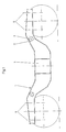
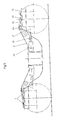
- the embodiment of the drive according to FIGS. 1-4 has a bogie 1, which has two side cheeks 2 lying in the direction of travel, which are connected in the longitudinal center by a main support 3 and on both sides thereof by a brake support 4.
- the dash-dotted lines in FIG. 2 indicate wheelset axles 5, which are mounted at both ends in a wheel set bearing, which is seated in a wheel set bearing housing, which has a wheel set guide pin 6 (FIG. 3) on both sides of the axle, which is supported in FIGS 1 and 5 is indicated by vertical, dash-dotted lines.
- a part of the wheelset bearing housing is designated 7 in FIG. 3.
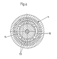
- a guide pot 9 which is lined cylindrically with a sliding bush 10, into which an annular bush 11 is inserted, which has an outer ring 12 and an inner ring 13 and in between a vulcanized, annular, rubber-elastic element 14 , which has diametrically opposed ring segment-shaped recesses 15, 16 on the inside, as seen in the direction of travel.
- the rubber-elastic element 14 has a trapezoidal cross section with inclined walls 17, 19 on the inside.
- extensions 21 and 22 are in the recesses 15 and 16 of the outer bushings of a slide 23 insertable, the bottom 24 of which is provided with a central bore 25 for the passage of a piston rod 26 which is guided in the wheel set guide pin 6 and connected at its upper end to a piston 27.
- the piston 27 is guided in a cylinder 28 fastened in the frame of the running gear or its longitudinal cheeks 2, the cylinder 29 with its walls 29 by a press fit Wheelset guide pin 6 is seated.
- the piston 27 is under the influence of a spring 30 pushing it upwards, which is designed as a helical spring, is supported on the one hand on a shoulder 31 of a cylindrical opening of the wheel set guide pin 6 and on the other hand on the piston 27 and has a tendency to move this piston upwards to press.
- a spring 30 pushing it upwards, which is designed as a helical spring, is supported on the one hand on a shoulder 31 of a cylindrical opening of the wheel set guide pin 6 and on the other hand on the piston 27 and has a tendency to move this piston upwards to press.
- Above the piston 27 there is a space 34 which is closed off by a cylinder cover 33 and which is fed with compressed air via a line 35. Compressed air is supplied to the room 34 from a compressed air tank (not shown) via lines 55-58.
- a hydraulic system can also be used instead of a pneumatic one.
- a bellows 36 is provided, which is attached at its lower end by a clamping ring 37 to a bush 38 which is inserted into the upper end of the guide pot 9.
- the upper end of the bellows 36 is connected to an open, laterally projecting bottom 39 of a pot 40.
- the pot 40 is clamped with its protruding edge of the bottom 39 between a helical spring 41 and a rubber ring 54 of the bogie frame or the side cheek 2 of the same.
- the helical spring 41 serves to fully accommodate the vertical executives and is seated at its lower end on a collar 42 protruding from the guide pot 9, with which the guide pot 9 is supported on the wheel set bearing housing 7 via an insert 43. At the upper end, the spring 41 is supported on the protruding part of the bottom 39 of the pot 40.
- the piston rod 26 is connected to the bottom 24 of the slide 23 by a bolt 44.
- the bushing 11 should be stiff for high speeds, but soft for lower speeds, such as occur, for example, when cornering in arches with small radii.
- the bushing 11 is softly set by the extensions 21, 22 of the slider stepping down from the area of the rubber-elastic element 14. This position of the slide 23 is brought about by admitting compressed air into the space 34, as a result of which the piston 27 with its piston rod 26 also reaches the lowest position against the pressure of the spring 30.
- an increasing rigidity of the bushing 11 is required.
- the inner bushings 100 of a wheelset guide unit can always be made soft and without a slide 23.
- the outer bush will always have the hard setting under the influence of the spring 30, i.e. in this case, the slider 23 will assume the dot-dash position, which is necessary for the stable running of the rail vehicle at high speeds.
- the wheel set guide pin 6 carries two bushes 11A and 11B, which replace the bushing 11.
- the wheelset guide pin 6 is fixedly connected at its upper end to the bogie frame or the side cheek 2.
- the bushing 11A is fixedly connected to the wheel set guide pin 6, while the bushing 11B lying underneath is rotatably mounted about the latter.
- a rotary shaft 26A is provided, which carries at its lower end a driver 61 which engages with claws 62 in the claws 63 of the rotatable bush 11B.
- the rotary shaft 26 A carries at its upper end a lever 64 which is connected to a link 65.
- a link 66 is articulated on the link 65 and is articulated to one end of a double-armed pivot lever 67, the other end of which is articulated to a piston rod 68 of a hydraulic or pneumatic cylinder 69.
- the upper fixed socket 11A can be of any design. For example, it can have a full rubber element between two concentric rings.
- the rotatable bushing 11B like the bushing 11, has a vulcanized-in rubber element 14 between an outer ring 12 and an inner ring 13, which is provided with cutouts 15, 16.
- the rigidity of the upper fixed bushing 11A increased by the rigidity of the lower rotatable bushing 11B when its recesses 15, 16 are located centrally in the vehicle direction X, as shown in FIG. 8, corresponds to a soft setting, ie a setting for driving speeds that are below a critical vehicle speed at which a soft adjustment of the bushing is desired.
- the control mechanism rotates the rotatable bushing up to 90 ° into the position shown in FIG. 9 via the rotary shaft 26A and the driver 61 and the two claw sets 62 and 63, in which the sum of the stiffnesses of the fixed and the rotatable bushing 11A or 11B corresponds to the stiffness which the bushing 11 of the previous exemplary embodiment had in the position of the slider 23 shown in broken lines.
- the rotatable bushing 11B can be controlled by a speed controller which controls the pressure on the piston of the hydraulic or pneumatic cylinder 69.
- the stiffness and damping are Properties formed depending on the direction by the bushing 11B, depending on requirements, is rotated into the corresponding position by the described device, so that the desired stiffness and damping properties in the longitudinal direction (direction of travel) between the wheel sets and the bogie frame come into effect.
Landscapes
- Engineering & Computer Science (AREA)
- Mechanical Engineering (AREA)
- Platform Screen Doors And Railroad Systems (AREA)
- Springs (AREA)
- Support Of The Bearing (AREA)
Applications Claiming Priority (2)
| Application Number | Priority Date | Filing Date | Title |
|---|---|---|---|
| AT234888A AT394981B (de) | 1988-09-23 | 1988-09-23 | Laufwerk fuer schienenfahrzeuge |
| AT2348/88 | 1988-09-23 |
Publications (3)
| Publication Number | Publication Date |
|---|---|
| EP0360782A2 true EP0360782A2 (fr) | 1990-03-28 |
| EP0360782A3 EP0360782A3 (en) | 1990-07-18 |
| EP0360782B1 EP0360782B1 (fr) | 1993-01-27 |
Family
ID=3532672
Family Applications (1)
| Application Number | Title | Priority Date | Filing Date |
|---|---|---|---|
| EP19890890227 Expired - Lifetime EP0360782B1 (fr) | 1988-09-23 | 1989-09-01 | Train de roues pour véhicule ferroviaire |
Country Status (4)
| Country | Link |
|---|---|
| EP (1) | EP0360782B1 (fr) |
| AT (1) | AT394981B (fr) |
| DE (1) | DE58903395D1 (fr) |
| ES (1) | ES2039950T3 (fr) |
Cited By (8)
| Publication number | Priority date | Publication date | Assignee | Title |
|---|---|---|---|---|
| EP0614793A1 (fr) * | 1993-03-09 | 1994-09-14 | Herbert Scheffel | Suspensions pour véhicules ferroviaires |
| EP0624504A1 (fr) * | 1993-05-10 | 1994-11-17 | AEG Schienenfahrzeuge GmbH | Guidage du train de roues pour bogie |
| EP0624505A1 (fr) * | 1993-05-10 | 1994-11-17 | AEG Schienenfahrzeuge GmbH | Guidage du train de roues pour bogie |
| DE4400615C1 (de) * | 1994-01-12 | 1995-03-02 | Talbot Waggonfab | Radsatzführung mit virtueller Radsatz-Schwenkachse |
| US5746134A (en) * | 1993-03-09 | 1998-05-05 | Scheffel; Herbert | Railway vehicle suspensions |
| CN102407861A (zh) * | 2011-10-14 | 2012-04-11 | 同济大学 | 机械式半主动铁道车辆转向架径向导向装置 |
| CN102963384A (zh) * | 2012-07-13 | 2013-03-13 | 南车南京浦镇车辆有限公司 | 铁道车辆刚度可控式轴箱定位装置 |
| WO2018049721A1 (fr) * | 2016-09-19 | 2018-03-22 | 中车大连机车车辆有限公司 | Structure de poutre d'extrémité munie d'un joint en caoutchouc intégré destinée à un bogie |
Family Cites Families (7)
| Publication number | Priority date | Publication date | Assignee | Title |
|---|---|---|---|---|
| BE648895A (fr) * | 1963-05-22 | |||
| CA1221272A (fr) * | 1983-08-12 | 1987-05-05 | James M. Herring, Jr. | Suspension primaire pour voiture ferroviaire |
| IT8423581V0 (it) * | 1984-10-22 | 1984-10-22 | Socimi | Dispositivo di guida antiusura per sospensioni primarie di carrelli ferroviari. |
| DE3528506A1 (de) * | 1985-08-08 | 1987-02-19 | Boge Gmbh | Hydraulischer schwingungsdaempfer zum hemmen eines drehgestells fuer ein schnell lauffaehiges schienenfahrzeug |
| JPS62101575A (ja) * | 1985-10-28 | 1987-05-12 | 川崎重工業株式会社 | 鉄道用台車 |
| DE3706180A1 (de) * | 1987-02-26 | 1988-09-08 | Messerschmitt Boelkow Blohm | Fahrwerk fuer ein schienenfahrzeug |
| DD259383A1 (de) * | 1987-03-31 | 1988-08-24 | Schienenfahrzeugbau Veb K | Schaltung zur regelung von fahrzeugaufhaengungen |
-
1988
- 1988-09-23 AT AT234888A patent/AT394981B/de not_active IP Right Cessation
-
1989
- 1989-09-01 DE DE8989890227T patent/DE58903395D1/de not_active Expired - Lifetime
- 1989-09-01 ES ES89890227T patent/ES2039950T3/es not_active Expired - Lifetime
- 1989-09-01 EP EP19890890227 patent/EP0360782B1/fr not_active Expired - Lifetime
Cited By (11)
| Publication number | Priority date | Publication date | Assignee | Title |
|---|---|---|---|---|
| EP0614793A1 (fr) * | 1993-03-09 | 1994-09-14 | Herbert Scheffel | Suspensions pour véhicules ferroviaires |
| US5588367A (en) * | 1993-03-09 | 1996-12-31 | Scheffel; Herbert | Railway vehicle suspensions |
| US5746134A (en) * | 1993-03-09 | 1998-05-05 | Scheffel; Herbert | Railway vehicle suspensions |
| EP0624504A1 (fr) * | 1993-05-10 | 1994-11-17 | AEG Schienenfahrzeuge GmbH | Guidage du train de roues pour bogie |
| EP0624505A1 (fr) * | 1993-05-10 | 1994-11-17 | AEG Schienenfahrzeuge GmbH | Guidage du train de roues pour bogie |
| DE4400615C1 (de) * | 1994-01-12 | 1995-03-02 | Talbot Waggonfab | Radsatzführung mit virtueller Radsatz-Schwenkachse |
| EP0663330A1 (fr) * | 1994-01-12 | 1995-07-19 | Waggonfabrik Talbot | Guidage du train de roues avec un axe de rotation du train de roues virtuel |
| CN102407861A (zh) * | 2011-10-14 | 2012-04-11 | 同济大学 | 机械式半主动铁道车辆转向架径向导向装置 |
| CN102963384A (zh) * | 2012-07-13 | 2013-03-13 | 南车南京浦镇车辆有限公司 | 铁道车辆刚度可控式轴箱定位装置 |
| CN102963384B (zh) * | 2012-07-13 | 2015-09-09 | 南车南京浦镇车辆有限公司 | 铁道车辆刚度可控式轴箱定位装置 |
| WO2018049721A1 (fr) * | 2016-09-19 | 2018-03-22 | 中车大连机车车辆有限公司 | Structure de poutre d'extrémité munie d'un joint en caoutchouc intégré destinée à un bogie |
Also Published As
| Publication number | Publication date |
|---|---|
| EP0360782B1 (fr) | 1993-01-27 |
| ES2039950T3 (es) | 1993-10-01 |
| ATA234888A (de) | 1992-01-15 |
| DE58903395D1 (de) | 1993-03-11 |
| AT394981B (de) | 1992-08-10 |
| EP0360782A3 (en) | 1990-07-18 |
Similar Documents
| Publication | Publication Date | Title |
|---|---|---|
| DE69612616T2 (de) | Elastische kettenspannvorrichtung für gleiskettenfahrzeuge | |
| DE2624719B2 (de) | Vorrichtung zum Steuern eines lenkbaren Radsatzes an einem Schienenfahrzeug | |
| DE2553494B2 (de) | Einzelradaufhängung für eine Hinterachse von Kraftfahrzeugen, insbesondere von Personenkraftwagen | |
| EP0331889A2 (fr) | Direction sur les quatre roues pour véhicules | |
| DE3723833C2 (de) | Radsatzführung für schnellfahrfähige Drehgestelle von Schienenfahrzeugen und Verfahren zum Umrüsten von Drehgestellen auf diese Radsatzführung | |
| DE2636864A1 (de) | Schienenfahrzeug | |
| DE2301686A1 (de) | Vorrichtung zum ausgleichen der achsdruecke an einem fahrgestell eines fahrzeuges | |
| DE3004082C2 (de) | Einrichtung zur Steuerung der Schwenkbewegung eines Radsatzes eines Schienenfahrzeuges in einer Kurve | |
| EP0360782B1 (fr) | Train de roues pour véhicule ferroviaire | |
| DE102014201621B4 (de) | Verbundlenkerachse für Fahrzeuge | |
| DE2419989B2 (de) | In axialer Richtung bewegliche Achsanordnung | |
| WO2007038917A1 (fr) | Element de guidage pour un element de glissiere de guidage dans une suspension d'un vehicule | |
| EP0360783B1 (fr) | Train de roulement pour véhicules ferroviaires | |
| DE2320323C3 (de) | Radsatzführung, insbesondere für ein Schienenfahrzeug, für Schnellverkehr | |
| EP0156143B1 (fr) | Disposition de montage de dispositifs de frein à sabot pour véhicules sur rails | |
| DE10351574A1 (de) | Verfahren zur Veränderung des Eigenlenkverhaltens der Hinterräder eines zweispurigen Kraftfahrzeugs | |
| EP0689980A1 (fr) | Dispositif de connexion entre de caisses de véhicule adjacents d'un train ferroviaire articulé, notamment entre de véhicules d'un train à plate forme surbaissée | |
| EP3300986A1 (fr) | Dispositif de commande du ressort pneumatique pour un véhicule ferroviaire | |
| AT391113B (de) | Laufwerk fuer schienenfahrzeuge | |
| EP0794101B1 (fr) | Véhicule ferroviaire avec quatre ou six jeux de roues orientables en position radiale | |
| EP0930210A1 (fr) | Train de roulement pour véhicules ferroviaires et véhicule ferroviaire avec au moins un tel train de roulement | |
| AT395138B (de) | Laufwerk fuer schienenfahrzeuge | |
| DE10116882A1 (de) | Verfahren zur Steuerung des Neigungswinkels eines Wagenkastens gegenüber einem Fahrwerk eines Fahrzeugs und Fahrzeug zur Ausübung des Verfahrens | |
| AT280342B (de) | Zweiachsiges Drehgestell für Schienenfahrzeuge | |
| DE19826449C2 (de) | Vorrichtung zur Achsausrichtung von spurgeführten Fahrzeugen |
Legal Events
| Date | Code | Title | Description |
|---|---|---|---|
| PUAI | Public reference made under article 153(3) epc to a published international application that has entered the european phase |
Free format text: ORIGINAL CODE: 0009012 |
|
| AK | Designated contracting states |
Kind code of ref document: A2 Designated state(s): BE CH DE ES FR GB IT LI SE |
|
| PUAL | Search report despatched |
Free format text: ORIGINAL CODE: 0009013 |
|
| AK | Designated contracting states |
Kind code of ref document: A3 Designated state(s): BE CH DE ES FR GB IT LI SE |
|
| RAP1 | Party data changed (applicant data changed or rights of an application transferred) |
Owner name: SGP VERKEHRSTECHNIK GESELLSCHAFT M.B.H. |
|
| 17P | Request for examination filed |
Effective date: 19901011 |
|
| 17Q | First examination report despatched |
Effective date: 19920110 |
|
| GRAA | (expected) grant |
Free format text: ORIGINAL CODE: 0009210 |
|
| AK | Designated contracting states |
Kind code of ref document: B1 Designated state(s): BE CH DE ES FR GB IT LI SE |
|
| ITF | It: translation for a ep patent filed | ||
| REF | Corresponds to: |
Ref document number: 58903395 Country of ref document: DE Date of ref document: 19930311 |
|
| GBT | Gb: translation of ep patent filed (gb section 77(6)(a)/1977) |
Effective date: 19930215 |
|
| ET | Fr: translation filed | ||
| REG | Reference to a national code |
Ref country code: ES Ref legal event code: FG2A Ref document number: 2039950 Country of ref document: ES Kind code of ref document: T3 |
|
| PLBE | No opposition filed within time limit |
Free format text: ORIGINAL CODE: 0009261 |
|
| STAA | Information on the status of an ep patent application or granted ep patent |
Free format text: STATUS: NO OPPOSITION FILED WITHIN TIME LIMIT |
|
| 26N | No opposition filed | ||
| EAL | Se: european patent in force in sweden |
Ref document number: 89890227.5 |
|
| REG | Reference to a national code |
Ref country code: CH Ref legal event code: NV Representative=s name: SIEMENS SCHWEIZ AG Ref country code: CH Ref legal event code: PFA Free format text: SGP VERKEHRSTECHNIK GESELLSCHAFT M.B.H. TRANSFER- SIEMENS SGP VERKEHRSTECHNIK GMBH |
|
| REG | Reference to a national code |
Ref country code: GB Ref legal event code: IF02 |
|
| PGFP | Annual fee paid to national office [announced via postgrant information from national office to epo] |
Ref country code: IT Payment date: 20080924 Year of fee payment: 20 Ref country code: FR Payment date: 20080918 Year of fee payment: 20 |
|
| PGFP | Annual fee paid to national office [announced via postgrant information from national office to epo] |
Ref country code: GB Payment date: 20080911 Year of fee payment: 20 |
|
| PGFP | Annual fee paid to national office [announced via postgrant information from national office to epo] |
Ref country code: CH Payment date: 20081211 Year of fee payment: 20 Ref country code: DE Payment date: 20081121 Year of fee payment: 20 |
|
| PGFP | Annual fee paid to national office [announced via postgrant information from national office to epo] |
Ref country code: ES Payment date: 20081020 Year of fee payment: 20 Ref country code: BE Payment date: 20080915 Year of fee payment: 20 Ref country code: SE Payment date: 20080909 Year of fee payment: 20 |
|
| REG | Reference to a national code |
Ref country code: CH Ref legal event code: PCAR Free format text: SIEMENS SCHWEIZ AG;INTELLECTUAL PROPERTY FREILAGERSTRASSE 40;8047 ZUERICH (CH) |
|
| REG | Reference to a national code |
Ref country code: CH Ref legal event code: PL |
|
| REG | Reference to a national code |
Ref country code: GB Ref legal event code: PE20 Expiry date: 20090831 |
|
| BE20 | Be: patent expired |
Owner name: *SIEMENS SGP VERKEHRSTECHNIK G.M.B.H. Effective date: 20090901 |
|
| EUG | Se: european patent has lapsed | ||
| REG | Reference to a national code |
Ref country code: ES Ref legal event code: FD2A Effective date: 20090902 |
|
| PG25 | Lapsed in a contracting state [announced via postgrant information from national office to epo] |
Ref country code: GB Free format text: LAPSE BECAUSE OF EXPIRATION OF PROTECTION Effective date: 20090831 |
|
| PG25 | Lapsed in a contracting state [announced via postgrant information from national office to epo] |
Ref country code: ES Free format text: LAPSE BECAUSE OF EXPIRATION OF PROTECTION Effective date: 20090902 |