EP0360898B1 - Méthode pour prendre des appels qui sont signalés par un central de communication à un ou plusieurs terminaux de communication à lignes multiples - Google Patents
Méthode pour prendre des appels qui sont signalés par un central de communication à un ou plusieurs terminaux de communication à lignes multiples Download PDFInfo
- Publication number
- EP0360898B1 EP0360898B1 EP88116009A EP88116009A EP0360898B1 EP 0360898 B1 EP0360898 B1 EP 0360898B1 EP 88116009 A EP88116009 A EP 88116009A EP 88116009 A EP88116009 A EP 88116009A EP 0360898 B1 EP0360898 B1 EP 0360898B1
- Authority
- EP
- European Patent Office
- Prior art keywords
- key
- communication
- communication system
- communication terminal
- incoming call
- Prior art date
- Legal status (The legal status is an assumption and is not a legal conclusion. Google has not performed a legal analysis and makes no representation as to the accuracy of the status listed.)
- Expired - Lifetime
Links
Images
Classifications
-
- H—ELECTRICITY
- H04—ELECTRIC COMMUNICATION TECHNIQUE
- H04Q—SELECTING
- H04Q3/00—Selecting arrangements
- H04Q3/42—Circuit arrangements for indirect selecting controlled by common circuits, e.g. register controller, marker
- H04Q3/54—Circuit arrangements for indirect selecting controlled by common circuits, e.g. register controller, marker in which the logic circuitry controlling the exchange is centralised
- H04Q3/545—Circuit arrangements for indirect selecting controlled by common circuits, e.g. register controller, marker in which the logic circuitry controlling the exchange is centralised using a stored program
- H04Q3/54508—Configuration, initialisation
- H04Q3/54533—Configuration data, translation, passwords, databases
-
- H—ELECTRICITY
- H04—ELECTRIC COMMUNICATION TECHNIQUE
- H04M—TELEPHONIC COMMUNICATION
- H04M3/00—Automatic or semi-automatic exchanges
- H04M3/42—Systems providing special services or facilities to subscribers
-
- H—ELECTRICITY
- H04—ELECTRIC COMMUNICATION TECHNIQUE
- H04M—TELEPHONIC COMMUNICATION
- H04M9/00—Arrangements for interconnection not involving centralised switching
- H04M9/002—Arrangements for interconnection not involving centralised switching with subscriber controlled access to a line, i.e. key telephone systems
- H04M9/005—Arrangements for interconnection not involving centralised switching with subscriber controlled access to a line, i.e. key telephone systems with subscriber controlled access to an exchange line
Definitions
- a telephone system In private telephone networks, in addition to individual telephones, a telephone system is also connected to a private branch exchange. These telephone line systems, which are preferably used in office areas, are predominantly connected to the telephone private branch exchange via two or more individual telephone lines.
- the first of the telephone sets connected in series is usually determined as the main station used in the sense of a switching center and the other telephone sets as extensions.
- Each of the in-line telephone sets has line keys, with the aid of which one of the connecting lines leading to the private branch exchange is assigned or a connection arriving on the respective connecting line is accepted. An incoming connection is first displayed acoustically or optically in the main station of the row system.
- row system networks can be created be configured in which the function of a main unit is dispensed with and all telephone sets or communication terminals assigned to a series system are connected to the private branch exchange or communication system with equal rights. This means that all switching procedures initiated by the line keys in the communication terminals must be implemented in the communication system.
- These functions representing the line key functions for row systems are also referred to in the professional world as key performance features of a communication system.
- a connection arriving at a row system is usually initially indicated acoustically or optically in the main station.
- a table containing at least one destination and source address information is created in the communication system for each incoming connection.
- the call terminal information determined by the destination address information _ main station of row systems _ is transmitted and displayed there. If thereupon the lifting of the handset or the actuation of a line key is signaled to the communication system in the respective communication terminal, the incoming connection is connected to the respective communication terminal by a connection establishment procedure implemented in the communication system. If an incoming connection is not accepted in the main station, the incoming connection is displayed on a further communication terminal or all communication terminals assigned to a series system after a predetermined period of time. On these communication terminals, the incoming connection can be accepted by pressing a line key.
- function keys in the communication terminals. These are used primarily to initialize features such as callback, call forwarding, call pickup, etc. In centrally controlled, digital communication systems, these features are implemented partly by existing, partly by added switching technology procedures _ by appropriate programs _.
- the object on which the invention is based is to provide a method for using a key communication terminal signaling on a key function (row system functions), incoming connections, to another key communication terminal belonging to the same group and assigned to the respective row system, with a program that is as small as possible - And to integrate memory in a program-controlled communication system with the properties explained above.
- the object is achieved on the basis of the features of a communication system according to the preamble by the characterizing features of claim 1.
- the core idea of the invention is to be seen in the introduction of group number information, which is the same for the group of key communication terminals assigned to a series system, and in the shared use of the tables created for the incoming connections.
- group number information which is the same for the group of key communication terminals assigned to a series system
- table system functions d. H. Key performance features, minimized in a communication system.
- the main advantage of the invention can be seen in the fact that this easy-to-implement method enables a fast and free assignment of the respective key communication terminal to one or more groups of key communication terminals assigned to each row system. By changing, adding or deleting group number information, the respective key communication terminal can be assigned to any groups of key communication terminals.
- Another advantage of the invention is that this method is not only limited to an application for groups of key communication terminals forming series systems, but can also be used for other groups, such as "closed user groups" etc.
- the incoming connection optically displayed in the specified, line-occupying function key _ see claim 2.
- This optical display _ z. B. realized by a luminescent diode - indicates an incoming connection on the function key that is to be pressed to use incoming connections.
- a key communication terminal can belong not only to one but to several groups of key communication terminals having key functions. In order to indicate to the key communication terminal subscriber which connection arrives for which group, it is particularly advantageous to arrange a separate line-occupying function key for each group in the key communication terminal _ see claim 3.
- an incoming connection is optically and / or acoustically displayed to the remaining communication terminals after a time delay.
- This variant is advantageous if an incoming connection is intended by the specified destination address information for a communication terminal that is assigned to a group of key communication terminals, and this key communication terminal may preferentially accept the incoming connection within a predetermined period of time. After this time has elapsed, the incoming connection is displayed on the remaining key communication terminals assigned to the group.
- a double function can be assigned to a line-occupying function key.
- it is used in the case of a free connecting line in the sense of a line assignment or connection establishment, and on the other hand it is used to use incoming connections as already explained.
- the main advantage of the training according to claim 5 is to be seen in the unchanged reuse of the existing switching procedures (programs), as by the in the additional storage areas specified switching information available in the respective communication system switching procedures _ such.
- B. Occupying a connecting line and sending dialing signals _ can be controlled.
- the assignment of the key performance features to the function keys can be changed by simply changing the information in the additional memory area.
- a change in the change in the information content in the additional memory area of the database of the communication system is usually brought about by an operational input on the operating device assigned to a communication system and by database access procedures implemented in the communications system can be brought about on the key communication terminal _ see claim 7.
- the probability of a malfunction of the switching procedures introduced into the communication system due to improper input be reduced.
- a change in the information content by the communication terminal subscriber offers the latter the possibility of freely assigning the key features to the line-related function keys in the communication terminal.
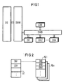
- the basic control structure of a digital communication system shown in FIG. 1 has two control structure levels, one of which is used to control peripheral devices, by means of line technology program modules DH1, DH2 the peripherals of the connected communication terminals, but also central circuit technology devices, such as connection sets and switching matrix, count.
- Each of these line technology program modules DH1, DH2 ... DHn offers a system-uniform interface to the switching technology structure level, which in the present case is represented by a switching procedure program module LDU (Logical Device Unit).
- LDU Logical Device Unit
- the exchange of information between the line technology structure level and the switching technology structure level takes place by means of generally defined messages which are transmitted via a software bus structure SWB, which can be regarded as an integral part of the operating system of a communication computer, not shown.
- the switching procedure program module LDU, the line technology program modules DH1, DH2 ... DHn and the software bus SWB have access to the database DB of the entire communication system by means of database access routines DBAR.
- the line technology program modules DH1, DH2 ... DHn are designed specifically for communication terminal types in such a way that they respectively control the signaling method and the user interface of the corresponding communication terminal type, while the switching procedure program module LDU is structured independently of communication types and communication services in such a way that it provides the maximum functional scope of the peripheral devices and facilities mastered control technology.
- the tasks of the switching procedure program module LDU thus include the subprocesses of the entire switching procedure necessary for controlling the connection establishment and clearing down. So z. B. permissions checked, electoral checks carried out, there is a signaling of switching states between the communication terminals, and it is Activation and deactivation of switching technology features can be carried out from the various switching technology states.
- This memory area in the database DB can be, for example, a working memory of a switching computer arranged in the communication system.
- This data is not retained beyond a restart of the communication system caused by a switching calculation error.
- connection tables PE The basic structure of the dynamic data is essentially determined by connection tables PE.
- a frame table HT is arranged in front of this connection table PE.
- the dynamic data stored in the frame table HT are used to quickly assign group number information formed by a function key to the respective connection tables PE and to control the query priorities.
- information INV, EXV is entered in partial areas of the frame table HT, by means of which this incoming connection is determined, for example, as an external or internal incoming connection.
- Further entries in this frame table for a further differentiation of incoming connections are, for example, _ not shown in FIG. 2 _ data for performance features, such as callback, call forwarding, etc.
- Each of these subareas of the frame table HT is assigned to a respective group associated connection table PE.
- Each incoming connection is assigned a connection table PE, into which in each case destination address data ZAD _, ie the address information of the communication terminal to which the incoming connection is addressed, in sub-areas with the aid of the database access procedures _ and the source address information UAD _ ie the address information of the communication terminal that initiated the incoming connection is to be transmitted.
- the group number data GND determined in the line technology program module DH1, DH2 ... DHn are entered.
- _ not shown _ address information for features such as call diversion, consultation, etc., can be entered.
- the group number data GND _ assigned to the respective communication terminal can also be for several groups with the aid of a line technology program module DH1, DH2 ... DHn _ determined and compared with the group number data GND of the incoming connection. If the group number data GND matches, the incoming connection is connected to the respective communication terminal using the relevant line technology program modules DH1, DH2 ... DHn and the switching technology program module LDU.
Landscapes
- Engineering & Computer Science (AREA)
- Signal Processing (AREA)
- Databases & Information Systems (AREA)
- Computer Networks & Wireless Communication (AREA)
- Sub-Exchange Stations And Push- Button Telephones (AREA)
- Telephonic Communication Services (AREA)
- Mobile Radio Communication Systems (AREA)
- Selective Calling Equipment (AREA)
Claims (7)
Priority Applications (3)
| Application Number | Priority Date | Filing Date | Title |
|---|---|---|---|
| EP88116009A EP0360898B1 (fr) | 1988-09-28 | 1988-09-28 | Méthode pour prendre des appels qui sont signalés par un central de communication à un ou plusieurs terminaux de communication à lignes multiples |
| DE8888116009T DE3862582D1 (de) | 1988-09-28 | 1988-09-28 | Verfahren zum heranziehen von anrufen, die von einer kommunikationsanlage an ein oder mehrere reihenanlagen-kommunikationsendgeraete signalisiert werden. |
| AT88116009T ATE63030T1 (de) | 1988-09-28 | 1988-09-28 | Verfahren zum heranziehen von anrufen, die von einer kommunikationsanlage an ein oder mehrere reihenanlagen-kommunikationsendgeraete signalisiert werden. |
Applications Claiming Priority (1)
| Application Number | Priority Date | Filing Date | Title |
|---|---|---|---|
| EP88116009A EP0360898B1 (fr) | 1988-09-28 | 1988-09-28 | Méthode pour prendre des appels qui sont signalés par un central de communication à un ou plusieurs terminaux de communication à lignes multiples |
Publications (2)
| Publication Number | Publication Date |
|---|---|
| EP0360898A1 EP0360898A1 (fr) | 1990-04-04 |
| EP0360898B1 true EP0360898B1 (fr) | 1991-04-24 |
Family
ID=8199383
Family Applications (1)
| Application Number | Title | Priority Date | Filing Date |
|---|---|---|---|
| EP88116009A Expired - Lifetime EP0360898B1 (fr) | 1988-09-28 | 1988-09-28 | Méthode pour prendre des appels qui sont signalés par un central de communication à un ou plusieurs terminaux de communication à lignes multiples |
Country Status (3)
| Country | Link |
|---|---|
| EP (1) | EP0360898B1 (fr) |
| AT (1) | ATE63030T1 (fr) |
| DE (1) | DE3862582D1 (fr) |
Families Citing this family (1)
| Publication number | Priority date | Publication date | Assignee | Title |
|---|---|---|---|---|
| DE59209259D1 (de) * | 1991-09-30 | 1998-05-07 | Siemens Ag | Verfahren für den Betrieb einer Programmgesteuerten Kommunikationsanlage, bei der eine Verbindungsanforderung gleichzeitig an mehrere Kommunikationsendgeräte signalisiert wird |
Family Cites Families (1)
| Publication number | Priority date | Publication date | Assignee | Title |
|---|---|---|---|---|
| US4150257A (en) * | 1977-10-31 | 1979-04-17 | Bell Telephone Laboratories, Incorporated | Communication system call coverage arrangements |
-
1988
- 1988-09-28 DE DE8888116009T patent/DE3862582D1/de not_active Expired - Lifetime
- 1988-09-28 EP EP88116009A patent/EP0360898B1/fr not_active Expired - Lifetime
- 1988-09-28 AT AT88116009T patent/ATE63030T1/de not_active IP Right Cessation
Also Published As
| Publication number | Publication date |
|---|---|
| EP0360898A1 (fr) | 1990-04-04 |
| DE3862582D1 (de) | 1991-05-29 |
| ATE63030T1 (de) | 1991-05-15 |
Similar Documents
| Publication | Publication Date | Title |
|---|---|---|
| DE4424896C2 (de) | Verfahren zum Errichten und Abrufen eines Telefonbenutzerprofils | |
| EP0306693B1 (fr) | Système de communication numérique à structure modulaire | |
| EP0123890A2 (fr) | Méthode pour l'assignation de données de raccordement pour postes d'abonnés téléphoniques | |
| EP0392141A2 (fr) | Central numérique de télécommunication | |
| EP0106318B1 (fr) | Appareil téléphonique avec indicateurs optiques | |
| EP0295470B1 (fr) | Méthode pour un dispositif de commutation commandé par calculateur, en particulier pour un central téléphonique à touches avec la possibilité de transfert d'appel | |
| DE3818087C2 (fr) | ||
| EP0360898B1 (fr) | Méthode pour prendre des appels qui sont signalés par un central de communication à un ou plusieurs terminaux de communication à lignes multiples | |
| EP0529343B1 (fr) | Méthode d'établir une liaison de communication entre un terminal de communication, connectée à un central de communication, et plusieurs terminaux | |
| EP0535602B1 (fr) | Procédé pour faire fonctionner un système de communication avec commande programmée dans lequel une demande de connexion est signalée simultanément dans plusieurs terminaux de communication | |
| EP0535601A2 (fr) | Procédé pour l'établissement de connexions de conférence dans un système de communication à commande par processeur | |
| DE3832092C2 (fr) | ||
| EP0337163B1 (fr) | Circuit pour commuter d'une opération normale à une opération de secours et inversement dans une installation de commutation téléphonique | |
| EP0649240B1 (fr) | Système de communication | |
| DE4006048C2 (fr) | ||
| EP0309851B1 (fr) | Procédé pour connecter deux terminaux sous l'instigation d'un troisième dans un système de communication numérique | |
| EP0295469B1 (fr) | Méthode pour un dispositif de commutation commandé par calculateur, en particulier pour un dispositif de commutation téléphonique à touches | |
| DE2838223A1 (de) | Verfahren fuer eine konferenzeinrichtung in einer fernmeldeanlage, insbesondere zentral gesteuerten speicherprogrammierten fernsprechnebenstellenanlage | |
| EP0352700B1 (fr) | Méthode pour réaliser une procédure de commande de service spécifique dans un système de communication commandé par calculateur en particulier un système de communication à touches avec la possibilité de branchement sur une connexion existante | |
| DE3435031A1 (de) | Verfahren fuer eine programmgesteuerte fernsprechvermittlungsanlage, insbesondere waehlnebenstellenanlage | |
| EP0339432B1 (fr) | Méthode pour une installation de commutation commandée par calculateur, en particulier pour un central téléphonique à touches dans lequel des terminaux de données et des terminaux téléphoniques sont connectables alternativement | |
| DE3214657A1 (de) | Einrichtung fuer die sprach- und/oder datenvermittlung und -uebertragung | |
| DE3432144A1 (de) | Verfahren fuer eine mit einem betriebstechnischen terminal ausgeruestete waehlnebenstellenanlage | |
| DE19844672B4 (de) | Programmgesteuertes Kommunikationssystem zur Vermittlung von daran angeschlossenen analogen und digitalen Kommunikationsendgeräten | |
| DE19706780A1 (de) | Kommunikationssystem, das die Möglichkeit der Anrufumleitung bietet |
Legal Events
| Date | Code | Title | Description |
|---|---|---|---|
| PUAI | Public reference made under article 153(3) epc to a published international application that has entered the european phase |
Free format text: ORIGINAL CODE: 0009012 |
|
| AK | Designated contracting states |
Kind code of ref document: A1 Designated state(s): AT BE CH DE ES FR GB GR IT LI LU NL SE |
|
| RBV | Designated contracting states (corrected) |
Designated state(s): AT CH DE FR GB LI |
|
| 17P | Request for examination filed |
Effective date: 19900425 |
|
| 17Q | First examination report despatched |
Effective date: 19900803 |
|
| GRAA | (expected) grant |
Free format text: ORIGINAL CODE: 0009210 |
|
| AK | Designated contracting states |
Kind code of ref document: B1 Designated state(s): AT CH DE FR GB LI |
|
| REF | Corresponds to: |
Ref document number: 63030 Country of ref document: AT Date of ref document: 19910515 Kind code of ref document: T |
|
| REF | Corresponds to: |
Ref document number: 3862582 Country of ref document: DE Date of ref document: 19910529 |
|
| ET | Fr: translation filed | ||
| GBT | Gb: translation of ep patent filed (gb section 77(6)(a)/1977) | ||
| PLBE | No opposition filed within time limit |
Free format text: ORIGINAL CODE: 0009261 |
|
| STAA | Information on the status of an ep patent application or granted ep patent |
Free format text: STATUS: NO OPPOSITION FILED WITHIN TIME LIMIT |
|
| 26N | No opposition filed | ||
| PGFP | Annual fee paid to national office [announced via postgrant information from national office to epo] |
Ref country code: CH Payment date: 20001214 Year of fee payment: 13 |
|
| PGFP | Annual fee paid to national office [announced via postgrant information from national office to epo] |
Ref country code: AT Payment date: 20010816 Year of fee payment: 14 |
|
| PG25 | Lapsed in a contracting state [announced via postgrant information from national office to epo] |
Ref country code: LI Free format text: LAPSE BECAUSE OF NON-PAYMENT OF DUE FEES Effective date: 20010930 Ref country code: CH Free format text: LAPSE BECAUSE OF NON-PAYMENT OF DUE FEES Effective date: 20010930 |
|
| REG | Reference to a national code |
Ref country code: GB Ref legal event code: IF02 |
|
| REG | Reference to a national code |
Ref country code: CH Ref legal event code: PL |
|
| PG25 | Lapsed in a contracting state [announced via postgrant information from national office to epo] |
Ref country code: AT Free format text: LAPSE BECAUSE OF NON-PAYMENT OF DUE FEES Effective date: 20020928 |
|
| PGFP | Annual fee paid to national office [announced via postgrant information from national office to epo] |
Ref country code: GB Payment date: 20040907 Year of fee payment: 17 |
|
| PGFP | Annual fee paid to national office [announced via postgrant information from national office to epo] |
Ref country code: FR Payment date: 20040921 Year of fee payment: 17 |
|
| PGFP | Annual fee paid to national office [announced via postgrant information from national office to epo] |
Ref country code: DE Payment date: 20041118 Year of fee payment: 17 |
|
| PG25 | Lapsed in a contracting state [announced via postgrant information from national office to epo] |
Ref country code: GB Free format text: LAPSE BECAUSE OF NON-PAYMENT OF DUE FEES Effective date: 20050928 |
|
| PG25 | Lapsed in a contracting state [announced via postgrant information from national office to epo] |
Ref country code: DE Free format text: LAPSE BECAUSE OF NON-PAYMENT OF DUE FEES Effective date: 20060401 |
|
| GBPC | Gb: european patent ceased through non-payment of renewal fee |
Effective date: 20050928 |
|
| PG25 | Lapsed in a contracting state [announced via postgrant information from national office to epo] |
Ref country code: FR Free format text: LAPSE BECAUSE OF NON-PAYMENT OF DUE FEES Effective date: 20060531 |
|
| REG | Reference to a national code |
Ref country code: FR Ref legal event code: ST Effective date: 20060531 |