EP0360902A1 - Dispositif propulsif pour des systèmes de retention dans des véhicules automobiles - Google Patents
Dispositif propulsif pour des systèmes de retention dans des véhicules automobiles Download PDFInfo
- Publication number
- EP0360902A1 EP0360902A1 EP88116072A EP88116072A EP0360902A1 EP 0360902 A1 EP0360902 A1 EP 0360902A1 EP 88116072 A EP88116072 A EP 88116072A EP 88116072 A EP88116072 A EP 88116072A EP 0360902 A1 EP0360902 A1 EP 0360902A1
- Authority
- EP
- European Patent Office
- Prior art keywords
- closure element
- drive device
- gas generator
- relief path
- working chamber
- Prior art date
- Legal status (The legal status is an assumption and is not a legal conclusion. Google has not performed a legal analysis and makes no representation as to the accuracy of the status listed.)
- Granted
Links
- 230000001141 propulsive effect Effects 0.000 title 1
- 239000007789 gas Substances 0.000 claims abstract description 53
- 239000000463 material Substances 0.000 claims abstract description 14
- 239000006023 eutectic alloy Substances 0.000 claims description 6
- 239000004033 plastic Substances 0.000 claims description 4
- 229920003023 plastic Polymers 0.000 claims description 4
- 239000004743 Polypropylene Substances 0.000 claims description 3
- -1 polypropylene Polymers 0.000 claims description 3
- 229920001155 polypropylene Polymers 0.000 claims description 3
- 238000010276 construction Methods 0.000 description 8
- 238000010438 heat treatment Methods 0.000 description 4
- 230000008018 melting Effects 0.000 description 4
- 238000002844 melting Methods 0.000 description 4
- XAGFODPZIPBFFR-UHFFFAOYSA-N aluminium Chemical compound [Al] XAGFODPZIPBFFR-UHFFFAOYSA-N 0.000 description 3
- 229910052782 aluminium Inorganic materials 0.000 description 3
- 230000009172 bursting Effects 0.000 description 3
- 229910045601 alloy Inorganic materials 0.000 description 2
- 239000000956 alloy Substances 0.000 description 2
- 238000004519 manufacturing process Methods 0.000 description 2
- 229910000838 Al alloy Inorganic materials 0.000 description 1
- 230000000694 effects Effects 0.000 description 1
- 230000001771 impaired effect Effects 0.000 description 1
Images
Classifications
-
- B—PERFORMING OPERATIONS; TRANSPORTING
- B60—VEHICLES IN GENERAL
- B60R—VEHICLES, VEHICLE FITTINGS, OR VEHICLE PARTS, NOT OTHERWISE PROVIDED FOR
- B60R22/00—Safety belts or body harnesses in vehicles
- B60R22/34—Belt retractors, e.g. reels
- B60R22/46—Reels with means to tension the belt in an emergency by forced winding up
- B60R22/4619—Transmission of tensioning power by cable, e.g. using a clutch on reel side
-
- B—PERFORMING OPERATIONS; TRANSPORTING
- B60—VEHICLES IN GENERAL
- B60R—VEHICLES, VEHICLE FITTINGS, OR VEHICLE PARTS, NOT OTHERWISE PROVIDED FOR
- B60R22/00—Safety belts or body harnesses in vehicles
- B60R22/34—Belt retractors, e.g. reels
- B60R22/46—Reels with means to tension the belt in an emergency by forced winding up
- B60R22/4628—Reels with means to tension the belt in an emergency by forced winding up characterised by fluid actuators, e.g. pyrotechnic gas generators
- B60R2022/4661—Reels with means to tension the belt in an emergency by forced winding up characterised by fluid actuators, e.g. pyrotechnic gas generators comprising venting means, e.g. for avoiding overpressure in case of fire or for allowing return motion with energy absorption
Definitions
- the invention relates to a drive device for restraint systems in vehicles, with a pyrotechnic gas generator, the gases of which act on a working chamber.
- Such drive devices are required, for example, in seat belt retensioning devices, as are known from DE-OS 31 31 637.
- Pyrotechnic gas generators are particularly suitable as an energy source for drive devices of this type because they are able to deliver the gas quantities required under extremely high pressure within a short period of a few milliseconds.
- the working chamber of the device for example a cylinder in which a piston slides, has to withstand these high pressures.
- the prevailing pursuit of lightweight construction for saving weight and material in motor vehicle construction finds its limit here with the minimum requirements for the mechanical strength of the device.
- the invention has for its object to develop a drive device of the type mentioned in such a way that with a basic construction and dimensioning that is unchanged compared to a design designed for moderate operating temperatures, any risk of bursting or flying parts is excluded even if the device is heated up to the self-ignition temperature of the gas generator.
- a generic drive device in that the working chamber has an outward discharge path, which is closed by a closure element made of a material that at a temperature above the operating temperature range of the gas generator, which is at most equal to the self-ignition temperature of the gas generator , softened at least to such an extent that the closure element when the Gas generator releases the relief path, but at temperatures within the operating temperature range of the gas generator has such a mechanical strength that the relief path remains closed by the closure element when gas is applied.
- This inventive design of the drive device ensures that if the gas generator self-ignites, for example due to a fire in the motor vehicle, the gases generated under particularly high pressure can largely escape via the relief path. Exposure to the working chamber with extremely high gas pressure is therefore avoided.
- the softening temperature of the material from which the closure element is made should be approximately 120 ° C to 130 ° C; in general, between the softening temperature of the material from which the closure element is made and the self-ignition temperature of the gas generator should be approximately the same or slightly larger temperature difference as between the softening temperature and the upper limit of the operating temperature range of the gas generator. In this way it is achieved that, on the one hand, the closure element does not lose strength within the normal operating temperature range, but, on the other hand, when the self-ignition temperature is reached, the softening of the closure element has already progressed to such an extent that a release of the relief channel is guaranteed with high security.
- the closure element is preferably received in a form-fitting manner in a channel forming the relief path.
- a particularly high load-bearing capacity of the closure element results if it has a widened base surface facing the gas application, that is to say is in particular of a truncated cone shape, and its tight fit in the channel is promoted by the wedge effect under the action of the gas application.
- the closure element then forms a stopper which closes an opening leading to the outside of the working chamber. This plug can also be formed by pouring out the opening, which simplifies production.
- the invention can be applied with particular advantage to the linear drive of a seat belt back tensioning device, the working chamber of which is formed by a cylinder in which a piston can be slid by sliding pressure on one of its end faces.
- the cylinder can then be made of aluminum and bolted to the base receiving the gas generator, although such a construction may not be able to cope with the extremely high loads that would occur if the gas generator self-ignited due to excessive heating of the device if there was no relief path .
- the relief path can be formed between the inner wall of the cylinder and the piston, in particular in the form of a ring which surrounds the outer surface of the piston and which is positively connected to the piston.
- the material from which the closure element is formed can be metallic or synthetic. Eutectic alloys are particularly useful, in particular an alloy composed of 55.5% by weight of Bi and 44.5% by weight of Pb. The melting temperature of such a eutectic alloy is 124 ° C.
- Particularly suitable plastics are those which retain high mechanical strength until they soften, which is particularly true for polypropylene whose softening temperature is around 130 ° C. or somewhat higher.
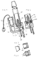
- the drive device for a seat belt rear tensioning device shown in FIG. 1 comprises a generally L-shaped housing 10, in one leg 12 of which a receiving bore for a pyrotechnic gas generator 14 is formed, which bores in a channel 16 up to the other leg 18 bent at right angles continues and merges into a channel 20 formed therein.
- a channel 22 opens into this channel 20, which runs parallel to the channel 16 and merges into the interior of a cylinder 24.
- This interior of the cylinder 24 forms a working chamber in which a piston 26 is slidably received.
- the end of a traction cable 28 is fastened in the piston 26.
- This traction cable 28 engages on the circumference of a cable pulley, which converts the linear movement of the piston 26 into a rotary movement, which is transmitted to the belt reel of a belt retractor in order to tighten the belt.
- the housing 10 is equipped with a mounting flange 30.
- the gas generator 14 has an electrical igniter which is connected to a trigger electronics via a connecting cable 32.
- Both the housing 10 and the cylinder 24 are made of a light material of low strength, in particular aluminum.
- the cylinder 24 is fastened to the housing 10 by means of a threaded connection in that the end of the cylinder 24 which is provided with an external thread is screwed into an extension of the channel 22 which is provided with an internal thread.
- the pyrotechnic gas generator 14 is ignited by means of its electrical igniter by applying a trigger pulse via the cable 32, whereupon gases generated under high pressure act on the end face of the piston 26 via the channels 16, 18, 20 and 22 and in the Working chamber inside the cylinder 24 ben until it is braked in a constriction at the end of the cylinder 24.
- the device In order to avoid any danger from bursting or flying parts in the event of excessive heating of the device, in which the gas generator 14 reaches its self-ignition temperature, the device is equipped with a relief path, which is only released when a temperature is reached which is clearly above the limit of the normal operating temperature range.
- This relief path is formed by an extension of the channel 20.
- This extension of the channel 20 forms an opening in the housing 10, which is closed by a closure element 34.
- the closure element 34 is positively seated in the end of the channel 20.
- the form closure is achieved by an external thread of the closure element 34, which is screwed into a corresponding internal thread at the mouth of the channel.
- the closure element 34 consists of a material which, when heated to temperatures within the operating temperature range of the device, for example up to 80 ° C., has sufficient mechanical strength to withstand the gas pressure during normal operation of the gas generator 14.
- the material from which the closure element 34 is made has a melting or softening point which is below the auto-ignition temperature of the gas generator 14, for example at about 120 to 140 ° C, when the auto-ignition temperature is about 180 ° C.
- a suitable material for the closure element 34 is a eutectic alloy composed of 55.5% by weight of Bi and 44.5% by weight of Pb. This alloy has a melting point of approximately 124 ° C.
- plastics which have a softening point in the range from approximately 120 ° to 150 ° C. are also suitable.
- polypropylene with a melting point of approximately 130 ° to 150 ° C. is suitable.
- the closure element of the relief channel is formed by a ring 38 which surrounds the outer surface of the piston 26 and is positively connected to this by an integrally formed rib 40.
- the ring forming the closure element 38 is thus arranged between the piston 26 and the inner surface of the cylinder 24.
- the closure element 42 forms a frustoconical plug which is inserted into a correspondingly shaped opening 44 in the housing 10 such that its large base area faces the interior of the housing 10.
- closure elements 38 and 42 can be made of the same material as the closure element 34.
- a simple manufacture of the stopper-shaped closure element 34 or 42 is achieved by closing the receiving opening for this closure element by pouring, in particular by means of a eutectic alloy.
Landscapes
- Engineering & Computer Science (AREA)
- Mechanical Engineering (AREA)
- Automotive Seat Belt Assembly (AREA)
- Feeding, Discharge, Calcimining, Fusing, And Gas-Generation Devices (AREA)
- Air Bags (AREA)
Priority Applications (5)
| Application Number | Priority Date | Filing Date | Title |
|---|---|---|---|
| ES88116072T ES2013985T3 (es) | 1988-09-29 | 1988-09-29 | Dispositivo de accionamiento para sistemas de retencion en automoviles. |
| DE8888116072T DE3883388D1 (de) | 1988-09-29 | 1988-09-29 | Antriebsvorrichtung fuer rueckhaltesysteme in kraftfahrzeugen. |
| EP88116072A EP0360902B1 (fr) | 1988-09-29 | 1988-09-29 | Dispositif propulsif pour des systèmes de retention dans des véhicules automobiles |
| US07/366,780 US4927175A (en) | 1988-09-29 | 1989-06-15 | Drive device for restraining systems in motor vehicles |
| JP1193802A JPH0764249B2 (ja) | 1988-09-29 | 1989-07-26 | 自動車の拘束装置のための駆動装置 |
Applications Claiming Priority (1)
| Application Number | Priority Date | Filing Date | Title |
|---|---|---|---|
| EP88116072A EP0360902B1 (fr) | 1988-09-29 | 1988-09-29 | Dispositif propulsif pour des systèmes de retention dans des véhicules automobiles |
Publications (2)
| Publication Number | Publication Date |
|---|---|
| EP0360902A1 true EP0360902A1 (fr) | 1990-04-04 |
| EP0360902B1 EP0360902B1 (fr) | 1993-08-18 |
Family
ID=8199387
Family Applications (1)
| Application Number | Title | Priority Date | Filing Date |
|---|---|---|---|
| EP88116072A Expired - Lifetime EP0360902B1 (fr) | 1988-09-29 | 1988-09-29 | Dispositif propulsif pour des systèmes de retention dans des véhicules automobiles |
Country Status (5)
| Country | Link |
|---|---|
| US (1) | US4927175A (fr) |
| EP (1) | EP0360902B1 (fr) |
| JP (1) | JPH0764249B2 (fr) |
| DE (1) | DE3883388D1 (fr) |
| ES (1) | ES2013985T3 (fr) |
Cited By (6)
| Publication number | Priority date | Publication date | Assignee | Title |
|---|---|---|---|---|
| DE4403980A1 (de) * | 1993-02-10 | 1994-08-11 | Albert Griesemer | Schutzrohr für Gurtstraffer |
| EP0552669B1 (fr) * | 1992-01-20 | 1995-06-21 | TRW Occupant Restraint Systems GmbH | Unité d'entraînement dans un système de retenue pour passagers de véhicule |
| RU2116901C1 (ru) * | 1997-02-12 | 1998-08-10 | Акционерное общество "НОРМА" | Устройство для предварительного натяжения лямки ремня безопасности транспортного средства, устанавливаемое в сидении транспортного средства |
| RU2149780C1 (ru) * | 1998-07-16 | 2000-05-27 | Российский Федеральный Ядерный Центр-Всероссийский Научно-исследовательский Институт Экспериментальной Физики | Устройство для натяжения ремня безопасности |
| FR2796936A1 (fr) | 1999-07-30 | 2001-02-02 | Livbag Snc | Generateur pyrotechnique de gaz a double securite d'ouverture |
| WO2009047186A1 (fr) * | 2007-10-05 | 2009-04-16 | Takata-Petri Ag | Générateur de gaz et procédé pour influencer un écoulement gazeux dans un générateur de gaz |
Families Citing this family (17)
| Publication number | Priority date | Publication date | Assignee | Title |
|---|---|---|---|---|
| JP3115381B2 (ja) * | 1990-11-28 | 2000-12-04 | デイナミート ノーベル アクチエンゲゼルシヤフト | エアバッグ用のガス発生器、特に管型ガス発生器 |
| JPH0624293A (ja) * | 1992-07-08 | 1994-02-01 | Takata Kk | プリテンショナのガス圧作動装置 |
| DE4228696C2 (de) * | 1992-08-28 | 1996-06-20 | Hs Tech & Design | Pyrotechnischer Gasgenerator |
| DE9304152U1 (de) * | 1993-03-20 | 1993-05-13 | TRW Repa GmbH, 7077 Alfdorf | Gurtstraffer mit pyrotechnischem Gasgenerator |
| DE4328760A1 (de) * | 1993-08-26 | 1995-03-02 | Trw Repa Gmbh | Einrichtung zur Befestigung einer allgemein zylindrischen Gasgeneratorpatrone in einer Gurtstraffer-Antriebseinheit |
| DE19645177A1 (de) * | 1996-11-02 | 1998-05-07 | Temic Bayern Chem Airbag Gmbh | Gasgenerator |
| US6017060A (en) * | 1997-11-26 | 2000-01-25 | Trw Vehicle Safety Systems Inc. | Pressure relief plug |
| DE19927270C2 (de) | 1999-06-15 | 2002-07-11 | Breed Automotive Tech | Rückhaltevorrichtung für einen auf eine Gurtspule aufwickelbaren Sicherheitsgurt eines Kraftfahrzeugs |
| JP4651841B2 (ja) | 2001-03-22 | 2011-03-16 | オートリブ株式会社 | シートベルト装置 |
| JP4656556B2 (ja) * | 2001-08-10 | 2011-03-23 | タカタ株式会社 | プリテンショナー |
| DE20312222U1 (de) * | 2003-08-07 | 2003-12-18 | Trw Occupant Restraint Systems Gmbh & Co. Kg | Vorrichtung zum Straffen eines Sicherheitsgurts mit pyrotechnischem Linearantrieb |
| DE102004002428B4 (de) * | 2004-01-16 | 2015-12-17 | Trw Automotive Gmbh | Gurtstraffer für einen Sicherheitsgurtaufroller |
| US20070069518A1 (en) * | 2005-09-27 | 2007-03-29 | Lyons John A | Connector to limit leakage during cleaning of RV sewer lines |
| JP2010095080A (ja) * | 2008-10-15 | 2010-04-30 | Tokai Rika Co Ltd | プリテンショナ |
| DE102009040690A1 (de) * | 2009-09-04 | 2010-04-15 | Takata-Petri Ag | Insassenschutzvorrichtung mit Sicherheitsventil |
| JP5591736B2 (ja) | 2011-02-21 | 2014-09-17 | タカタ株式会社 | プリテンショナー、これを有するシートベルトリトラクタおよびこれを備えたシートベルト装置 |
| DE102020103157B4 (de) * | 2020-02-07 | 2023-06-22 | Autoliv Development Ab | Straffvorrichtung für eine Sicherheitsgurtkomponente |
Citations (2)
| Publication number | Priority date | Publication date | Assignee | Title |
|---|---|---|---|---|
| DE3131637A1 (de) * | 1980-10-06 | 1983-01-27 | Repa Feinstanzwerk Gmbh, 7071 Alfdorf | Rueckstrammer fuer sicherheitsgurtwickelautomaten |
| WO1987001664A1 (fr) * | 1985-09-17 | 1987-03-26 | Allied Engineering Company S.A. | Enrouleur de ceinture pour tendeur dorsal |
Family Cites Families (6)
| Publication number | Priority date | Publication date | Assignee | Title |
|---|---|---|---|---|
| JPS49124731U (fr) * | 1973-02-22 | 1974-10-25 | ||
| US4385775A (en) * | 1978-03-21 | 1983-05-31 | Nippon Soken, Inc. | Seat belt tensioning device for vehicle |
| JPS5825156U (ja) * | 1981-08-12 | 1983-02-17 | トヨタ自動車株式会社 | シ−トベルト引締め装置 |
| DE3238710C2 (de) * | 1982-10-19 | 1986-10-23 | TRW Repa GmbH, 7077 Alfdorf | Antriebsvorrichtung mit in einem Zylinder pyrotechnisch angetriebenem Kolben |
| DE8621257U1 (de) * | 1986-08-08 | 1986-09-25 | TRW Repa GmbH, 7077 Alfdorf | Gasgenerator für Rückstrammer an Sicherheitsgurtaufrollern |
| JPS63212151A (ja) * | 1987-02-26 | 1988-09-05 | Fuji Kiko Co Ltd | 安全ベルトの緊急巻取り装置 |
-
1988
- 1988-09-29 EP EP88116072A patent/EP0360902B1/fr not_active Expired - Lifetime
- 1988-09-29 ES ES88116072T patent/ES2013985T3/es not_active Expired - Lifetime
- 1988-09-29 DE DE8888116072T patent/DE3883388D1/de not_active Expired - Fee Related
-
1989
- 1989-06-15 US US07/366,780 patent/US4927175A/en not_active Expired - Lifetime
- 1989-07-26 JP JP1193802A patent/JPH0764249B2/ja not_active Expired - Fee Related
Patent Citations (2)
| Publication number | Priority date | Publication date | Assignee | Title |
|---|---|---|---|---|
| DE3131637A1 (de) * | 1980-10-06 | 1983-01-27 | Repa Feinstanzwerk Gmbh, 7071 Alfdorf | Rueckstrammer fuer sicherheitsgurtwickelautomaten |
| WO1987001664A1 (fr) * | 1985-09-17 | 1987-03-26 | Allied Engineering Company S.A. | Enrouleur de ceinture pour tendeur dorsal |
Cited By (8)
| Publication number | Priority date | Publication date | Assignee | Title |
|---|---|---|---|---|
| EP0552669B1 (fr) * | 1992-01-20 | 1995-06-21 | TRW Occupant Restraint Systems GmbH | Unité d'entraînement dans un système de retenue pour passagers de véhicule |
| DE4403980A1 (de) * | 1993-02-10 | 1994-08-11 | Albert Griesemer | Schutzrohr für Gurtstraffer |
| DE4403980C2 (de) * | 1993-02-10 | 2000-06-29 | Albert Griesemer | Schutzrohr für Gurtstraffer |
| RU2116901C1 (ru) * | 1997-02-12 | 1998-08-10 | Акционерное общество "НОРМА" | Устройство для предварительного натяжения лямки ремня безопасности транспортного средства, устанавливаемое в сидении транспортного средства |
| RU2149780C1 (ru) * | 1998-07-16 | 2000-05-27 | Российский Федеральный Ядерный Центр-Всероссийский Научно-исследовательский Институт Экспериментальной Физики | Устройство для натяжения ремня безопасности |
| FR2796936A1 (fr) | 1999-07-30 | 2001-02-02 | Livbag Snc | Generateur pyrotechnique de gaz a double securite d'ouverture |
| WO2009047186A1 (fr) * | 2007-10-05 | 2009-04-16 | Takata-Petri Ag | Générateur de gaz et procédé pour influencer un écoulement gazeux dans un générateur de gaz |
| US8028627B2 (en) | 2007-10-05 | 2011-10-04 | Takata-Petri Ag | Gas generator and method for influencing a gas flow in a gas generator |
Also Published As
| Publication number | Publication date |
|---|---|
| JPH0764249B2 (ja) | 1995-07-12 |
| US4927175A (en) | 1990-05-22 |
| DE3883388D1 (de) | 1993-09-23 |
| ES2013985A4 (es) | 1990-06-16 |
| ES2013985T3 (es) | 1994-01-16 |
| JPH02147457A (ja) | 1990-06-06 |
| EP0360902B1 (fr) | 1993-08-18 |
Similar Documents
| Publication | Publication Date | Title |
|---|---|---|
| EP0360902B1 (fr) | Dispositif propulsif pour des systèmes de retention dans des véhicules automobiles | |
| EP0614789B1 (fr) | Prétendeur pour systèmes de ceinture de sécurité pour véhicules | |
| EP0539872B1 (fr) | Générateur de gaz, en particulier pour un coussin gonflable de protection d'un passager de véhicule contre les blessures | |
| DE2253657C2 (de) | Vorrichtung zum Spannen von Sicherheitsgurten in Fahrzeugen | |
| DE60111319T2 (de) | Pyrotechnischer Aktuator | |
| EP0616928B1 (fr) | Tendeur de sangle pour ceintures de sécurité avec moteur pyrotechnique | |
| EP0490252B1 (fr) | Dispositif pour l'allumage d'une charge propulsive; cartouches et magasin pour des cartouches susceptibles d'être allumées adiabatiquement, notamment pour des appareils de clouage par explosion | |
| EP0680857B1 (fr) | Générateur de gaz pour système de retenue dans un véhicule | |
| EP0780272A2 (fr) | Entraînement linéaire pour un tendeur de ceinture de sécurité | |
| EP0808752B1 (fr) | Tendeur de ceinture d'un dispositif de retenue des passagers d'un véhicule | |
| DE2436754A1 (de) | Durch explosiv-treibstoff betaetigte sicherheitsgurt-spannvorrichtung mit mechanischer stossdaempfung | |
| EP0614790B1 (fr) | Prétendeur pour systèmes de ceinture de sécurité dans les véhicules | |
| DE2330635B2 (de) | Durch eine Treibladung betätigte Einstellvorrichtung | |
| DE2505624A1 (de) | Spannvorrichtung fuer einen sicherheitsgurt von fahrzeugen, insbesondere kraftfahrzeugen | |
| DE29710011U1 (de) | Linearantrieb für einen Gurtstraffer | |
| DE19927270A1 (de) | Rückhaltevorrichtung für einen auf eine Gurtspule aufwickelbaren Sicherheitsgurt eines Kraftfahrzeugs | |
| DE2624942A1 (de) | Vorrichtung zum spannen und wiedernachgeben von sicherheitsgurten | |
| EP1498635B1 (fr) | Elément de réglage comportant un cylindre | |
| DE2509496A1 (de) | Druckgaspatrone fuer brandschutzzwecke | |
| EP0876269B1 (fr) | Dispositif d'entrainement pour un systeme de retenue de passagers | |
| DE4208157C2 (de) | Vorrichtung zum Straffen eines Sicherheitsgurtes in einem Kraftfahrzeug | |
| DE29811538U1 (de) | Gurtstraffer | |
| DE102023124606A1 (de) | Pyrotechnisches Trennsystem für insbesondere mechanisch gefügte Verbindungen | |
| DE102022105493A1 (de) | Anzündermodul und gasgenerator | |
| DE3838581A1 (de) | Gepresste hohlladung |
Legal Events
| Date | Code | Title | Description |
|---|---|---|---|
| PUAI | Public reference made under article 153(3) epc to a published international application that has entered the european phase |
Free format text: ORIGINAL CODE: 0009012 |
|
| AK | Designated contracting states |
Kind code of ref document: A1 Designated state(s): DE ES FR GB IT SE |
|
| ITCL | It: translation for ep claims filed |
Representative=s name: DR. ING. A. RACHELI & C. |
|
| EL | Fr: translation of claims filed | ||
| GBC | Gb: translation of claims filed (gb section 78(7)/1977) | ||
| 17P | Request for examination filed |
Effective date: 19900710 |
|
| 17Q | First examination report despatched |
Effective date: 19921218 |
|
| GRAA | (expected) grant |
Free format text: ORIGINAL CODE: 0009210 |
|
| AK | Designated contracting states |
Kind code of ref document: B1 Designated state(s): DE ES FR GB IT SE |
|
| REF | Corresponds to: |
Ref document number: 3883388 Country of ref document: DE Date of ref document: 19930923 |
|
| ET | Fr: translation filed | ||
| ITF | It: translation for a ep patent filed | ||
| GBT | Gb: translation of ep patent filed (gb section 77(6)(a)/1977) |
Effective date: 19931014 |
|
| REG | Reference to a national code |
Ref country code: ES Ref legal event code: FG2A Ref document number: 2013985 Country of ref document: ES Kind code of ref document: T3 |
|
| PLBE | No opposition filed within time limit |
Free format text: ORIGINAL CODE: 0009261 |
|
| STAA | Information on the status of an ep patent application or granted ep patent |
Free format text: STATUS: NO OPPOSITION FILED WITHIN TIME LIMIT |
|
| 26N | No opposition filed | ||
| EAL | Se: european patent in force in sweden |
Ref document number: 88116072.5 |
|
| PGFP | Annual fee paid to national office [announced via postgrant information from national office to epo] |
Ref country code: SE Payment date: 19990901 Year of fee payment: 12 |
|
| PG25 | Lapsed in a contracting state [announced via postgrant information from national office to epo] |
Ref country code: SE Free format text: THE PATENT HAS BEEN ANNULLED BY A DECISION OF A NATIONAL AUTHORITY Effective date: 20000929 |
|
| EUG | Se: european patent has lapsed |
Ref document number: 88116072.5 |
|
| REG | Reference to a national code |
Ref country code: GB Ref legal event code: IF02 |
|
| PGFP | Annual fee paid to national office [announced via postgrant information from national office to epo] |
Ref country code: GB Payment date: 20030807 Year of fee payment: 16 |
|
| PGFP | Annual fee paid to national office [announced via postgrant information from national office to epo] |
Ref country code: FR Payment date: 20040902 Year of fee payment: 17 |
|
| PGFP | Annual fee paid to national office [announced via postgrant information from national office to epo] |
Ref country code: ES Payment date: 20040923 Year of fee payment: 17 |
|
| PG25 | Lapsed in a contracting state [announced via postgrant information from national office to epo] |
Ref country code: GB Free format text: LAPSE BECAUSE OF NON-PAYMENT OF DUE FEES Effective date: 20040929 |
|
| GBPC | Gb: european patent ceased through non-payment of renewal fee |
Effective date: 20040929 |
|
| PG25 | Lapsed in a contracting state [announced via postgrant information from national office to epo] |
Ref country code: IT Free format text: LAPSE BECAUSE OF NON-PAYMENT OF DUE FEES Effective date: 20050929 |
|
| PG25 | Lapsed in a contracting state [announced via postgrant information from national office to epo] |
Ref country code: ES Free format text: LAPSE BECAUSE OF NON-PAYMENT OF DUE FEES Effective date: 20050930 |
|
| PGFP | Annual fee paid to national office [announced via postgrant information from national office to epo] |
Ref country code: DE Payment date: 20050930 Year of fee payment: 18 |
|
| PG25 | Lapsed in a contracting state [announced via postgrant information from national office to epo] |
Ref country code: FR Free format text: LAPSE BECAUSE OF NON-PAYMENT OF DUE FEES Effective date: 20060531 |
|
| REG | Reference to a national code |
Ref country code: FR Ref legal event code: ST Effective date: 20060531 |
|
| REG | Reference to a national code |
Ref country code: ES Ref legal event code: FD2A Effective date: 20050930 |
|
| PG25 | Lapsed in a contracting state [announced via postgrant information from national office to epo] |
Ref country code: DE Free format text: LAPSE BECAUSE OF NON-PAYMENT OF DUE FEES Effective date: 20070403 |