EP0360981A2 - Réacteur pour l'exécution des réactions catalytiques en phase gazeuse comprenant une chemise résistante à la pression et de fond en forme d'une sphère à la partie extérieure de la face de deux côtés - Google Patents
Réacteur pour l'exécution des réactions catalytiques en phase gazeuse comprenant une chemise résistante à la pression et de fond en forme d'une sphère à la partie extérieure de la face de deux côtés Download PDFInfo
- Publication number
- EP0360981A2 EP0360981A2 EP89110439A EP89110439A EP0360981A2 EP 0360981 A2 EP0360981 A2 EP 0360981A2 EP 89110439 A EP89110439 A EP 89110439A EP 89110439 A EP89110439 A EP 89110439A EP 0360981 A2 EP0360981 A2 EP 0360981A2
- Authority
- EP
- European Patent Office
- Prior art keywords
- cold gas
- reactor
- spherical
- catalyst bed
- nozzle
- Prior art date
- Legal status (The legal status is an assumption and is not a legal conclusion. Google has not performed a legal analysis and makes no representation as to the accuracy of the status listed.)
- Granted
Links
Images


Classifications
-
- C—CHEMISTRY; METALLURGY
- C07—ORGANIC CHEMISTRY
- C07C—ACYCLIC OR CARBOCYCLIC COMPOUNDS
- C07C29/00—Preparation of compounds having hydroxy or O-metal groups bound to a carbon atom not belonging to a six-membered aromatic ring
- C07C29/15—Preparation of compounds having hydroxy or O-metal groups bound to a carbon atom not belonging to a six-membered aromatic ring by reduction of oxides of carbon exclusively
- C07C29/151—Preparation of compounds having hydroxy or O-metal groups bound to a carbon atom not belonging to a six-membered aromatic ring by reduction of oxides of carbon exclusively with hydrogen or hydrogen-containing gases
- C07C29/152—Preparation of compounds having hydroxy or O-metal groups bound to a carbon atom not belonging to a six-membered aromatic ring by reduction of oxides of carbon exclusively with hydrogen or hydrogen-containing gases characterised by the reactor used
-
- B—PERFORMING OPERATIONS; TRANSPORTING
- B01—PHYSICAL OR CHEMICAL PROCESSES OR APPARATUS IN GENERAL
- B01J—CHEMICAL OR PHYSICAL PROCESSES, e.g. CATALYSIS OR COLLOID CHEMISTRY; THEIR RELEVANT APPARATUS
- B01J8/00—Chemical or physical processes in general, conducted in the presence of fluids and solid particles; Apparatus for such processes
- B01J8/0005—Catalytic processes under superatmospheric pressure
-
- B—PERFORMING OPERATIONS; TRANSPORTING
- B01—PHYSICAL OR CHEMICAL PROCESSES OR APPARATUS IN GENERAL
- B01J—CHEMICAL OR PHYSICAL PROCESSES, e.g. CATALYSIS OR COLLOID CHEMISTRY; THEIR RELEVANT APPARATUS
- B01J8/00—Chemical or physical processes in general, conducted in the presence of fluids and solid particles; Apparatus for such processes
- B01J8/02—Chemical or physical processes in general, conducted in the presence of fluids and solid particles; Apparatus for such processes with stationary particles, e.g. in fixed beds
- B01J8/0278—Feeding reactive fluids
Definitions
- the invention relates to a reactor for carrying out catalytic gas reactions with a pressure-resistant jacket and a spherical bottom in each case on the front outer edge, a catalyst bed being arranged at least in the area of the jacket, above the height of which a plurality of cold gas feeds opening into the catalyst bed are provided.
- Such a reactor is known from DE-AS 15 42 209, in which cold gas feeds arranged above the height of the cylindrical jacket consist of cages with perforated walls which are arranged transversely to the flow direction of the reaction gas and form perforated walls which preferably have tubes arranged in their interior for the feed line of the cold gas, in order to enable the entry of a substantial proportion of the reaction gas into the cages, these are designed to be correspondingly large.
- the size of these cages requires a relatively large amount of space for the cold gas supply internals, so that the space available for the catalyst and thus the reaction space is unnecessarily limited. Although a relatively satisfactory temperature control can be achieved in the reactor, the performance of the reactor is unsatisfactory due to the limited available reaction space.
- the object of the invention is to provide a solution with which the reaction space filled with a catalyst of such a reactor can be enlarged, with the most uniform possible temperature distribution should also be adjustable in the additional space.
- This object is achieved according to the invention with a reactor of the type mentioned at the outset in that a catalyst bed with cold gas feeds is arranged in the region of the spherical bottoms, the cold gas feeds being in the form of vertically arranged nozzle pipes with essentially horizontal feed lines.
- the additional arrangement of catalyst beds in the region of the spherical trays enables the reaction space to be substantially enlarged, and the formation of cold gas feeds in the region of the spherical trays also enables a very uniform temperature distribution in this region.
- the use of cold gas feeds in the area of the spherical bottoms, which have only a limited interior space, is only possible due to the very space-saving design according to the invention.
- Known cold gas feeds as in DE-AS 15 42 209 cannot be introduced into conventional spherical bottoms due to their large space requirement.
- the formation of nozzle pipes is a very Fine cold gas distribution achieved, which results in a particularly good mixing with the hot reaction gases and thus a uniform temperature distribution.
- the nozzle tubes in the upper spherical plate are directed upwards and the nozzle tubes in the lower spherical plate are arranged on the respective feed lines.
- the space available in the respective spherical floor can be optimally used, i.e. in spite of the limited space available in the area of the spherical bottoms, a sufficient amount of cold gas can be finely distributed to the respective catalyst bed and thus to the hot reaction gas.
- the invention provides, in a structurally particularly simple and space-saving manner, that the feed lines are designed as distributor pipes arranged on both sides of a central pipe with a cold gas supply pipe arranged centrally and penetrating the spherical bottom jacket.
- the cold gas feeds are preferably installed in such a way that the distributor pipes are arranged approximately in the transition region between the cylindrical reactor jacket and the respective spherical floor.
- This compact design is also particularly suitable for retrofitting reactors.
- the nozzle pipes on the outer edge are shorter than the inner nozzle pipes.
- This design which is adapted to the hemispherical wall surface of the respective spherical floor, allows the spherical floor space to be used even better.
- the distributor pipes are arranged next to one another on the central pipe at a distance which enables a catalyst flow.
- the catalyst can then flow freely through the space between the distributor pipes when filling or emptying.
- the invention also provides that the nozzle tubes are surrounded by a perforated casing, which is preferably formed from expanded metal. This coating on the one hand prevents the nozzle openings of the nozzle pipes from being clogged by the catalyst, and on the other hand ensures that the outflowing cold gas can enter the catalyst bed unhindered.
- a reactor is particularly suitable for methanol synthesis at high pressures and temperatures between 200 and 300 ° C.
- this reactor can also be used for other exothermic or endothermic catalytic gas reactions.
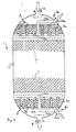
- the reactor 1 is shown in the drawing only with the features essential to the invention.
- the reactor has a cylindrical shell 2, an upper spherical plate 3 with gas inlet socket 4 and a lower spherical plate 5 with gas outlet socket 6.
- a catalyst bed 7 is arranged in the region of the cylindrical jacket 2, a plurality of cold gas feeds opening into the catalyst bed being provided above the height of the catalyst bed 7, which are not shown in the drawing and which are also not important here.
- an additional kata Analyzer bed 7a, 7b provided with cold gas feeds 8a, 8b.
- the additional catalyst beds 7a, 7b are shown in the drawing as single beds, but the catalyst beds can, of course, also be connected directly to the catalyst bed 7, ie, they can be designed as a common catalyst bed which essentially fills the entire reactor 1.
- the cold gas feeds 8a, 8b are formed by vertically arranged nozzle tubes 9a, 9b with essentially horizontal feed lines 10a, 10b.
- the nozzle tubes 9a in the upper spherical base 3 are directed vertically upward and the nozzle tubes 9b in the lower spherical base 5 are directed vertically downward, the outer edge-side nozzle tubes preferably being shorter, i.e. are adapted to the curved wall surface of the spherical floors, so that an optimal use of space is possible.
- the feed lines 10a consist of a central tube 11a with distributor tubes 12a arranged on both sides of the same, on which the nozzle tubes 9a are arranged.
- the central tube 11a is connected in the center to a cold gas supply tube 13a, which penetrates the jacket of the upper spherical base 3 and has a cold gas connecting piece 14a at the free end.
- the feed lines 10b in the region of the lower spherical base 5 are designed accordingly, wherein in Fig. 1 the same reference numerals are used with the addition "b".
- the individual distributor pipes are arranged next to one another in such a way that the clear distance between the individual distributor pipes is sufficiently large to allow a catalyst flow when filling or emptying. It has been found that a clear distance of approximately 80 mm is particularly favorable, which distance naturally also depends on the grain size of the catalyst.
- each nozzle tube 9a has a disk-shaped cover 15a, the outer diameter of which is larger than the outer diameter of the nozzle tube 9a, so that a bearing surface 16a is formed for a perforated casing 17a.
- This casing is preferably made of expanded metal. and envelops the outer region of the nozzle tube 9a in which a plurality of nozzle openings 18a are formed. The sheathing prevents the nozzle openings 18a from clogging and clogging with catalyst.
- the cold gas feeds 8a, 8b are arranged in the reactor 1 in such a way that the feed lines 10a, 10b are located in the transition area from the cylindrical jacket 2 to the spherical bottoms 3, 5.
- the cylindrical region 2 is first filled with the lower spherical base 5 and then the region of the upper spherical base 3, the upper spherical base 3 initially being filled to compensate for later catalyst shrinkage than is shown in the drawing .
- the reaction gases are introduced into the reactor 1 through the gas inlet port 4 and flow essentially vertically from top to bottom, first through the upper catalyst bed 7a, the catalyst bed 7 and finally through the lower catalyst bed 7b in order to leave the reactor through the gas outlet port 6.
- a temperature increase in the catalyst bed 7a, 7, 7b during the reaction is avoided by introducing cold gas, cold gas feeds being provided in a known manner in the cylindrical region 7, of course, cold gas feeds corresponding to the cold gas feeds 8a, 8b can also be used.
- the cold gas is introduced through the cold gas connecting piece 16a and flows through the cold gas supply pipe 13a into the central pipe 11a and from there via the individual distributor pipes 12a into the nozzle pipes 9a.
- the cold gas enters the catalyst bed 7a finely distributed perpendicular to the main flow direction of the hot reaction gas and mixes with the reaction gas so that a uniform temperature distribution in the catalyst bed 7a is established.
- a uniform escape of the cold gas through the nozzle openings 18a is ensured in that the cold gas is introduced into the cold gas supply pipe 13a at a correspondingly high pressure.
- the cold gas supply in the lower ball bottom 5 is carried out analogously.
- an additional catalyst bed 7a can also be provided only in the upper ball floor 3, as well as only in the lower ball floor 5 and the like. More.
Landscapes
- Chemical & Material Sciences (AREA)
- Organic Chemistry (AREA)
- Chemical Kinetics & Catalysis (AREA)
- Devices And Processes Conducted In The Presence Of Fluids And Solid Particles (AREA)
Applications Claiming Priority (2)
| Application Number | Priority Date | Filing Date | Title |
|---|---|---|---|
| DE3829215 | 1988-08-29 | ||
| DE3829215A DE3829215A1 (de) | 1988-08-29 | 1988-08-29 | Reaktor zur durchfuehrung katalytischer gasreaktionen mit einem druckfesten mantel und je einem kugelboden am stirnseitigen aussenrand |
Publications (3)
| Publication Number | Publication Date |
|---|---|
| EP0360981A2 true EP0360981A2 (fr) | 1990-04-04 |
| EP0360981A3 EP0360981A3 (en) | 1990-04-18 |
| EP0360981B1 EP0360981B1 (fr) | 1992-05-20 |
Family
ID=6361785
Family Applications (1)
| Application Number | Title | Priority Date | Filing Date |
|---|---|---|---|
| EP89110439A Expired - Lifetime EP0360981B1 (fr) | 1988-08-29 | 1989-06-09 | Réacteur pour l'exécution des réactions catalytiques en phase gazeuse comprenant une chemise résistante à la pression et de fond en forme d'une sphère à la partie extérieure de la face de deux côtés |
Country Status (3)
| Country | Link |
|---|---|
| EP (1) | EP0360981B1 (fr) |
| DE (2) | DE3829215A1 (fr) |
| ES (1) | ES2031660T3 (fr) |
Cited By (4)
| Publication number | Priority date | Publication date | Assignee | Title |
|---|---|---|---|---|
| US7682579B2 (en) * | 2004-01-21 | 2010-03-23 | Uhde Gmbh | Method and device for nozzle-jetting of oxygen with radial catalyst flow |
| US8043577B2 (en) | 2003-12-19 | 2011-10-25 | Uhde Gmbh | Method and device for nozzle-jetting oxygen into a synthesis reactor |
| FR2974739A1 (fr) * | 2011-05-03 | 2012-11-09 | Commissariat Energie Atomique | Module de reacteur solide / gaz caloporteur comprenant des diffuseurs de gaz a risques d'obturation reduits |
| CN116422118A (zh) * | 2023-04-18 | 2023-07-14 | 中国华电科工集团有限公司 | 一种烟气脱硫氧化风系统及其使用方法 |
Family Cites Families (10)
| Publication number | Priority date | Publication date | Assignee | Title |
|---|---|---|---|---|
| US2961304A (en) * | 1959-03-09 | 1960-11-22 | Shell Oil Co | Apparatus and method for contacting fluids and solids |
| GB1105614A (en) * | 1964-04-22 | 1968-03-06 | Ici Ltd | Catalytic converter |
| US3466152A (en) * | 1965-07-28 | 1969-09-09 | Ube Kogyo Kk | Synthetizing reactor equipped with temperature control device for catalyst layer |
| US3480407A (en) * | 1967-02-02 | 1969-11-25 | Vulcan Cincinnati Inc | Multiple zone apparatus for the processing of fluids having interzone fluid mixing and redistribution features |
| AT289847B (de) * | 1969-03-18 | 1971-05-10 | Chemie Linz Ag | Verfahren und Vorrichtung zur alleinigen oder zusätzlichen Temperaturregelung von Hochdrucksynthesereaktoren, vorzugsweise für die Ammoniaksynthese, durch Kaltgaseinspeisung |
| GB1307845A (en) * | 1969-05-28 | 1973-02-21 | Ici Ltd | Reactor |
| US3663179A (en) * | 1970-04-20 | 1972-05-16 | Chemical Construction Corp | Apparatus for exothermic catalytic reactions |
| US3915847A (en) * | 1974-02-22 | 1975-10-28 | Universal Oil Prod Co | Distribution of liquid-vapor feeds in packed chambers |
| GB2065492B (en) * | 1979-12-21 | 1983-10-19 | Uop Inc | Fluid distributor for fixed-bed catalytic reaction zones |
| DE3318098A1 (de) * | 1983-05-18 | 1984-11-22 | Linde Ag, 6200 Wiesbaden | Verfahren und reaktor zur durchfuehrung einer endo- oder exothermen reaktion |
-
1988
- 1988-08-29 DE DE3829215A patent/DE3829215A1/de not_active Withdrawn
-
1989
- 1989-06-09 EP EP89110439A patent/EP0360981B1/fr not_active Expired - Lifetime
- 1989-06-09 DE DE8989110439T patent/DE58901487D1/de not_active Expired - Fee Related
- 1989-06-09 ES ES198989110439T patent/ES2031660T3/es not_active Expired - Lifetime
Cited By (4)
| Publication number | Priority date | Publication date | Assignee | Title |
|---|---|---|---|---|
| US8043577B2 (en) | 2003-12-19 | 2011-10-25 | Uhde Gmbh | Method and device for nozzle-jetting oxygen into a synthesis reactor |
| US7682579B2 (en) * | 2004-01-21 | 2010-03-23 | Uhde Gmbh | Method and device for nozzle-jetting of oxygen with radial catalyst flow |
| FR2974739A1 (fr) * | 2011-05-03 | 2012-11-09 | Commissariat Energie Atomique | Module de reacteur solide / gaz caloporteur comprenant des diffuseurs de gaz a risques d'obturation reduits |
| CN116422118A (zh) * | 2023-04-18 | 2023-07-14 | 中国华电科工集团有限公司 | 一种烟气脱硫氧化风系统及其使用方法 |
Also Published As
| Publication number | Publication date |
|---|---|
| EP0360981A3 (en) | 1990-04-18 |
| DE58901487D1 (de) | 1992-06-25 |
| DE3829215A1 (de) | 1990-03-08 |
| EP0360981B1 (fr) | 1992-05-20 |
| ES2031660T3 (es) | 1992-12-16 |
Similar Documents
| Publication | Publication Date | Title |
|---|---|---|
| DE3817303C2 (fr) | ||
| DE3943581C2 (fr) | ||
| DE3686783T2 (de) | Verfahren zum herabsetzen des energieverbrauchs von reaktoren fuer die heterogenen katalytischen synthesen. | |
| DE60119211T2 (de) | Mehrzweckige Teilmontage, die Denkontakt, die Verteilung und den Wärme- und/oder Materialaustausch in mindestens einer Gasphase sowie einer Flüssigphase sicherstellt | |
| DE2848086C2 (de) | Röhrenreaktor für katalytische Prozesse | |
| DE60125658T2 (de) | Vorrichtung zur Einspritzung von Fluid zwischen zwei Schichten zur gleichzeitigen Ausführung und Verteilung einer Mehrphasenmischung | |
| DE2512924A1 (de) | Vorrichtung zum verteilen teilchenfoermigen materials | |
| DE19912318A1 (de) | Plattenreaktor | |
| DE69927535T2 (de) | Sprühdüse und Verfahren zu ihrer Verwendung | |
| EP0552457A1 (fr) | Plaque distributrice destinée à un réacteur à lit mobile | |
| DE60225712T2 (de) | Suspensionsverfahren für die kohlenwasserstoffsynthese mit externer hydroisomerierung in einem abstrom-schlaufenreaktor | |
| DE2841127A1 (de) | Sekundaer-reformieranlage fuer ein ammoniak-syntheseverfahren, insbesondere nach dem haber-bosch-prinzip | |
| DE2301644B1 (de) | Vorrichtung zur herstellung eines homogenen gasgemisches | |
| EP0360981B1 (fr) | Réacteur pour l'exécution des réactions catalytiques en phase gazeuse comprenant une chemise résistante à la pression et de fond en forme d'une sphère à la partie extérieure de la face de deux côtés | |
| DE3605811C2 (fr) | ||
| EP1627678A1 (fr) | Procédé et réacteur tubulaire pour effectuer des réactions endothermiques ou exothermiques | |
| DE3026954A1 (de) | Waerme- und stoff-austauschapparat | |
| DE1542499B2 (de) | Gasdurchlässige Trennwand für die Katalysatorzone in Festbettreaktoren | |
| EP1940542A1 (fr) | Dispositif repartiteur de melange de phases gazeuse et liquide pour des appareils | |
| EP0364664B1 (fr) | Réacteur pour l'exécution des réactions catalytiques en phase gazeuse en utilisant une pluralité d'entrées de gaz froid | |
| DE19904398B4 (de) | Lanze | |
| DE3783220T2 (de) | Verfahren zur reduktion des energiebedarfs in mehreinheitenreaktoren fuer die heterogene synthese und verwandte reaktoren. | |
| DE3825724A1 (de) | Behaelter | |
| DE3434336A1 (de) | Stufenfoermiger stromverteilungsgitterplattenaufbau und verfahren fuer einen fliessbettreaktor | |
| DE2121626C3 (de) | Boden für Stoffaustauschkolonnen, insbesondere lonenaustauschkolonnen |
Legal Events
| Date | Code | Title | Description |
|---|---|---|---|
| PUAI | Public reference made under article 153(3) epc to a published international application that has entered the european phase |
Free format text: ORIGINAL CODE: 0009012 |
|
| PUAL | Search report despatched |
Free format text: ORIGINAL CODE: 0009013 |
|
| AK | Designated contracting states |
Kind code of ref document: A2 Designated state(s): BE CH DE ES FR GB IT LI NL |
|
| AK | Designated contracting states |
Kind code of ref document: A3 Designated state(s): BE CH DE ES FR GB IT LI NL |
|
| 17P | Request for examination filed |
Effective date: 19900409 |
|
| R17P | Request for examination filed (corrected) |
Effective date: 19900402 |
|
| 17Q | First examination report despatched |
Effective date: 19910422 |
|
| GRAA | (expected) grant |
Free format text: ORIGINAL CODE: 0009210 |
|
| AK | Designated contracting states |
Kind code of ref document: B1 Designated state(s): BE CH DE ES FR GB IT LI NL |
|
| PGFP | Annual fee paid to national office [announced via postgrant information from national office to epo] |
Ref country code: CH Payment date: 19920605 Year of fee payment: 4 |
|
| PGFP | Annual fee paid to national office [announced via postgrant information from national office to epo] |
Ref country code: BE Payment date: 19920609 Year of fee payment: 4 |
|
| REF | Corresponds to: |
Ref document number: 58901487 Country of ref document: DE Date of ref document: 19920625 |
|
| PGFP | Annual fee paid to national office [announced via postgrant information from national office to epo] |
Ref country code: NL Payment date: 19920630 Year of fee payment: 4 |
|
| GBT | Gb: translation of ep patent filed (gb section 77(6)(a)/1977) | ||
| PGFP | Annual fee paid to national office [announced via postgrant information from national office to epo] |
Ref country code: ES Payment date: 19920806 Year of fee payment: 4 |
|
| ITF | It: translation for a ep patent filed | ||
| ET | Fr: translation filed | ||
| REG | Reference to a national code |
Ref country code: ES Ref legal event code: FG2A Ref document number: 2031660 Country of ref document: ES Kind code of ref document: T3 |
|
| PLBE | No opposition filed within time limit |
Free format text: ORIGINAL CODE: 0009261 |
|
| STAA | Information on the status of an ep patent application or granted ep patent |
Free format text: STATUS: NO OPPOSITION FILED WITHIN TIME LIMIT |
|
| 26N | No opposition filed | ||
| PGFP | Annual fee paid to national office [announced via postgrant information from national office to epo] |
Ref country code: GB Payment date: 19930601 Year of fee payment: 5 |
|
| PG25 | Lapsed in a contracting state [announced via postgrant information from national office to epo] |
Ref country code: ES Free format text: LAPSE BECAUSE OF NON-PAYMENT OF DUE FEES Effective date: 19930610 |
|
| PGFP | Annual fee paid to national office [announced via postgrant information from national office to epo] |
Ref country code: FR Payment date: 19930611 Year of fee payment: 5 |
|
| PG25 | Lapsed in a contracting state [announced via postgrant information from national office to epo] |
Ref country code: LI Effective date: 19930630 Ref country code: CH Effective date: 19930630 Ref country code: BE Effective date: 19930630 |
|
| BERE | Be: lapsed |
Owner name: UHDE G.M.B.H. Effective date: 19930630 |
|
| PG25 | Lapsed in a contracting state [announced via postgrant information from national office to epo] |
Ref country code: NL Effective date: 19940101 |
|
| NLV4 | Nl: lapsed or anulled due to non-payment of the annual fee | ||
| REG | Reference to a national code |
Ref country code: CH Ref legal event code: PL |
|
| PG25 | Lapsed in a contracting state [announced via postgrant information from national office to epo] |
Ref country code: GB Effective date: 19940609 |
|
| GBPC | Gb: european patent ceased through non-payment of renewal fee |
Effective date: 19940609 |
|
| PG25 | Lapsed in a contracting state [announced via postgrant information from national office to epo] |
Ref country code: FR Effective date: 19950228 |
|
| REG | Reference to a national code |
Ref country code: FR Ref legal event code: ST |
|
| PGFP | Annual fee paid to national office [announced via postgrant information from national office to epo] |
Ref country code: DE Payment date: 19960517 Year of fee payment: 8 |
|
| PG25 | Lapsed in a contracting state [announced via postgrant information from national office to epo] |
Ref country code: DE Free format text: LAPSE BECAUSE OF NON-PAYMENT OF DUE FEES Effective date: 19980303 |
|
| REG | Reference to a national code |
Ref country code: ES Ref legal event code: FD2A Effective date: 19990503 |
|
| PG25 | Lapsed in a contracting state [announced via postgrant information from national office to epo] |
Ref country code: IT Free format text: LAPSE BECAUSE OF NON-PAYMENT OF DUE FEES Effective date: 20050609 |