EP0361009A1 - Echangeur de chaleur à évaporation - Google Patents
Echangeur de chaleur à évaporation Download PDFInfo
- Publication number
- EP0361009A1 EP0361009A1 EP89113493A EP89113493A EP0361009A1 EP 0361009 A1 EP0361009 A1 EP 0361009A1 EP 89113493 A EP89113493 A EP 89113493A EP 89113493 A EP89113493 A EP 89113493A EP 0361009 A1 EP0361009 A1 EP 0361009A1
- Authority
- EP
- European Patent Office
- Prior art keywords
- evaporated
- medium
- heat exchanger
- tubes
- flow direction
- Prior art date
- Legal status (The legal status is an assumption and is not a legal conclusion. Google has not performed a legal analysis and makes no representation as to the accuracy of the status listed.)
- Granted
Links
- 238000001816 cooling Methods 0.000 claims abstract description 14
- 239000007788 liquid Substances 0.000 claims abstract description 14
- 239000000110 cooling liquid Substances 0.000 claims abstract description 5
- 230000001133 acceleration Effects 0.000 claims abstract 2
- 239000002826 coolant Substances 0.000 claims description 20
- 230000008020 evaporation Effects 0.000 claims description 12
- 238000001704 evaporation Methods 0.000 claims description 12
- 238000007373 indentation Methods 0.000 claims description 4
- 238000005507 spraying Methods 0.000 claims 1
- 238000009736 wetting Methods 0.000 claims 1
- 239000000080 wetting agent Substances 0.000 claims 1
- 238000010276 construction Methods 0.000 abstract 1
- XLYOFNOQVPJJNP-UHFFFAOYSA-N water Substances O XLYOFNOQVPJJNP-UHFFFAOYSA-N 0.000 description 8
- 230000005514 two-phase flow Effects 0.000 description 5
- 230000017525 heat dissipation Effects 0.000 description 2
- 230000015572 biosynthetic process Effects 0.000 description 1
- 230000008014 freezing Effects 0.000 description 1
- 238000007710 freezing Methods 0.000 description 1
- 239000010720 hydraulic oil Substances 0.000 description 1
- 239000010687 lubricating oil Substances 0.000 description 1
- 238000000034 method Methods 0.000 description 1
- 230000005855 radiation Effects 0.000 description 1
- 238000000926 separation method Methods 0.000 description 1
Images
Classifications
-
- F—MECHANICAL ENGINEERING; LIGHTING; HEATING; WEAPONS; BLASTING
- F28—HEAT EXCHANGE IN GENERAL
- F28D—HEAT-EXCHANGE APPARATUS, NOT PROVIDED FOR IN ANOTHER SUBCLASS, IN WHICH THE HEAT-EXCHANGE MEDIA DO NOT COME INTO DIRECT CONTACT
- F28D5/00—Heat-exchange apparatus having stationary conduit assemblies for one heat-exchange medium only, the media being in contact with different sides of the conduit wall, using the cooling effect of natural or forced evaporation
-
- B—PERFORMING OPERATIONS; TRANSPORTING
- B64—AIRCRAFT; AVIATION; COSMONAUTICS
- B64G—COSMONAUTICS; VEHICLES OR EQUIPMENT THEREFOR
- B64G1/00—Cosmonautic vehicles
- B64G1/22—Parts of, or equipment specially adapted for fitting in or to, cosmonautic vehicles
- B64G1/46—Arrangements or adaptations of devices for control of environment or living conditions
- B64G1/50—Arrangements or adaptations of devices for control of environment or living conditions for temperature control
Definitions
- the invention relates to an evaporative heat exchanger according to the preamble of claim 1.
- Such an evaporative heat exchanger is already known from DE-OS 37 18 873, in which the medium to be cooled in an active liquid circuit for heat dissipation with a medium to be evaporated in Heat transferring contact is brought, which is stored in an entrained storage container. The spacecraft blows off the resulting steam in its environment.
- the steam produced In order to use the medium to be evaporated as completely as possible in the form of evaporation and to achieve a sufficiently high heat transfer between the medium to be evaporated and the coolant channels, the steam produced must be separated from the undevaporated part of the medium. This prevents the unevaporated part in the form of larger liquid drops from being blown off from the spacecraft with the already evaporated part without being used for cooling by its evaporation.
- the invention is accordingly based on the object of making available an evaporation heat exchanger of the type mentioned at the outset, in which the medium to be evaporated is used almost completely in its evaporated form for high heat transfer.
- the heat transfer conditions are advantageously achieved clearly and with almost complete utilization of the medium to be evaporated in its vapor form. Not only are freezing problems in the inlet area eliminated without a control, but it is also achieved that the pressure drop in the two-phase flow from the inlet chamber to the outlet to a pressure above the triple point of the medium to be evaporated, e.g. water (6 m bar) on the inlet valve.
- the formation of a flow of the two-phase medium to be evaporated at the speed of sound can advantageously be avoided in the bundle-like structure. The so-called measures effectively contribute to improving the efficiency of the evaporative heat exchanger.
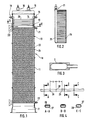
- the evaporative heat exchanger 10 has a housing 11 in which an active liquid cooling circuit 12, for example for lubricating oil, and an active liquid cooling circuit 13, for example hydraulic oil, are arranged one behind the other in the longitudinal direction of the evaporative heat exchanger.
- an active liquid cooling circuit 12 for example for lubricating oil
- an active liquid cooling circuit 13 for example hydraulic oil
- a space 14 is formed in FIG. 1 on the left-hand side, in which medium to be evaporated, for example water, is supplied via inlet valves 15 and 16 from a storage container, not shown.
- medium to be evaporated for example water
- the other end of the approximately rectangular housing 11 is formed by a steam outlet mouth 17.
- the active cooling circuit 12 has an insert 18 indicated at the top in FIG. 1 and an outlet 19 indicated at the bottom in FIG. 1. Between the inlet 18 and the outlet 19, the coolant channels 20 run perpendicular to the flow direction of the medium to be evaporated.
- the active cooling circuit 13 has an inlet 21 and an outlet 22 as well as folded coolant channels 23 and 24.
- FIG. 3 shows an enlarged detail from FIG. 1 in the region of a distribution pipe 26 extending perpendicular to a pipe 25 of the inlet 21.
- the coolant of the active cooling circuit 13 flows from the distribution pipe 26 into the coolant channels 21 and 24.
- the coolant channels 24 and 23 are arranged within the housing 11 in the main flow direction of the medium to be evaporated and are arranged one below the other and perpendicular to the aforementioned main flow direction and consist of flattened tubes 27.
- FIG. 4 shows a section of such a flattened tube 27 in an enlarged view lying tubes have, as can be seen from Fig. 1, a parallel folding by about 30 ° to the main flow direction of the medium to be owed.
- two tubes 23, 24 lying next to one another each fold in opposite directions by approximately 30 ° in the direction of the main flow direction of the medium to be evaporated.
- the tubes form parallel flow deflecting surfaces which inhibit the flow.
- FIG. 4 shows a section 27 of the tubes 23 and 24 shown.
- the different sections A-A, B-B, C-C illustrate the tube cross-section.
- the tube section 27 consists essentially of a flattened tube, the inner diameter of which was 2.51 mm in the illustrated embodiment.
- the pipe section has indentations 28, which contribute to good thermal radiation behavior.
- the indentations 28 are alternately provided at equal intervals a on the top and bottom of the flattened tube 27. In a preferred embodiment, the distance a is approximately 5.3 mm.
- the cross section formed by the indentation 28 of the tube 27 can be seen from the cross-sectional views AA, CC.
- a preferred length for the tube of a coolant channel 23 or 24 shown is 1.2 m.
- the bundle-like structure of the active cooling circuit 13 is composed of 80 individual tubes.
- the volume flow of the medium to be evaporated is controlled with the aid of the inlet valves 15, 16, which in turn are actuated by servomotors (not shown).
- the medium to be evaporated is pressed into the space 14 through the inlet valves 15, 16 at a delivery pressure which is above its triple point, for example about 6 m bar for water. Due to the lower pressure prevailing here, a small part of the medium to be evaporated, based on water at approx. 8% mass, evaporates adiabatically at approx. 60 ° C feed temperature and cools the medium to be evaporated.
- the gas resulting from this first evaporation process in room 14 mixes with the remaining liquid drops and forms a two-phase flow accelerated by the gas expansion, the volume-related components of which are heated when using 25 ° C.
- Water at low pressure is about 99.95% water vapor and 0.05% water.
- the cooling circuit 13 can consist of several separate cooling liquid circuits in a manner not shown.
- the coolant in the aforementioned cooling circuits is transported in heat known per se from heat generators to the coolant channels which form the actual evaporative heat exchanger, heat being transferred to the medium to be evaporated on the surfaces of the coolant channels and the medium being evaporated.
- the steam generated by the heat exchange then leaves the spacecraft via the steam outlet mouth 17.
- the liquid drops entrained in the gas phase experience a deviation from the gas flow direction due to their inertia and collide with nearby coolant channel outer walls. There they form a liquid film with other drops of liquid that partially evaporates. At the folds of the coolant channels, new drops form from the undevaporated residues of the moisture film, which are entrained by the two-phase flow and are stored again at another location on an outer surface of the coolant channel wall.
- the flow is divided into different flow sections with changing flow directions particularly intensive contacting of the medium to be evaporated, which leads to complete evaporation with excellent heat transfer efficiency.
Landscapes
- Engineering & Computer Science (AREA)
- Toxicology (AREA)
- Remote Sensing (AREA)
- Environmental & Geological Engineering (AREA)
- Environmental Sciences (AREA)
- General Health & Medical Sciences (AREA)
- Health & Medical Sciences (AREA)
- Life Sciences & Earth Sciences (AREA)
- Biodiversity & Conservation Biology (AREA)
- Aviation & Aerospace Engineering (AREA)
- Physics & Mathematics (AREA)
- Thermal Sciences (AREA)
- Mechanical Engineering (AREA)
- General Engineering & Computer Science (AREA)
- Heat-Exchange Devices With Radiators And Conduit Assemblies (AREA)
Applications Claiming Priority (2)
| Application Number | Priority Date | Filing Date | Title |
|---|---|---|---|
| DE19883832001 DE3832001C1 (fr) | 1988-09-21 | 1988-09-21 | |
| DE3832001 | 1988-09-21 |
Publications (2)
| Publication Number | Publication Date |
|---|---|
| EP0361009A1 true EP0361009A1 (fr) | 1990-04-04 |
| EP0361009B1 EP0361009B1 (fr) | 1992-04-22 |
Family
ID=6363375
Family Applications (1)
| Application Number | Title | Priority Date | Filing Date |
|---|---|---|---|
| EP19890113493 Expired - Lifetime EP0361009B1 (fr) | 1988-09-21 | 1989-07-22 | Echangeur de chaleur à évaporation |
Country Status (2)
| Country | Link |
|---|---|
| EP (1) | EP0361009B1 (fr) |
| DE (1) | DE3832001C1 (fr) |
Cited By (1)
| Publication number | Priority date | Publication date | Assignee | Title |
|---|---|---|---|---|
| EP0405078A1 (fr) * | 1989-06-30 | 1991-01-02 | ERNO Raumfahrttechnik Gesellschaft mit beschränkter Haftung | Echangeur de chaleur à évaporation |
Families Citing this family (2)
| Publication number | Priority date | Publication date | Assignee | Title |
|---|---|---|---|---|
| DE4136969A1 (de) * | 1991-11-11 | 1993-05-13 | Erno Raumfahrttechnik Gmbh | Verdampfungswaermetauscher |
| DE29510720U1 (de) * | 1995-07-01 | 1995-09-07 | BDAG Balcke-Dürr AG, 40882 Ratingen | Wärmetauscher |
Citations (8)
| Publication number | Priority date | Publication date | Assignee | Title |
|---|---|---|---|---|
| US2278242A (en) * | 1940-12-28 | 1942-03-31 | Gen Electric | Evaporative cooler |
| US2570247A (en) * | 1945-01-05 | 1951-10-09 | Niagara Blower Co | Condenser |
| FR1539635A (fr) * | 1966-10-28 | 1968-09-20 | Dispositif perfectionné de refroidissement de fluides | |
| DE2033206A1 (de) * | 1969-07-17 | 1971-02-04 | Munters Carl Georg, Stocksund (Schweden) | Verfahren zum Trocknen von Luft so wie hierfür bestimmte Vorrichtung |
| US3969448A (en) * | 1972-03-01 | 1976-07-13 | Basil Gilbert Alfred Lund | Heat exchangers |
| US4434112A (en) * | 1981-10-06 | 1984-02-28 | Frick Company | Heat transfer surface with increased liquid to air evaporative heat exchange |
| DE3718873C1 (en) * | 1987-06-05 | 1988-11-10 | Erno Raumfahrttechnik Gmbh | Evaporative cooler |
| EP0272766B1 (fr) * | 1986-12-02 | 1991-11-06 | Evapco International, Inc. | Assemblage de serpentins de tubes elliptiques pour échangeur de chaleur à évaporation |
-
1988
- 1988-09-21 DE DE19883832001 patent/DE3832001C1/de not_active Expired - Lifetime
-
1989
- 1989-07-22 EP EP19890113493 patent/EP0361009B1/fr not_active Expired - Lifetime
Patent Citations (8)
| Publication number | Priority date | Publication date | Assignee | Title |
|---|---|---|---|---|
| US2278242A (en) * | 1940-12-28 | 1942-03-31 | Gen Electric | Evaporative cooler |
| US2570247A (en) * | 1945-01-05 | 1951-10-09 | Niagara Blower Co | Condenser |
| FR1539635A (fr) * | 1966-10-28 | 1968-09-20 | Dispositif perfectionné de refroidissement de fluides | |
| DE2033206A1 (de) * | 1969-07-17 | 1971-02-04 | Munters Carl Georg, Stocksund (Schweden) | Verfahren zum Trocknen von Luft so wie hierfür bestimmte Vorrichtung |
| US3969448A (en) * | 1972-03-01 | 1976-07-13 | Basil Gilbert Alfred Lund | Heat exchangers |
| US4434112A (en) * | 1981-10-06 | 1984-02-28 | Frick Company | Heat transfer surface with increased liquid to air evaporative heat exchange |
| EP0272766B1 (fr) * | 1986-12-02 | 1991-11-06 | Evapco International, Inc. | Assemblage de serpentins de tubes elliptiques pour échangeur de chaleur à évaporation |
| DE3718873C1 (en) * | 1987-06-05 | 1988-11-10 | Erno Raumfahrttechnik Gmbh | Evaporative cooler |
Cited By (1)
| Publication number | Priority date | Publication date | Assignee | Title |
|---|---|---|---|---|
| EP0405078A1 (fr) * | 1989-06-30 | 1991-01-02 | ERNO Raumfahrttechnik Gesellschaft mit beschränkter Haftung | Echangeur de chaleur à évaporation |
Also Published As
| Publication number | Publication date |
|---|---|
| DE3832001C1 (fr) | 1990-04-12 |
| EP0361009B1 (fr) | 1992-04-22 |
Similar Documents
| Publication | Publication Date | Title |
|---|---|---|
| DE3650658T2 (de) | Wärmetauscher | |
| EP0541927B1 (fr) | Echangeur de chaleur à évaporation | |
| DE69926600T2 (de) | Verbesserter Verdampfereintritt | |
| DE4240082C1 (de) | Wärmerohr | |
| DE3810128C1 (fr) | ||
| DE2442420C3 (de) | Desublimator für die Gewinnung von Sublimationsprodukten, insbesondere von Phthalsäureanhydrid, aus Reaktionsgasen | |
| DE2309937A1 (de) | Waermeaustauscher | |
| DE69523639T2 (de) | Wärmetauscher | |
| EP0405078B1 (fr) | Echangeur de chaleur à évaporation | |
| DE3803534C1 (fr) | ||
| DE2450093A1 (de) | Waermetauscher | |
| DE4200688C1 (fr) | ||
| DE69007709T2 (de) | Stapelverdampfer. | |
| EP2696159A1 (fr) | Échangeur thermique et procédé de mise en réseau d'échangeurs thermiques | |
| EP0361009B1 (fr) | Echangeur de chaleur à évaporation | |
| DE3718873C1 (en) | Evaporative cooler | |
| DE19953612A1 (de) | Wärmetauscher | |
| DE2524080A1 (de) | Waermeuebertrager, in dem ein dampffoermiges medium unter waermeabgabe an ein anderes medium kondensiert | |
| DE3023094C2 (de) | Vorrichtung zum Erzeugen von Dampf | |
| DE3035306C2 (de) | Dampfkondensator | |
| DE69102879T2 (de) | Gaskühler zur wärmeübertragung durch konvektion. | |
| EP0532852B1 (fr) | Echangeur de chaleur à évaporation | |
| EP0687878B1 (fr) | Tour de refroidissement à évaporation | |
| EP0209107B1 (fr) | Echangeur de chaleur avec tirant de délestage pour les tubes d'échange de chaleur | |
| DE3323987A1 (de) | Mehrstufiger waermetauscher |
Legal Events
| Date | Code | Title | Description |
|---|---|---|---|
| PUAI | Public reference made under article 153(3) epc to a published international application that has entered the european phase |
Free format text: ORIGINAL CODE: 0009012 |
|
| AK | Designated contracting states |
Kind code of ref document: A1 Designated state(s): FR IT |
|
| 17P | Request for examination filed |
Effective date: 19900330 |
|
| 17Q | First examination report despatched |
Effective date: 19910418 |
|
| GRAA | (expected) grant |
Free format text: ORIGINAL CODE: 0009210 |
|
| AK | Designated contracting states |
Kind code of ref document: B1 Designated state(s): FR IT |
|
| ITF | It: translation for a ep patent filed | ||
| ET | Fr: translation filed | ||
| PLBE | No opposition filed within time limit |
Free format text: ORIGINAL CODE: 0009261 |
|
| STAA | Information on the status of an ep patent application or granted ep patent |
Free format text: STATUS: NO OPPOSITION FILED WITHIN TIME LIMIT |
|
| 26N | No opposition filed | ||
| PGFP | Annual fee paid to national office [announced via postgrant information from national office to epo] |
Ref country code: FR Payment date: 19990427 Year of fee payment: 11 |
|
| PG25 | Lapsed in a contracting state [announced via postgrant information from national office to epo] |
Ref country code: FR Free format text: LAPSE BECAUSE OF NON-PAYMENT OF DUE FEES Effective date: 20010330 |
|
| REG | Reference to a national code |
Ref country code: FR Ref legal event code: ST |
|
| PG25 | Lapsed in a contracting state [announced via postgrant information from national office to epo] |
Ref country code: IT Free format text: LAPSE BECAUSE OF NON-PAYMENT OF DUE FEES;WARNING: LAPSES OF ITALIAN PATENTS WITH EFFECTIVE DATE BEFORE 2007 MAY HAVE OCCURRED AT ANY TIME BEFORE 2007. THE CORRECT EFFECTIVE DATE MAY BE DIFFERENT FROM THE ONE RECORDED. Effective date: 20050722 |