EP0361013B1 - Module moteur pas à pas, train d'engrenage universel pour instrument-bracelet - Google Patents
Module moteur pas à pas, train d'engrenage universel pour instrument-bracelet Download PDFInfo
- Publication number
- EP0361013B1 EP0361013B1 EP89113652A EP89113652A EP0361013B1 EP 0361013 B1 EP0361013 B1 EP 0361013B1 EP 89113652 A EP89113652 A EP 89113652A EP 89113652 A EP89113652 A EP 89113652A EP 0361013 B1 EP0361013 B1 EP 0361013B1
- Authority
- EP
- European Patent Office
- Prior art keywords
- frame plate
- stepping motor
- combination according
- input
- terminals
- Prior art date
- Legal status (The legal status is an assumption and is not a legal conclusion. Google has not performed a legal analysis and makes no representation as to the accuracy of the status listed.)
- Expired - Lifetime
Links
Images


Classifications
-
- G—PHYSICS
- G04—HOROLOGY
- G04C—ELECTROMECHANICAL CLOCKS OR WATCHES
- G04C3/00—Electromechanical clocks or watches independent of other time-pieces and in which the movement is maintained by electric means
- G04C3/008—Mounting, assembling of components
Definitions
- This invention relates generally to wrist instruments with analog hands driven by a stepping motor and gear train and carrying out timekeeping as well as other functions. More particularly, the invention relates to a universal stepping motor/gear train module for use in a combined function wrist instrument.
- Electronic wristwatches are well known which have analog hands driven by a stepping motor through a speed reducing gear train.
- Such watches always include as part of the movement a printed circuit board which serves as a mounting platform and interconnects necessary electrical components including an integrated circuit, quartz crystal, and various discrete components such as transistors and capacitors.
- the movements also generally include provision for insertion of a button-type energy cell and spring contact switches which are connected to terminals on the circuit board.
- quartz analog watches include provision for digital timekeeping and to include a digital opto-electric display in combination with the analog hand display, this being sometimes called a "combo" watch.
- An example of a combo watch is seen in U.S. Patent 4,236,240 (& GB-A-2 032 146) in which stepping motor and gear train are assembled at an eight o'clock location in a recess of a support frame, and wherein a circuit board is disposed elsewhere in the movement in the same plane with liquid crystal display on side and an energy cell on the other.
- the stepping motor and gear train, together with time setting stem are assembled piece by piece at the time the overall movement is assembled.
- Watches have also been proposed in combination with calculators, radio transmitters, radio receivers, thermometers, and many other electronic devices, some of which use elements in common with the elements of an electronic watch and all of which occupy space inside the case of the wrist instrument.
- one object of the present is to provide an improved universal stepping motor/gear train module of minimum size and with a minimum number of components.
- Another object of the invention is to provide such a universal module which is preassembled and especially adapted to occupy only a portion of a case of a wrist instrument along with other electronic devices connected thereto.
- the invention comprises a universal stepping motor/gear train module for a wrist instrument having a frame plate, a bridge plate attached thereto and spaced therefrom, a stepping motor comprising rotor and stator disposed between said plates, a reduction gear train having gear members coupled to be drived by the rotor and having coaxial output members adapted to receive analog hands, said seat members being rotatably disposed between said plates, said frame plate defining a recess large enough to receive at least a portion of a button energy cell and characterized by an input/output circuit board disposed in said frame plate and having a pair of power supply terminals thereon, and first and second spring contact connectors having ends adapted to contact the terminals of the button energy cell and extending between the recess and the power supply terminals on the input/output circuit board, whereby power may either be supplied to said input/output circuit board directly from said power supply terminals or from said energy cell.
- the input/output circuit board may include other terminals for a
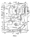
- a universal stepping/motor gear train module shown generally as 2 comprises a substantially rectangular frame plate 4 of nonmagnetic material such as plastic, which serves as the basic structural member of the module and contains a number of holes serving as journal bearings for gear train members.
- a bridge plate 6 spans the frame plate and is spaced therefrom.
- Bridge plate 6 contains holes which serve as journal bearings for the opposite ends of the rotating gear members, and is fixed to the frame plate 4 by means of hooks 6a, 6b, and 6c which snap into recesses in the frame plate.
- Rotor 14 includes a bipolar permanent magnet 14a, gear pinion 14b, and opposed stems 14c, 14d journaled in holes in the frame plate and bridge plate respectively (see Figs. 1 and 2).
- Rotor 14 is disposed within a cylindrical well 4a in the frame formed by a cylindrical wall 4b which extends through the air gap between rotor 14 and stator 12.
- An intermediate wheel assembly 16 of plastic material has a gear wheel 16a meshing with pinion 14b, a pinion 16b, an extension 16c passing through a hole in the stator of the stepping motor, and opposed stems 16d, 16e journaled in the frame plate and bridge plate respectively.
- a number of coaxial rotatable output members adapted to receive the hands of the timepiece are journaled by means of a fixed center post 18 held in frame plate 4.
- Center post 18 is hollow and journals on its interior a second wheel assembly 20, having a "seconds" gear wheel 20a meshing with pinion 16b, a pinion 20b and a seconds shaft 20c adapted to receive a seconds hand.
- Journaled on the exterior of center post 18 is a center wheel 22 with a coaxial sleeve 22a adapted to receive a "minutes" hand (not shown).
- Coaxially journaled about sleeve 22a is a hour wheel 24 with a coaxial sleeve 24a adapted to receive "hours" hand (not shown).
- Seconds shaft 20c, sleeve 22a, and sleeve 24a are coaxial output members.
- a third wheel assembly 26 includes a third wheel gear 26a meshing with pinion 20b, a pinion 26b meshing with center wheel 22, a ring flange 26c journaled in the frame, and a stem 26d journaled in the bridge plate.
- a frictional slip clutch 27 permits pinion 26b to turn when wheel 26a is locked, as will be explained later.
- the foregoing members comprise a stepping motor and a reduction gear train driven by the rotor or the stepping motor and having coaxial output members adapted to receive hands.
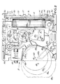
- a stepping motor and gear train is present in any quartz analog timepiece, but in accordance with the present invention is provided in a preassembled module of minimum size and arranged to fit below a much larger dial 28, portions of which are shown in phantom lines in Figs. 3 and 4.
- journal bearing holes such as 4c, 6d in the frame plate and bridge plate which are not used in the gear train. These holes is not material to the present invention, since they are used for an additional gear train in keeping with the universal nature of the module.
- an input/output board 30 is set perpendicular to the frame in opposed slots 4d, 4e.
- Input/output board 30 has a number of terminals on it which are adapted to receive external wiring connections. These include a pair of power supply terminals 32, 33, a pair of stepping motor input terminals 34, 35, a pair of time base input terminals 36, 37, and switching input terminals, one of which is seen at 38. Other terminals might be included to interface with discrete components which may be required for particular applications.
- the power supply terminals 32, 33 are tabs formed on the ends of spring contact connectors, which extend across the frame plate to also serve as contacts with an energy cell, which may or may not be used with the module.
- the power supply terminal 32 comprises one end of a spring contact connector 40, which has a terminating contact tab 40a, extending into the bottom of an energy cell recess 42.
- the spring contact connector is held in place by a post 44 which is integral with frame 4, and a pair of tabs 40c, 40b extending into slots of the frame on either side of the post.
- the power supply terminal 33 is part of a larger spring contact connector comprising a holding plate 46, which performs a great many functions, but pertinent to the present discussion includes a spring contact tab 46a extending into the battery recess 42. Another portion 46b of the holding plate serves as a detent spring.
- the spring tabs 40a, 46a function in the manner of normal spring contact tabs to make connection with the positive and negative terminals of a button-type energy cell when it is inserted into recess 42.
- recess 42 is large enough to receive only a portion of an energy cell, since in some cases the module will be operated without an energy cell.
- Recess 42 is also laid out in such a way as to accommodate varying diameter energy cells.
- the wall of the recess 42 comprises arcuate sections 42a, 42b, 42c with two different radii locating three different cell centers, such as 48, 49, 50.
- the phantom line circles 48a, 49a, 50a indicate how these varying diameter energy cells are accomodated within recess 42 and make contact with the spring contact terminals 40a, 46a.
- the pair of stepping motor terminals 34, 35 on the input/output board 30 are connected directly to the stepping motor coil 8 by leads 34a, 35a. They may be employed to direct external drive impulses to the coil to advance the hands, whether used for timekeeping or to display some other function.
- the time base input terminals 36, 37 may be employed to either supply an external time base connection from the board 30 with mounted integrated circuit, quartz crystal and oscillator capacitors to a separate device or to connect the board 30 with mounted integrated circuit to external quartz crystal and external oscillator capacitors which may optionally be mounted also on the board 30.
- the switching terminal 38 which is representative of other switching terminals as well, is employed either to connect to a manual actuator on the wrist instrument or to introduce an external switching signal.
- the universal module also includes a manual setting stem 52, which is both rotatable and slidable within frame plate 4, and held by spring portion 46b in detend grooves 52a.
- Loosely disposed on stem 52 is a setting pinion having teeth engaged with center wheel 22 at all times.
- Stem 52 includes a terminating section 52b which has a diameter such that it will frictionally engage the interior of setting pinion 54 when the stem 52 is pulled out.
- the end of stem portion 52b also engages a stop lever 56 and holds it against the bias of a spring finger 56a.
- Stop lever 56 also includes a spring contact switching portion 56b and a shaft rotation stop portion 56c.
- a pin stop 58 in board 30 both physically stops the stop lever 56, as well as makes electrical contact.
- Operation of the stop lever is such that when the stem 52 is pulled out, the setting pinion 54 frictionally engages the stem and allows rotation of the stem to set the hands. At the same time, stop lever 56 is released, allowing portion 56c to lock a portion of the gear train including the stepping motor rotor and the seconds wheel.
- the frictional slip clutch 27 allows the minute and hour hand part of the gear train to rotate.
- coaxial output members 20c, 22a, 24a are not located in the center of the substantially rectangular frame, but are located at a point substantially to one side of the center of the frame plate, i.e. approximately midway between the center thereof and one of the edges.
- the stepping motor coil extends along one edge and the energy cell recess is disposed on the opposite edge, so that the gear members may be arranged with their axles in a line which runs more or less parallel to the coil of the stepping motor.
- Fig. 5 is a schematic representation of the input/output board 30.
- a quartz crystal timebase 62 for the alarm or annunciator, manual push button actuators 74, 76, one or more energy cells 78, and stepping motor and gear train 80.
- additional terminals 32-38 are provided on input/output board 30.
- the integrated circuit 60 and discrete components normally mounted on the board and shown in Fig. 5 may be partially or totally eliminated and furnished through external connections or from another electrical device inside the wrist instrument case. In the extreme case the terminals 32-38 are the only items on board 30.
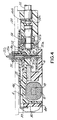
- Figs. 6-8 are representative arrangements.
- the module 2 is shown in a wrist instrument case 82 of minimum size.
- the module acts as an analog indicator for some purpose other than timekeeping such as temperature indicator.
- Power is supplied externally through terminals 32, 33 and stepping motor impulses which may also include reversing impulses are supplied externally through terminals 34, 35.
- module 2 is disposed within a wrist instrument case 84 along with another electrical device 86.
- An energy cell 88 supplies the power.
- Discrete components such as quartz crystal timebase 62, integrated circuit 60 and capacitor 64 are mounted on board 30. Electrical power is supplied from energy cell 88 also to the device 86 from the board terminals 32, 33.
- a more complex wrist instrument is disposed in case 90, with a more complex electrical device 92 and a large energy cell 94.
- the larger electrical device 92 contains the necessary elements for its own function as well as those of the stepping motor/gear train. Hence, it is provided with terminals which connect directly to terminals 32-37 on the input/output board 30.
- Figs. 6-8 in the circuit diagram of Fig. 5 are merely intended to show representative arrangements and flexibility of the universal stepping motor/gear train module. Because of the location of the coaxial output members off center in module 2, the module may be displaced to one side in the wrist instrument case to allow room for the other electrical devices such as 86, 92 shown in Figs. 7 and 8, while still keeping the center of the analog hands in the center of the wrist instrument.
Landscapes
- Physics & Mathematics (AREA)
- General Physics & Mathematics (AREA)
- Electromechanical Clocks (AREA)
Claims (14)
- Un module à moteur pas à pas, train d'engrenages universel pour un instrument de poignet, comprenant :- une plaque de base (4),- une plaque de pontage (6) fixée dessus et espacée de la plaque (4),- un moteur pas à pas comprenant un rotor (14) et un stator (12) disposés entre lesdites plaques,- un train d'engrenages réducteur comportant des pignons accouplés de façon à être entraînés par ledit rotor (14) et comportant des éléments de sortie coaxiaux (20c, 22a, 24a) adaptés pour recevoir des aiguilles, lesdits pignons étant disposés de façon tournante entre lesdites plaques (4, 6),- ladite plaque de base (4) définissant un évidement (42) suffisamment grand pour recevoir au moins une partie d'une pile-bouton, caractérisé par une plaquette à circuit d'entrée/sortie (30) disposée dans ladite plaque de base (4) et comportant une paire de bornes (32, 33) d'alimentation en courant, et des premier et second connecteurs de contact à ressorts (40, 46) comportant des extrémités adaptées pour entrer en contact avec les bornes de ladite pile-bouton et s'étendant entre ledit évidement (42) et lesdites bornes (32, 33) d'alimentation en courant sur la plaquette à circuit d'entrée/sortie (30), de telle sorte que du courant puisse être fourni à ladite plaquette à circuit d'entrée/sortie (30) directement à partir desdites bornes (32, 33) d'alimentation en courant ou bien à partir de ladite pile-bouton.
- La combinaison conforme à la revendication 1, dans laquelle lesdits éléments de sortie coaxiaux (20c, 22a, 24a) sont disposés sensiblement sur un côté du centre de ladite plaque de base (4), et dans laquelle ladite plaquette à circuit d'entrée/sortie (30) est disposée dans un plan sensiblement perpendiculaire à ceux contenant la plaque de base (4) et la plaque de pontage (6).
- La combinaison selon la revendication 1, dans laquelle ledit évidement (42) de pile-bouton est adapté pour recevoir des parties de la circonférence de piles de différents diamètres.
- La combinaison selon la revendication 1, dans laquelle ladite plaquette à circuit d'entrée/sortie (30) comporte également au moins un circuit intégré et est pourvue au moins d'une borne de commutation adaptée pour être reliée à un autre dispositif (86, 92) prévu dans ledit instrument de poignet, ladite borne de commutation étant également reliée audit circuit intégré.
- La combinaison selon la revendication 1, dans laquelle ladite plaque de base (4) est sensiblement rectangulaire et ledit moteur pas à pas comporte un enroulement s'étendant parallèlement et adjacent à un premier bord de ladite plaque de base (4).
- La combinaison selon la revendication 1, dans laquelle ladite plaque de base (4) est sensiblement rectangulaire et lesdits éléments de sortie coaxiaux (20c, 22a, 24a) sont situés sensiblement à mi-distance entre le centre de la plaque de base (4) et un second bord de celle-ci.
- La combinaison selon la revendication 1, dans laquelle au moins un desdits pignons s'étend entre lesdites plaques (4, 6) à travers un trou défini dans ledit stator (12).
- La combinaison selon la revendication 1, dans laquelle ledit évidement (42) définit plusieurs surfaces incurvées comportant différents centres adaptés pour correspondre à des piles-bouton de différents diamètres.
- La combinaison selon la revendication 1, dans laquelle ladite plaquette à circuit d'entrée/sortie (30) comporte deux bornes (34, 35) du moteur pas à pas et dans laquelle ledit moteur pas à pas comporte un enroulement relié directement à ladite paire de bornes de moteur pas à pas (34, 35) prévues sur ladite plaquette de circuit d'entrée/sortie (30) de façon qu'un autre signal produit à l'extérieur du module puisse être appliqué auxdites bornes (34, 35) du moteur pas à pas afin d'exciter pas à pas ledit moteur.
- La combinaison selon la revendication 1, dans laquelle ladite plaque de base (4) est sensiblement rectangulaire, ledit moteur pas à pas comporte un enroulement s'étendant parallèlement à un premier bord de ladite plaque de base (4), lesdits éléments de sortie coaxiaux (20c, 22a, 24a) étant situés entre un centre de ladite plaque de base (4) et un second bord de cette dernière perpendiculaire audit premier bord, ledit évidement (42) étant défini dans un troisième bord opposé audit premier bord.
- La combinaison selon la revendication 1, dans laquelle une tige de commande (52) manoeuvrable manuellement, comportant des éléments d'encliquetage et pourvue d'une roue dentée, est adaptée pour amener sélectivement cette roue dentée en prise avec un desdits pignons de façon à faire tourner manuellement ledit pignon, et dans laquelle un desdits connecteurs de contact à ressorts (40, 46) comprend un ressort d'encliquetage (46b) coopérant avec lesdits éléments d'encliquetage de ladite tige de commande (52).
- La combinaison selon la revendication 11, dans laquelle ledit module comprend en outre un levier d'arrêt (56) sollicité par ressort et comportant une première partie sollicitée pour entrer en contact frottant et maintenir un second pignon, et comportant une seconde partie répondant à un mouvement de ladite tige de commande (52) pour réduire une activation et une désactivation de ladite première partie.
- La combinaison selon la revendication 1, dans laquelle ladite plaque de base (4) est formée d'un matériau non magnétique et est sensiblement rectangulaire, et dans laquelle ladite plaque de pontage (6) est formée d'un matériau non magnétique et s'étend entre deux bords opposés de ladite plaque de base (4) en définissant une paire de branches élastiques opposées (6a, 6b, 6c) adaptées pour s'accrocher sur les bords opposés de la plaque de base (4) afin de maintenir la plaque de pontage (6) sur la plaque de base (4).
- La combinaison selon la revendication 1, dans laquelle ladite plaquette à circuit d'entrée/sortie (30) comprend un circuit intégré et une paire de bornes d'entrée de base de temps pour une connexion avec un autre dispositif prévu dans ledit instrument de poignet, ledit circuit intégré étant également relié auxdites bornes d'entrée de base de temps.
Applications Claiming Priority (2)
| Application Number | Priority Date | Filing Date | Title |
|---|---|---|---|
| US07/250,184 US4886988A (en) | 1988-09-28 | 1988-09-28 | Universal stepping motor/gear train module for a wrist instrument |
| US250184 | 1988-09-28 |
Publications (3)
| Publication Number | Publication Date |
|---|---|
| EP0361013A2 EP0361013A2 (fr) | 1990-04-04 |
| EP0361013A3 EP0361013A3 (fr) | 1991-09-25 |
| EP0361013B1 true EP0361013B1 (fr) | 1993-03-24 |
Family
ID=22946642
Family Applications (1)
| Application Number | Title | Priority Date | Filing Date |
|---|---|---|---|
| EP89113652A Expired - Lifetime EP0361013B1 (fr) | 1988-09-28 | 1989-07-25 | Module moteur pas à pas, train d'engrenage universel pour instrument-bracelet |
Country Status (3)
| Country | Link |
|---|---|
| US (1) | US4886988A (fr) |
| EP (1) | EP0361013B1 (fr) |
| DE (1) | DE68905560T2 (fr) |
Families Citing this family (5)
| Publication number | Priority date | Publication date | Assignee | Title |
|---|---|---|---|---|
| CH690881A5 (fr) * | 1996-12-04 | 2001-02-15 | Ebauchesfabrik Eta Ag | Transducteur électromécanique monophasé et dispositif électromécanique comprenant au moins un tel transducteur. |
| US6441326B1 (en) * | 1999-08-02 | 2002-08-27 | France/Scott Fetzer Company | Timer |
| JP4244643B2 (ja) * | 2003-01-28 | 2009-03-25 | セイコーエプソン株式会社 | クロノグラフ付時計 |
| DE602004018429D1 (de) * | 2003-01-28 | 2009-01-29 | Seiko Epson Corp | Multifunktions-armbanduhr |
| JP2006226923A (ja) * | 2005-02-21 | 2006-08-31 | Seiko Instruments Inc | 電子時計 |
Family Cites Families (8)
| Publication number | Priority date | Publication date | Assignee | Title |
|---|---|---|---|---|
| US3748845A (en) * | 1971-12-02 | 1973-07-31 | Bulova Watch Co Inc | Electronic system module for crystal-controlled watch |
| DE2632303C3 (de) * | 1976-07-17 | 1982-09-16 | Gebrüder Junghans GmbH, 7230 Schramberg | Batteriebetriebene elektronische Uhr |
| JPS5543435A (en) * | 1978-09-22 | 1980-03-27 | Citizen Watch Co Ltd | Electronic watch |
| US4264969A (en) * | 1979-06-28 | 1981-04-28 | Bulova Watch Company, Inc. | Standardized electronic watch movement |
| JPS57211084A (en) * | 1981-06-19 | 1982-12-24 | Citizen Watch Co Ltd | Movement structure of electronic watch |
| JPS59104586A (ja) * | 1982-12-07 | 1984-06-16 | Seiko Epson Corp | コンビネ−シヨン時計のモジユ−ル構造 |
| DE3346388A1 (de) * | 1983-12-22 | 1985-07-04 | Hans-Joachim 6109 Mühltal Lühr | Verfahren und vorrichtung zur stromversorgung von digitaluhren |
| JPH0512792Y2 (fr) * | 1987-03-30 | 1993-04-02 |
-
1988
- 1988-09-28 US US07/250,184 patent/US4886988A/en not_active Expired - Fee Related
-
1989
- 1989-07-25 EP EP89113652A patent/EP0361013B1/fr not_active Expired - Lifetime
- 1989-07-25 DE DE8989113652T patent/DE68905560T2/de not_active Expired - Fee Related
Also Published As
| Publication number | Publication date |
|---|---|
| DE68905560D1 (de) | 1993-04-29 |
| EP0361013A3 (fr) | 1991-09-25 |
| US4886988A (en) | 1989-12-12 |
| EP0361013A2 (fr) | 1990-04-04 |
| DE68905560T2 (de) | 1993-07-01 |
Similar Documents
| Publication | Publication Date | Title |
|---|---|---|
| JP2010060355A (ja) | 情報表示装置および電子時計 | |
| US4426159A (en) | Electronic time keeping device | |
| EP0361013B1 (fr) | Module moteur pas à pas, train d'engrenage universel pour instrument-bracelet | |
| GB2097972A (en) | Stepping motor timepiece | |
| EP0493613A1 (fr) | Assemblage pour piece d'horlogerie du type cadran a aiguilles, procede de construction de celle-ci ainsi que piece d'horlogerie de ce type | |
| US4666311A (en) | Electronic timepiece with analogue display | |
| US4794576A (en) | Combination electrical contact member and braking member for a timepiece | |
| CA1330707C (fr) | Module universel train d'engrenages/moteur pas-a-pas pour instrument au poignet | |
| WO1996039649A1 (fr) | Horloge portant des indications sur des activites quotidiennes | |
| CN108369401A (zh) | 混合型行针表 | |
| JPH0226074Y2 (fr) | ||
| CN214795589U (zh) | 同轴异步混合式一体化石英手表机芯及手表 | |
| US5155711A (en) | Movement subassembly for a three and two hand timepiece using common piece parts | |
| JP2988954B2 (ja) | 指針式多機能時計 | |
| JPH0439593Y2 (fr) | ||
| JPH01291192A (ja) | 指針式世界時計 | |
| JPH0539509Y2 (fr) | ||
| JPS598235Y2 (ja) | 全電子式時計 | |
| JP3571941B2 (ja) | 電子時計 | |
| JPH0353190Y2 (fr) | ||
| JPS6117312B2 (fr) | ||
| JPS61147179A (ja) | アラ−ム付アナログ腕時計 | |
| JPH0342392Y2 (fr) | ||
| JPS6237190Y2 (fr) | ||
| JP2709847B2 (ja) | 電子データディスプレイセンターの製造方法及び電子データディスプレイセンター |
Legal Events
| Date | Code | Title | Description |
|---|---|---|---|
| PUAI | Public reference made under article 153(3) epc to a published international application that has entered the european phase |
Free format text: ORIGINAL CODE: 0009012 |
|
| AK | Designated contracting states |
Kind code of ref document: A2 Designated state(s): CH DE FR GB LI |
|
| PUAL | Search report despatched |
Free format text: ORIGINAL CODE: 0009013 |
|
| AK | Designated contracting states |
Kind code of ref document: A3 Designated state(s): CH DE FR GB LI |
|
| 17P | Request for examination filed |
Effective date: 19911012 |
|
| 17Q | First examination report despatched |
Effective date: 19920408 |
|
| GRAA | (expected) grant |
Free format text: ORIGINAL CODE: 0009210 |
|
| AK | Designated contracting states |
Kind code of ref document: B1 Designated state(s): CH DE FR GB LI |
|
| PG25 | Lapsed in a contracting state [announced via postgrant information from national office to epo] |
Ref country code: FR Effective date: 19930324 |
|
| REF | Corresponds to: |
Ref document number: 68905560 Country of ref document: DE Date of ref document: 19930429 |
|
| PGFP | Annual fee paid to national office [announced via postgrant information from national office to epo] |
Ref country code: CH Payment date: 19930621 Year of fee payment: 5 |
|
| PGFP | Annual fee paid to national office [announced via postgrant information from national office to epo] |
Ref country code: GB Payment date: 19930713 Year of fee payment: 5 |
|
| EN | Fr: translation not filed | ||
| PGFP | Annual fee paid to national office [announced via postgrant information from national office to epo] |
Ref country code: DE Payment date: 19930818 Year of fee payment: 5 |
|
| PLBE | No opposition filed within time limit |
Free format text: ORIGINAL CODE: 0009261 |
|
| STAA | Information on the status of an ep patent application or granted ep patent |
Free format text: STATUS: NO OPPOSITION FILED WITHIN TIME LIMIT |
|
| 26N | No opposition filed | ||
| PG25 | Lapsed in a contracting state [announced via postgrant information from national office to epo] |
Ref country code: GB Effective date: 19940725 |
|
| PG25 | Lapsed in a contracting state [announced via postgrant information from national office to epo] |
Ref country code: LI Effective date: 19940731 Ref country code: CH Effective date: 19940731 |
|
| GBPC | Gb: european patent ceased through non-payment of renewal fee |
Effective date: 19940725 |
|
| REG | Reference to a national code |
Ref country code: CH Ref legal event code: PL |
|
| PG25 | Lapsed in a contracting state [announced via postgrant information from national office to epo] |
Ref country code: DE Effective date: 19950401 |