EP0361023A1 - Füllstandsmessgerät - Google Patents
Füllstandsmessgerät Download PDFInfo
- Publication number
- EP0361023A1 EP0361023A1 EP89114021A EP89114021A EP0361023A1 EP 0361023 A1 EP0361023 A1 EP 0361023A1 EP 89114021 A EP89114021 A EP 89114021A EP 89114021 A EP89114021 A EP 89114021A EP 0361023 A1 EP0361023 A1 EP 0361023A1
- Authority
- EP
- European Patent Office
- Prior art keywords
- measuring device
- oscillator
- dipole
- level
- capacitor
- Prior art date
- Legal status (The legal status is an assumption and is not a legal conclusion. Google has not performed a legal analysis and makes no representation as to the accuracy of the status listed.)
- Granted
Links
Images

Classifications
-
- G—PHYSICS
- G01—MEASURING; TESTING
- G01F—MEASURING VOLUME, VOLUME FLOW, MASS FLOW OR LIQUID LEVEL; METERING BY VOLUME
- G01F23/00—Indicating or measuring liquid level or level of fluent solid material, e.g. indicating in terms of volume or indicating by means of an alarm
- G01F23/22—Indicating or measuring liquid level or level of fluent solid material, e.g. indicating in terms of volume or indicating by means of an alarm by measuring physical variables, other than linear dimensions, pressure or weight, dependent on the level to be measured, e.g. by difference of heat transfer of steam or water
- G01F23/26—Indicating or measuring liquid level or level of fluent solid material, e.g. indicating in terms of volume or indicating by means of an alarm by measuring physical variables, other than linear dimensions, pressure or weight, dependent on the level to be measured, e.g. by difference of heat transfer of steam or water by measuring variations of capacity or inductance of capacitors or inductors arising from the presence of liquid or fluent solid material in the electric or electromagnetic fields
- G01F23/261—Indicating or measuring liquid level or level of fluent solid material, e.g. indicating in terms of volume or indicating by means of an alarm by measuring physical variables, other than linear dimensions, pressure or weight, dependent on the level to be measured, e.g. by difference of heat transfer of steam or water by measuring variations of capacity or inductance of capacitors or inductors arising from the presence of liquid or fluent solid material in the electric or electromagnetic fields for discrete levels
-
- A—HUMAN NECESSITIES
- A61—MEDICAL OR VETERINARY SCIENCE; HYGIENE
- A61M—DEVICES FOR INTRODUCING MEDIA INTO, OR ONTO, THE BODY; DEVICES FOR TRANSDUCING BODY MEDIA OR FOR TAKING MEDIA FROM THE BODY; DEVICES FOR PRODUCING OR ENDING SLEEP OR STUPOR
- A61M1/00—Suction or pumping devices for medical purposes; Devices for carrying-off, for treatment of, or for carrying-over, body-liquids; Drainage systems
- A61M1/36—Other treatment of blood in a by-pass of the natural circulatory system, e.g. temperature adaptation, irradiation ; Extra-corporeal blood circuits
- A61M1/3621—Extra-corporeal blood circuits
- A61M1/3624—Level detectors; Level control
-
- A—HUMAN NECESSITIES
- A61—MEDICAL OR VETERINARY SCIENCE; HYGIENE
- A61M—DEVICES FOR INTRODUCING MEDIA INTO, OR ONTO, THE BODY; DEVICES FOR TRANSDUCING BODY MEDIA OR FOR TAKING MEDIA FROM THE BODY; DEVICES FOR PRODUCING OR ENDING SLEEP OR STUPOR
- A61M2205/00—General characteristics of the apparatus
- A61M2205/33—Controlling, regulating or measuring
- A61M2205/3379—Masses, volumes, levels of fluids in reservoirs, flow rates
- A61M2205/3389—Continuous level detection
-
- Y—GENERAL TAGGING OF NEW TECHNOLOGICAL DEVELOPMENTS; GENERAL TAGGING OF CROSS-SECTIONAL TECHNOLOGIES SPANNING OVER SEVERAL SECTIONS OF THE IPC; TECHNICAL SUBJECTS COVERED BY FORMER USPC CROSS-REFERENCE ART COLLECTIONS [XRACs] AND DIGESTS
- Y10—TECHNICAL SUBJECTS COVERED BY FORMER USPC
- Y10S—TECHNICAL SUBJECTS COVERED BY FORMER USPC CROSS-REFERENCE ART COLLECTIONS [XRACs] AND DIGESTS
- Y10S128/00—Surgery
- Y10S128/13—Infusion monitoring
Definitions
- the invention relates to a level measuring device according to the preamble of claim 1.
- optical measuring methods which take advantage of the fact that blood absorbs light due to its dark color, so that the angle of refraction at the interfaces changes when blood is present.
- optical methods it is disadvantageous that different mechanical sensor attachments are used for different blood reservoirs conditions are required.
- oxygenators the optical method can only be used if there is already blood in the oxygenator, whereas clear liquids are recognized as air.
- the object of the invention is to provide a fill level measuring device for liquid reservoirs, in particular for blood reservoirs of human medical devices, which is largely insusceptible to faults and thus ensures safe operation and is easy and inexpensive to manufacture.
- the fill level measuring device has an oscillator which is set to an operating frequency of greater than or equal to 50 MHz and in whose circuit the component which responds to the fill level is arranged and which, when passing through a preset limit value, determines the phase or amplitude condition relevant for the oscillation of the oscillator changed.
- v means the factor by which the amplifier amplifies the input voltage Ue of the oscillator.
- the angle ⁇ is the value of the phase shift of the output voltage Ua, which is larger by a factor v than the input voltage Ue.
- the feedback of the oscillator receives the output voltage of the amplifier as input voltage and weakens the input voltage by the factor k and shifts it Phase of the signal around the angle ß.
- Equation (1) is called the amplitude condition.
- An oscillator only oscillates when the value of the amplitude condition is greater than or equal to 1.
- Equation (2) is called the phase condition and it means that an oscillation only occurs when the output voltage of the feedback device is in phase with the input voltage of the amplifier.
- a component is inserted at any point in the oscillator circuit that changes its value as a function of the fill level so that either the phase or the amplitude condition is no longer present, resulting in a structure that oscillates or not depending on the fill level.
- this component which reacts as a function of the fill level, is formed by a dipole, which is preferably arranged at the output of the feedback connector and is otherwise matched to the oscillation frequency of the oscillator. If the fill level is above the dipole, this can radiate energy into the liquid, which reduces the output voltage of the feedback device, so that the amplitude condition is no longer fulfilled, rather the product kv is less than 1, and consequently the oscillator does not oscillate when the fill level is above the safety level controlled by the dipole.
- the amplitude condition is fulfilled and the oscillator oscillates, which can be made perceptible in a suitable manner, in particular acoustically or optically, so that a corresponding level control can be carried out.
- the invention is particularly suitable for blood reservoirs in containers made of plastic or glass (no lead glass). It is also suitable for other water-based liquids, such as nutrient solutions, urine and the like, in particular wherever the contents of the container should not be in contact.
- a capacitor can be used, which is expediently installed in the feedback network of the oscillator circuit in such a way that it determines the phase position of the output signal. If it is further dimensioned so that the oscillation condition is only fulfilled if the fill level is higher than the liquid level caused by the position of the condenser, then a drop in the fill level below the position of the liquid level caused by the condenser causes a change in the phase condition, so that the addition of the phase shifts ⁇ and ⁇ is not equal to an integer multiple of ⁇ , so that when the limit value caused by the position of the capacitor is exceeded, the oscillator no longer oscillates and therefore a fill level regulation must be carried out.
- the dipole or the capacitor are expediently insulated from the outside environment in order to be influenced by condensation and the like. Exclude the like.
- the stripping is expediently carried out using plastic.
- Any material that allows the dipole or the capacitor to be held and attached to the wall of the blood reservoir is suitable as a carrier.
- the carrier must be flexible. It is expedient to use a material for printed circuits for this purpose, so that the oscillator can be integrated in the carrier material, ie in particular can be formed by a printed circuit. According to an alternative, the oscillator is designed to be removable and can be plugged onto plug contacts formed on the dipole or capacitor.
- the operating frequency is expediently a value of greater than or equal to 100 MHz and is in particular in the microwave range, which is advantageous for the dimensioning of the dipole or capacitor.
- the measuring device according to the invention is characterized in that it can be used for all plastics, but also for other materials, such as in particular glass and ceramics. Furthermore, the measuring device is very easy to manufacture, so that it is particularly suitable as a disposable product. The measuring device according to the invention is particularly notable for its immunity to interference, so that a very exact and reliable level measurement is possible.
- the choice of the operating frequency range means that interference due to interference frequencies, which can result from other devices operating in the OR area, is excluded.
- the reference numeral 1 represents a container serving as a blood reservoir, which can be used, for example, in connection with an oxygenator or the like. It applies in such a container primarily to maintain a certain level of blood, for example.
- the measuring device generally designated 2 in FIG. 1 is used for this purpose and is arranged at the level to be monitored or the liquid level.
- the liquid level currently prevailing in the container is designated by 3.
- the level to be monitored is shown schematically in dashed lines and designated 4.
- a dipole 5 is provided, to which an oscillator 6 can be connected.
- the oscillator 6 is connected via a line 7 to a corresponding evaluation device 8.
- Fig. 2 shows the measuring device equipped with a dipole in greater clarity. Thereafter, two metal surfaces 9 and 10, which form the dipole 5, are arranged side by side on a support designated 11, with which the dipole can be attached to the wall of the container 1.
- the carrier is coated on the side facing the wall of the container with an adhesive which, for reasons of protection, is covered on the outside by a removable film 12.
- Plug contacts 13 and 14 are formed on the metal surfaces 9 and 10 forming the dipole, onto which the oscillator 6 can be plugged.
- the oscillator is fixed, that is to say latently connected to the metal surfaces forming the dipole, in particular cast with the metal surfaces under the carrier material.
- the carrier 11 is formed from a material for printed circuits, so that the oscillator can be printed on the carrier.
- the dipole 5 is expediently stripped from the outside environment, which is why the dipole, which is also designed to be flexible, is encapsulated in plastic. This measure ensures that the operation is not caused by condensation and. Like. is disturbed.
- the limit value denoted by 4 there is no longer any reduction in the output voltage of the feedback device because the dipole cannot radiate any energy into the liquid, so that the amplitude condition is now fulfilled and the oscillator oscillates.
- the dipole is integrated in the oscillator circuit, the dipole being expediently arranged at the output of the feedback connector of the oscillator.
- a capacitor is used as a component that reacts to the level and is integrated in the oscillator circuit in such a way that the capacitor determines the phase position of the output signal of the oscillator and the capacitor is dimensioned such that the oscillation condition is only fulfilled when the level in the container is higher than the limit value denoted by 4, causes a drop in the level below the value denoted by 4 a change in the value relevant for the oscillation condition, ie the phase condition, so that the oscillator begins to oscillate when the fill level is lower than the limit value denoted by 4.
- This can also be made perceptible in a suitable manner, in particular optically or acoustically, so that a corresponding fill level control is started.
- the operating frequency of the oscillator is greater than or equal to 50 MHz, in particular greater than or equal to 100 MHz, and is preferably in the microwave range.
- the microwave range is particularly suitable because it allows the component which responds to the fill level to be dimensioned small, has the size of an adhesive plaster and can therefore be very easily attached to a container wall by means of a suitable carrier.
Landscapes
- Health & Medical Sciences (AREA)
- Physics & Mathematics (AREA)
- Engineering & Computer Science (AREA)
- Heart & Thoracic Surgery (AREA)
- Vascular Medicine (AREA)
- Fluid Mechanics (AREA)
- Biomedical Technology (AREA)
- Thermal Sciences (AREA)
- Cardiology (AREA)
- Power Engineering (AREA)
- Electromagnetism (AREA)
- Anesthesiology (AREA)
- General Physics & Mathematics (AREA)
- Hematology (AREA)
- Life Sciences & Earth Sciences (AREA)
- Animal Behavior & Ethology (AREA)
- General Health & Medical Sciences (AREA)
- Public Health (AREA)
- Veterinary Medicine (AREA)
- External Artificial Organs (AREA)
- Measurement Of Levels Of Liquids Or Fluent Solid Materials (AREA)
Abstract
Description
- Die Erfindung betrifft ein Füllstandmeßgerät gemäß dem Oberbegriff des Patentanspruches 1.
- Beispielsweise bei herzchirurgischen Operationen muß zwingend ausgeschaltet werden, daß dem Patienten aus dem Blutreservoir Luft anstelle von Blut gepumpt wird, weil bereits geringe Mengen an Luft genügen, um eine fatale Luftembolie herbeizuführen. So kann etwa ein verminderter venöser Fluß aus dem Patienten zu einem raschen Absinken des Niveaus im Blutreservoir eines Oxygenators führen, so daß eine stete Kontrolle des Flüssigkeitsniveaus während der Operation erforderlich ist.
- Es ist bereits, ein Unterschreiten eines Mindestfüllstandes über das Gewicht abzulesen, wobei dann jedoch die Waage absolut unempfindlich gegen alle äußeren Einflüsse sein muß, die das Gewicht verändern können, wie beispielsweise Lageänderung der Schläuche, Stöße gegen den Oxygenator und dergleichen mehr. In der Praxis führt ein solches Meßverfahren zu einem außerordentlich aufwendigen mechanischen Gerät, dessen Zuverlässigkeit zu wünschen übrig läßt.
- Schließlich sind optische Meßverfahren bekannt, bei denen man den Umstand ausnutzt, daß Blut aufgrund seiner dunklen Farbe Licht absorbiert, so daß sich bei Vorhandensein von Blut die Brechungswinkel an den Grenzflächen ändern. Bei diesen optischen Verfahren ist jedoch nachteilhaft, daß für unterschiedliche Blutreservoirs unterschiedliche mechanische Sensorbefestigun gen erforderlich sind. Bei einigen Oxygenatortypen kann das optische Verfahren nur dann angewandt werden, wenn bereits Blut im Oxygenator ist, klare Flüssigkeiten werden hingegen als Luft erkannt.
- Jüngere Entwicklungen arbeiten nach dem Ultraschallprinzip. Ein an der Wand des Blutreservoirs angebrachter Ultraschallsensor imitiert nach entsprechender elektrischer Anregung eine Schallwelle durch die Wandung des Oxygenators in dessen Inneres. Die Frequenz der Ultraschallwelle liegt hierbei im Bereich von ca. 2 MHz. Befindet sich Flüssigkeit im Oxygenator, so kann sich die Welle ausbreiten. Trifft sie auf eine Grenzfläche, so wird ein Teil der Welle reflektiert und läuft zurück zum Schallwandler, der mittlerweile als Empfänger geschaltet ist. Da die Amplitude der Schallwelle jedoch auf ihrem Weg durch das Blutreservoir sehr stark abgeschwächt wird, sind sehr empfindliche Verstärker erforderlich, so daß die Ultraschallverfahren enorm störanfällig sind. Ein weiterer Nachteil besteht darin, daß die Ultraschallverfahren nur für bestimmte Kunststoffarten, insbesondere Makrolon anwendbar sind, nicht jedoch für andere Materialien. Ferner können sich Störfaktoren über die Wandstärke ergeben, da bei großen Wandstärken Wandreflexionen auftreten, was zu unsicheren Zuständen führt. Ein weiterer Nachteil ist darin zu sehen, daß zur Ankuppelung des Sensors ein Ultraschallgel zum Zwecke der Energieübertragung auf die Wand des Blutreservoirs verwendet werden muß.
- Aufgabe der Erfindung ist es, ein Füllstandsmeßgerät für Flüssigkeitsreservoire, insbesondere für Blutreservoire von humanmedizinischen Geräten zu schaffen, welches weitgehend störunanfällig ist und damit eine sichere Arbeitsweise gewährleistet sowie einfach und kostengünstig herstellbar ist.
- Diese Aufgabe wird erfindungsgemäß durch die im kennzeichnenden Teil des Patentanspruchs 1 enthaltenen Merkmale gelöst, wobei zweckmäßige Weiterbildungen der Erfindung durch die in den Unteransprüchen enthaltenen Merkmale gekennzeichnet sind.
- Nach Maßgabe der Erfindung weist das Füllstandmeßgerät einen Oszillator auf, der auf eine Betriebsfrequenz von größer gleich 50 MHz eingestellt ist und in dessen Schaltung das füllstandsabhängig reagierende Bauteil angeordnet ist, welches bei Durchschreiten eines voreingestellten Grenzwerts die für die Schwingung des Oszillators maßgebliche Phasen- oder Amplitudenbedingung verändert.
- Die Erfindung macht sich den Umstand zu eigen, daß ein grundsätzlich aus einem Rückkoppler und Verstärker bestehender Oszillator dann schwingfähig ist, wenn zwei Bedingungen erfüllt sind, nämlich
- (1) kv = 1
- (2) α + β = nπ,
- Hierbei bedeutet v denjenigen Faktor, um den der Verstärker die Eingangsspannung Ue des Oszillators verstärkt. Der Winkel α ist der Wert der Phasenverschiebung der Ausgangsspannung Ua, die um den Faktor v größer als die Eingangsspannung Ue ist. Der Rückkoppler des Oszillators erhält als Eingangsspannung die Ausgangsspannung des Verstärkers und schwächt die Eingangsspannung um den Faktor k ab und verschiebt die Phase des Signals um den Winkel ß.
- Die Gleichung (1) wird als Amplitudenbedingung bezeichnet. Ein Oszillator schwingt nur dann, wenn der Wert der Amplitudenbedingung größer oder gleich 1 ist. Die Gleichung (2) wird als Phasenbedingung bezeichnet und sie besagt, daß eine Schwingung nur dann zustande kommt, wenn die Ausgangsspannung des Rückkopplers phasengleich mit der Eingangsspannung des Verstärkers ist. Erfindungsgemäß wird an einer beliebigen Stelle der Oszillatorschaltung ein Bauteil eingefügt, das seinen Wert füllstandsabhängig so ändert, daß entweder die Phasen- oder die Amplitudenbedingung nicht mehr gegeben ist, wodurch man ein Gebilde erhält, das je nach Füllstand schwingt oder nicht.
- In einer zweckmäßigen Ausgestaltungsform ist dieses füllstandsabhängig reagierende Bauteil durch einen Dipol gebildet, der vorzugsweise am Ausgang des Rückkopplers angeordnet wird und im übrigen auf die Schwingfrequenz des Oszillators abgeglichen ist. Ist der Füllstand über dem Dipol, so kann dieser Energie in die Flüssigkeit abstrahlen, wodurch sich die Ausgangsspannung des Rückkopplers mindert, so daß die Amplitudenbedingung nicht mehr erfüllt ist, vielmehr das Produkt kv kleiner 1 ist, mithin der Oszillator nicht schwingt, wenn der Füllstand über dem durch den Dipol kontrollierten Sicherheitsstand liegt. Sobald der Flüssigkeitsstand unter das Niveau des Dipols absinkt, ist die Amplitudenbedingung erfüllt und der Oszillator schwingt, was in geeigneter Weise, insbesondere akustisch oder optisch wahrnehmbar gemacht werden kann, so daß einen entsprechende Füllstandsregelung vorgenommen werden kann. Die Erfindung eignet sich insbesondere für Blutreservoire in Behältern aus Kunststoff oder Glas (kein Bleiglas). Sie eignet sich auch für andere Flüssigkeiten auf Wasserbasis, wie Nährlösungen, Urin und dgl., insbesondere überall dort, wo man mit dem Inhalt des Behälters nicht in Berührung kommen soll.
- Alternativ zum Dipol kann ein Kondensator verwendet werden, der zweckmäßigerweise in das Rückkoppelnetzwerk der Oszillatorschaltung so eingebaut wird, daß er bestimmend für die Phasenlage des Ausgangssignales ist. Wird er ferner so dimensioniert, daß die Schwingbedingung nur dann erfüllt ist, wenn der Füllstand höher als die durch die Lage des Kondensators bedingte Flüssigkeitshöhe ist, so bewirkt ein Abfallen des Füllstandes unter die durch den Kondensator bedingte Lage des Flüssigkeitsniveaus eine Änderung der Phasenbedingung, so daß die Addition aus den Phasenverschiebungen α und ß ungleich einem ganzzahligen Vielfachen von π wird, so daß bei Durchschreiten des durch die Lage des Kondensators bedingten Grenzwert der Oszillator nicht mehr schwingt und mithin eine Füllstandsregulierung vorgenommen werden muß.
- Zweckmäßigerweise sind der Dipol oder der Kondensator gegen die Außenumgebung isoliert, um eine Beeinflussung infolge von Kondenswasser u. dgl. auszuschließen. Zweckmäßigerweise erfolgt die Abisolierung durch Kunststoff. Als Träger eignet sich jedes Material, welches die Aufnahme des Dipols oder des Kondensators sowie dessen Befestigung an der Wand des Blutreservoirs ermöglicht. Der Träger muß hierbei flexibel sein. Es ist zweckmäßig, hierzu ein Material für gedruckte Schaltungen zu verwenden, so daß der Oszillator im Trägermaterial integriert, d.h. insbesondere durch eine gedruckte Schaltung gebildet sein kann. Nach einer Alternative ist der Oszillator abnehmbar ausgebildet und kann auf am Dipol oder Kondensator ausgebildete Steckkontakte aufgesteckt werden.
- Zweckmäßigerweise beträgt die Betriebsfrequenz einen Wert von größer gleich 100 MHz und liegt insbesondere im Mikrowellenbereich, was für die Dimensionierung des Dipols oder Kondensators von Vorteil ist.
- Insgesamt zeichnet sich das erfindungsgemäße Meßgerät dadurch aus, daß es für alle Kunststoffe verwendbar ist, aber auch für andere Materialien, wie insbesondere Glas und Keramik. Ferner ist das Meßgerät sehr einfach herstellbar, so daß es sich insbesondere als Wegwerfprodukt eignet. Im besonderen Maße zeichnet sich das erfindungsgemäße Meßgerät durch eine Störunempfindlichkeit aus, so daß eine sehr exakte und zuverlässige Füllstandsmessung möglich ist. Durch die Wahl des Betriebsfrequenzbereichs ist eine Beeinflussung infolge von Störfrequenzen ausgeschlossen, die sich aus weiteren im OP-Bereich arbeitenden Geräten ergeben können.
- Nachfolgend werden Ausführungsbeispiele der Erfindung anhand der Zeichnung beschrieben. Darin zeigen
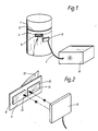
- Fig. 1 eine perspektivische Schemaansicht eines Meßgeräts an einem behälterartigen Blutreservoir,
- Fig. 2 eine Ansicht einer Ausführungsform des Meßgeräts sowie
- Fig. 3 eine schematische Ansicht einer weiteren Ausführungsform des Meßgeräts.
- In Fig. 1 ist mit dem Bezugszeichen 1 ein als Blutreservoir dienender Behälter dargestellt, der beispielsweise in Zusammenhang mit einem Oxygenator o. dgl. humanmedizinischem Gerät verwendbar ist. In einem solchen Behälter gilt es vornehmlich, eine bestimmte Füllstandshöhe von biespielsweise Blut aufrechtzuerhalten. Hierzu dient das in Fig. 1 allgemein mit 2 bezeichnete Meßgerät, das in Höhe der zu überwachenden Füllstandshöhe bzw. Flüssigkeitsniveaus angeordnet ist. Das momentan im Behälter vorherrschende Flüssigkeitsniveau ist mit 3 bezeichnet. Die zu überwachende Füllstandshöhe ist schematisch strichliert gekennzeichnet und mit 4 bezeichnet.
- Bei dem in Fig. 1 dargestellten Meßgerät 2 ist ein Dipol 5 vorgesehen, an den ein Oszillator 6 anschließbar ist. Der Oszillator 6 ist über eine Leitung 7 mit einem entsprechenden Auswertgerät 8 verbunden.
- Fig. 2 zeigt das mit einem Dipol ausgerüstete Meßgerät in größerer Deutlichkeit. Danach sind zwei Metallflächen 9 und 10, die den Dipol 5 bilden, nebeneinander auf einem mit 11 bezeichneten Träger angeordnet, mit dem der Dipol an der Wand des Behälters 1 befestigt werden kann. Im dargestellten Ausführungsbeispiel ist der Träger an der der Wand des Behälters zugewendeten Seite mit einem Kleber beschichtet, der aus Schutzgründen nach außen hin durch eine abziehbare Folie 12 abgedeckt ist. Auf den den Dipol bildenden Metallflächen 9 und 10 sind Steckkontakte 13 und 14 ausgebildet, auf die der Oszillator 6 aufsteckbar ist.
- Im Ausführungsbeispiel nach Fig. 3 ist der Oszillator fest, d.h. latent mit den den Dipol bildenden Metallflächen verbunden, insbesondere mit den Metallflächen unter dem Trägermaterial vergossen. In einer besonderen Ausgestaltung ist der Träger 11 aus einem Material für gedruckte Schaltungen ausgebildet, so daß der Oszillator auf den Träger aufgedruckt sein kann. Der Dipol 5 ist zweckmäßigerweise gegen die Außebumgebung hin abisoliert, wozu der gleichfalls wie der Träger flexibel ausgebildete Dipol mit Kunststoff umgossen ist. Durch diese Maßnahme ist sichergestellt, daß die Funktionsweise nicht durch Kondenswasser u. dgl. gestört wird.
- Der Dipol ist auf die Schwingfrequenz des Oszillators abgeglichen. Ist der Füllstand oberhalb der mit 4 bezeichneten Linie, als über dem Dipol, so kann der Dipol Energie in die Flüssigkeit abstrahlen, so daß ein Leistungsverbrauch stattfindet. Dadurch vermindert sich die Ausgangsspannung am Rückkoppler des Oszillalators und die für die Schwingung des Oszillators maßgebliche Amplitudenbedingung von kv = 1 ist nicht erfüllt, so daß der Oszillator nicht schwingt. Mit Durchschreiten des mit 4 bezeichneten Grenzwerts liegt keine Reduktion der Ausgangsspannung des Rückkopplers mehr vor, weil der Dipol keine Energie in die Flüssigkeit abstrahlen kann, so daß nunmehr die Amplitudenbedingung erfüllt ist und damit der Oszillator schwingt. Dies kann akustisch oder optisch wahrnehmbar gemacht werden, so daß eine entsprechende Regelung der Füllstandshöhe vorgenommen werden kann. Es versteht sich von selbst, daß der Dipol in der Oszillatorschaltung integriert ist, wobei der Dipol zweckmäßigerweise am Ausgang des Rückkopplers des Oszillators angeordnet ist.
- Wird alternativ zum Dipol ein Kondensator als füllstandsabhängig reagierendes Bauteil verwendet und so in der Oszillatorschaltung integriert, daß der Kondensator bestimmend für die Phasenlage des Ausgangssignales des Oszillators ist und ferner der Kondensator so dimensioniert, daß die Schwingbedingung nur dann erfüllt ist, wenn der Füllstand im Behälter höher als der mit 4 bezeichnete Grenzwert ist, so bewirkt ein Abfallen des Füllstandes unter den mit 4 bezeichneten Wert eine Änderung des für die Schwingbedingung maßgeblichen Werts, d.h. der Phasenbedingung, so daß der Oszillator zu schwingen beginnt, wenn der Füllstand niedriger als der mit 4 bezeichnete Grenzwert ist. Auch dies kann in geeigneter Weise, insbesondere optisch oder akustisch wahrnehmbar gemacht werden, so daß eine entsprechende Füllstandsregelung in Gang gesetzt wird.
- Die Betriebsfrequenz des Oszillators beträgt größer gleich 50 MHz, insbesondere größer gleich 100 MHz, und liegt vorzugsweise im Mikrowellenbereich. Gerade der Mikrowellenbereich ist deswegen geeignet, weil hierdurch sind das füllstandsabhängig reagierende Bauteil gering dimensionieren läßt, etwa die Größe eines Heftpflasters besitzt und somit sehr gut mittels eines geeigneten Trägers auf einer Behälterwand befestigt werden kann.
Claims (11)
dadurch gekennzeichnet,
daß das füllstandsabhängig reagierende Bauteil durch einen auf die Schwingfrequenz abgeglichenen Dipol (5) gebildet ist.
dadurch gekennzeichnet,
daß der Dipol (5) am Ausgang des Rückkopplers des Oszillators (6) angeordnet ist.
dadurch gekennzeichnet,
daß der Dipol (5) aus Metall hergestellt ist.
dadurch gekennzeichnet,
daß das füllstandsabhängig reagierende Bauteil durch einen Kondensator gebildet ist.
dadurch gekennzeichnet,
daß der Dipol (5) oder der Kondensator gegen die Außenumgebung abisoliert ist.
dadurch gekennzeichnet,
daß der Dipol (5) oder der Kondensator auf einem zur Befestigung an der Wand des Blutreservoirs dienenden flexiblen Träger (11) angeordnet ist, welcher vorzugsweise selbstklebend ist.
dadurch gekennzeichnet,
daß der Träger (11) aus einem Material für gedruckte Schaltungen hergestellt und der Oszillator (6) im Trägermaterial integriert ist.
dadurch gekennzeichnet,
daß der Oszillator (6) über am Dipol (5) oder am Kondensator vorgesehene Steckerkontakte (13, 14) aufsteckbar ist.
dadurch gekennzeichnet,
daß die Betriebsfrequenz des Oszillators (6) größer gleich 100 MHz beträgt, insbesondere im Mikrowellenbereich liegt.
dadurch gekennzeichnet,
daß der Dipol (5) oder Kondensator in Höhe des als Grenzwert vorgesehenen Flüssigkeitsniveaus (4) angeordnet ist.
Applications Claiming Priority (2)
| Application Number | Priority Date | Filing Date | Title |
|---|---|---|---|
| DE3828441A DE3828441A1 (de) | 1988-08-22 | 1988-08-22 | Fuellstandmessgeraet fuer blutreservoire, insbesondere von humanmedizinischen geraeten |
| DE3828441 | 1988-08-22 |
Publications (2)
| Publication Number | Publication Date |
|---|---|
| EP0361023A1 true EP0361023A1 (de) | 1990-04-04 |
| EP0361023B1 EP0361023B1 (de) | 1994-01-05 |
Family
ID=6361331
Family Applications (1)
| Application Number | Title | Priority Date | Filing Date |
|---|---|---|---|
| EP89114021A Expired - Lifetime EP0361023B1 (de) | 1988-08-22 | 1989-07-28 | Füllstandsmessgerät |
Country Status (4)
| Country | Link |
|---|---|
| US (1) | US5043707A (de) |
| EP (1) | EP0361023B1 (de) |
| JP (1) | JPH02168122A (de) |
| DE (2) | DE3828441A1 (de) |
Cited By (6)
| Publication number | Priority date | Publication date | Assignee | Title |
|---|---|---|---|---|
| EP0667512A1 (de) * | 1994-02-11 | 1995-08-16 | Stöckert Instrumente GmbH | Elektrodenanordnung für kapazitive Messsysteme |
| DE19817995C1 (de) * | 1998-04-22 | 1999-09-09 | Stoeckert Instr Gmbh | Vorrichtung zur Überwachung des Füllstands eines Blutreservoirs |
| DE19934041A1 (de) * | 1999-07-16 | 2001-03-29 | Winfried Schernus | Füllstand-Sensorvorrichtung |
| DE19516789B4 (de) * | 1995-05-08 | 2006-05-11 | Sorin Group Deutschland Gmbh | Blutreservoirfüllstand-Überwachungsvorrichtung |
| DE102010000034A1 (de) | 2010-01-11 | 2011-07-14 | Universität Bayreuth, 95447 | Vorrichtung und Verfahren zur Bestimmung des Füllstandes einer Flüssigkeit und Abfüllanlage zum Abfüllen von Flüssigkeiten in Behälter |
| DE102012104075A1 (de) * | 2012-05-09 | 2013-11-14 | Endress + Hauser Gmbh + Co. Kg | Vorrichtung zur Bestimmung und/oder Überwachung mindestens einer Prozessgröße eines Mediums |
Families Citing this family (21)
| Publication number | Priority date | Publication date | Assignee | Title |
|---|---|---|---|---|
| DE4111271A1 (de) * | 1991-04-08 | 1992-10-15 | Berthold Koch | Fuellstands-messvorrichtung |
| US5507178A (en) * | 1994-11-09 | 1996-04-16 | Cosense, Inc | Liquid presence and identification sensor |
| US5610591A (en) * | 1995-12-26 | 1997-03-11 | Gallagher; Daniel J. | Liquid level alarm system |
| US5823045A (en) * | 1997-04-29 | 1998-10-20 | Medtronic, Inc. | Measuring blood volume in soft-shell venous resevoirs by displacement |
| US7127943B1 (en) | 1999-01-19 | 2006-10-31 | Rocky Mountain Research, Inc. | Method and apparatus for detection of fluid level in a container |
| GB9920301D0 (en) | 1999-08-27 | 1999-11-03 | Philipp Harald | Level sensing |
| DE10110230A1 (de) * | 2001-03-02 | 2002-09-05 | Endress & Hauser Gmbh & Co Kg | Vorrichtung zur Bestimmung des Füllstandes eines Füllguts in einem Behälter |
| JP4658754B2 (ja) * | 2005-09-14 | 2011-03-23 | 泉工医科工業株式会社 | レベルディテクター及び貯血槽 |
| KR100983465B1 (ko) * | 2008-06-03 | 2010-09-24 | 주식회사 켐트로닉스 | 레벨 감지 장치 |
| DE102009026592B4 (de) | 2009-05-29 | 2014-08-28 | Sorin Group Deutschland Gmbh | Vorrichtung zur Festlegung des venösen Zuflusses zu einem Blutreservoir eines extrakorporalen Blutkreislaufs |
| DE102009027195A1 (de) | 2009-06-25 | 2010-12-30 | Sorin Group Deutschland Gmbh | Vorrichtung zur Förderung von Blut in einem extrakorporalen Kreislauf |
| DE102010001605A1 (de) * | 2010-02-04 | 2011-08-04 | Fresenius Medical Care Deutschland GmbH, 61352 | Sensorsystem zur Füllstandsdetektion eines Fluids in einem Gefäß |
| WO2012048471A1 (zh) * | 2010-10-15 | 2012-04-19 | 惠州市卓耐普智能技术有限公司 | 数字式场感应水位智能传感系统及其实现方法 |
| EP2545948B1 (de) | 2011-07-12 | 2014-04-16 | Sorin Group Italia S.r.l. | Doppelkammer-Blutreservoir |
| US9261395B2 (en) * | 2012-02-13 | 2016-02-16 | Goodrich Corporation | Liquid level sensing system |
| KR20130099300A (ko) * | 2012-02-29 | 2013-09-06 | (주)유민에쓰티 | 정전용량형 수위감지센서 |
| DE102013112025A1 (de) * | 2013-10-31 | 2015-04-30 | Endress + Hauser Gmbh + Co. Kg | Vorrichtung zur Bestimmung oder Überwachung des Füllstands eines Mediums in einem Behälter |
| US10458833B2 (en) | 2014-05-16 | 2019-10-29 | Sorin Group Italia S.R.L. | Blood reservoir with fluid volume measurement based on pressure sensor |
| US10451467B2 (en) * | 2014-10-08 | 2019-10-22 | Semiconductor Components Industries, Llc | Level sensor and method |
| US20160370210A1 (en) * | 2015-06-18 | 2016-12-22 | Amphenol Thermometrics, Inc. | Modular flexible sensor array |
| US10914617B1 (en) * | 2019-07-29 | 2021-02-09 | Terumo Cardiovascular Systems Corporation | Flexible sensor mount for hard shell blood reservoir |
Citations (2)
| Publication number | Priority date | Publication date | Assignee | Title |
|---|---|---|---|---|
| US3588859A (en) * | 1969-04-21 | 1971-06-28 | Frank Petree | Level detector |
| US4002996A (en) * | 1975-06-18 | 1977-01-11 | Elkay Electronics Ltd. | Level detector using oscillator circuit with two capacitive probes |
Family Cites Families (15)
| Publication number | Priority date | Publication date | Assignee | Title |
|---|---|---|---|---|
| DE1908750B2 (de) * | 1969-02-18 | 1971-04-01 | Schaltung zur signalisierung von fuellstaenden | |
| US3939360A (en) * | 1973-10-25 | 1976-02-17 | John A. Jackson | Liquid level sensor and electrode assembly therefor |
| JPS5336268A (en) * | 1976-09-16 | 1978-04-04 | Mitsubishi Electric Corp | Level detecting circuit of liquid |
| US4099666A (en) * | 1977-06-27 | 1978-07-11 | Welles Theodore W | Composite bag for hard crusted bakery products |
| US4222267A (en) * | 1978-02-10 | 1980-09-16 | Keystone International, Inc. | Material level detector circuit |
| CA1169943A (en) * | 1980-06-13 | 1984-06-26 | John B. Cole | Method and apparatus for measuring the position of an interface between different materials by frequency domain reflectometry |
| DE3044353C2 (de) * | 1980-11-25 | 1986-01-09 | Endress U. Hauser Gmbh U. Co, 7867 Maulburg | Vorrichtung zur Feststellung des Erreichens eines vorbestimmten Füllstandes in einem Behälter |
| DE3128507C2 (de) * | 1981-07-18 | 1986-02-06 | Olaf A. 3504 Kaufungen Richter | Einrichtung zum Überwachen der Länge einer Flüssigkeitssäule |
| DE3236291C2 (de) * | 1982-09-30 | 1986-01-30 | Bosch-Siemens Hausgeräte GmbH, 7000 Stuttgart | Vorrichtung zum Erfassen und Auswerten des Füllzustandes in Behältern |
| JPS60169719A (ja) * | 1984-02-14 | 1985-09-03 | Nippon Soken Inc | 物理量検出装置 |
| JPS60249966A (ja) * | 1984-05-23 | 1985-12-10 | テルモ株式会社 | 貯血槽液量検知装置 |
| DE3421176A1 (de) * | 1984-06-07 | 1985-12-19 | Sartorius GmbH, 3400 Göttingen | Vorrichtung zum akustischen nachweis von gasblasen in fluessigkeiten wie blut oder infusionsloesungen |
| US4589281A (en) * | 1984-09-20 | 1986-05-20 | Keystone International, Inc. | Material level detector and control |
| US4833918A (en) * | 1986-09-24 | 1989-05-30 | Cannonbear, Inc. | Sensor and method for ullage level and flow detection |
| US4749988A (en) * | 1986-11-20 | 1988-06-07 | Imtec Products, Inc. | Non-invasive liquid level sensor |
-
1988
- 1988-08-22 DE DE3828441A patent/DE3828441A1/de not_active Withdrawn
-
1989
- 1989-07-28 EP EP89114021A patent/EP0361023B1/de not_active Expired - Lifetime
- 1989-07-28 DE DE89114021T patent/DE58906629D1/de not_active Expired - Fee Related
- 1989-08-18 US US07/395,908 patent/US5043707A/en not_active Expired - Fee Related
- 1989-08-22 JP JP1215874A patent/JPH02168122A/ja active Pending
Patent Citations (2)
| Publication number | Priority date | Publication date | Assignee | Title |
|---|---|---|---|---|
| US3588859A (en) * | 1969-04-21 | 1971-06-28 | Frank Petree | Level detector |
| US4002996A (en) * | 1975-06-18 | 1977-01-11 | Elkay Electronics Ltd. | Level detector using oscillator circuit with two capacitive probes |
Cited By (9)
| Publication number | Priority date | Publication date | Assignee | Title |
|---|---|---|---|---|
| EP0667512A1 (de) * | 1994-02-11 | 1995-08-16 | Stöckert Instrumente GmbH | Elektrodenanordnung für kapazitive Messsysteme |
| DE19516789B4 (de) * | 1995-05-08 | 2006-05-11 | Sorin Group Deutschland Gmbh | Blutreservoirfüllstand-Überwachungsvorrichtung |
| DE19817995C1 (de) * | 1998-04-22 | 1999-09-09 | Stoeckert Instr Gmbh | Vorrichtung zur Überwachung des Füllstands eines Blutreservoirs |
| EP0952433A1 (de) | 1998-04-22 | 1999-10-27 | Stöckert Instrumente GmbH | Vorrichtung zur Überwachung des Füllstands eines Blutreservoirs |
| DE19934041A1 (de) * | 1999-07-16 | 2001-03-29 | Winfried Schernus | Füllstand-Sensorvorrichtung |
| DE19934041C2 (de) * | 1999-07-16 | 2002-11-28 | Winfried Schernus | Füllstand-Sensorvorrichtung |
| DE102010000034A1 (de) | 2010-01-11 | 2011-07-14 | Universität Bayreuth, 95447 | Vorrichtung und Verfahren zur Bestimmung des Füllstandes einer Flüssigkeit und Abfüllanlage zum Abfüllen von Flüssigkeiten in Behälter |
| DE102012104075A1 (de) * | 2012-05-09 | 2013-11-14 | Endress + Hauser Gmbh + Co. Kg | Vorrichtung zur Bestimmung und/oder Überwachung mindestens einer Prozessgröße eines Mediums |
| US9851235B2 (en) | 2012-05-09 | 2017-12-26 | Endress + Hauser Gmbh + Co. Kg | Apparatus for determining and/or monitoring at least one process variable of a medium |
Also Published As
| Publication number | Publication date |
|---|---|
| EP0361023B1 (de) | 1994-01-05 |
| DE3828441A1 (de) | 1990-03-15 |
| JPH02168122A (ja) | 1990-06-28 |
| DE58906629D1 (de) | 1994-02-17 |
| US5043707A (en) | 1991-08-27 |
Similar Documents
| Publication | Publication Date | Title |
|---|---|---|
| EP0361023A1 (de) | Füllstandsmessgerät | |
| DE3822716C2 (de) | Einrichtung zum Überwachen von Änderungen der Ultraschalleigenschaften eines faserverstärkten Kunststoffes während eines Aushärteprozesses | |
| DE69429754T2 (de) | Verfahren und Vorrichtung für Ultraschallprüfung von Luftblasen | |
| DE69118823T2 (de) | Ultraschall-Diagnostikvorrichtungen zum Darstellen medizinischer Geräte im Körper eines Lebewesens | |
| DE3882807T2 (de) | Ultraschall-Detektor. | |
| DE68901828T2 (de) | Einrichtung zur ermittlung der standhoehe einer trennschicht zwischen zwei stoffen in einem behaelter. | |
| DE69216680T2 (de) | Rohreinbau-Fluidüberwachungssystem und Verfahren | |
| DE4037160C2 (de) | ||
| DE69015160T2 (de) | Geschwindigkeitsmessvorrichtung. | |
| DE69212405T2 (de) | Gerät zur Regelung der Tropfrate eines intravenösen Fluids | |
| DE69402986T2 (de) | Selbsteinstellender kapazitiver niveauschalter für kontaktlose oder kontaktierende erfassung von materalien oder objekten | |
| DE2024882C3 (de) | Vorrichtung zum Messen physikalischer Eigenschaften eines Fließmediums | |
| DE3411446A1 (de) | Verfahren und sensor zum ermitteln einer trennflaeche einer fluessigkeit in einem behaelter | |
| DE19738146A1 (de) | Ultraschallsender, insbesondere für einen Luftblasendetektor | |
| DE3415283C2 (de) | Akustisches Mikroskop | |
| DE69310865T2 (de) | Druck-Messvorrichtung insbesondere für Perfusionsanlagen | |
| DE10258997A1 (de) | Vorrichtung zur Postionierung eines Clamp-On Durchflußmeßgeräts an einem Behältnis | |
| DE102004037135B4 (de) | Verfahren und Vorrichtung zur synchronen Druck- und Temperaturbestimmung in einem Hochdruckbehälter mittels Ultraschalllaufzeitmessung | |
| DE19817995C1 (de) | Vorrichtung zur Überwachung des Füllstands eines Blutreservoirs | |
| DE19934041A1 (de) | Füllstand-Sensorvorrichtung | |
| DE2823670C2 (de) | Vorrichtung zur Messung des Druckes eines strömenden Mediums | |
| EP2604982B1 (de) | Vorrichtung zur berührungslosen Durchflussmessung von Fluiden in flexiblen Schläuchen | |
| DE69423331T2 (de) | Koordinateneingabevorrichtung | |
| DE8816840U1 (de) | Füllstandmeßgerät für Blutreservoire, insbesondere von humanmedizinischen Geräten | |
| DE3421176C2 (de) |
Legal Events
| Date | Code | Title | Description |
|---|---|---|---|
| PUAI | Public reference made under article 153(3) epc to a published international application that has entered the european phase |
Free format text: ORIGINAL CODE: 0009012 |
|
| AK | Designated contracting states |
Kind code of ref document: A1 Designated state(s): DE ES FR GB IT |
|
| 17P | Request for examination filed |
Effective date: 19900405 |
|
| 17Q | First examination report despatched |
Effective date: 19910614 |
|
| GRAA | (expected) grant |
Free format text: ORIGINAL CODE: 0009210 |
|
| AK | Designated contracting states |
Kind code of ref document: B1 Designated state(s): DE ES FR GB IT |
|
| PG25 | Lapsed in a contracting state [announced via postgrant information from national office to epo] |
Ref country code: ES Free format text: THE PATENT HAS BEEN ANNULLED BY A DECISION OF A NATIONAL AUTHORITY Effective date: 19940105 |
|
| GBT | Gb: translation of ep patent filed (gb section 77(6)(a)/1977) |
Effective date: 19940114 |
|
| REF | Corresponds to: |
Ref document number: 58906629 Country of ref document: DE Date of ref document: 19940217 |
|
| ET | Fr: translation filed | ||
| ITF | It: translation for a ep patent filed | ||
| PLBE | No opposition filed within time limit |
Free format text: ORIGINAL CODE: 0009261 |
|
| STAA | Information on the status of an ep patent application or granted ep patent |
Free format text: STATUS: NO OPPOSITION FILED WITHIN TIME LIMIT |
|
| 26N | No opposition filed | ||
| PGFP | Annual fee paid to national office [announced via postgrant information from national office to epo] |
Ref country code: GB Payment date: 19980713 Year of fee payment: 10 |
|
| PGFP | Annual fee paid to national office [announced via postgrant information from national office to epo] |
Ref country code: FR Payment date: 19980720 Year of fee payment: 10 |
|
| PG25 | Lapsed in a contracting state [announced via postgrant information from national office to epo] |
Ref country code: GB Free format text: LAPSE BECAUSE OF NON-PAYMENT OF DUE FEES Effective date: 19990728 |
|
| PG25 | Lapsed in a contracting state [announced via postgrant information from national office to epo] |
Ref country code: FR Free format text: THE PATENT HAS BEEN ANNULLED BY A DECISION OF A NATIONAL AUTHORITY Effective date: 19990731 |
|
| PGFP | Annual fee paid to national office [announced via postgrant information from national office to epo] |
Ref country code: DE Payment date: 19990915 Year of fee payment: 11 |
|
| GBPC | Gb: european patent ceased through non-payment of renewal fee |
Effective date: 19990728 |
|
| REG | Reference to a national code |
Ref country code: FR Ref legal event code: ST |
|
| PG25 | Lapsed in a contracting state [announced via postgrant information from national office to epo] |
Ref country code: DE Free format text: LAPSE BECAUSE OF NON-PAYMENT OF DUE FEES Effective date: 20010501 |
|
| PG25 | Lapsed in a contracting state [announced via postgrant information from national office to epo] |
Ref country code: IT Free format text: LAPSE BECAUSE OF NON-PAYMENT OF DUE FEES Effective date: 20050728 |