EP0361030A1 - Reibungskupplung - Google Patents
Reibungskupplung Download PDFInfo
- Publication number
- EP0361030A1 EP0361030A1 EP89114418A EP89114418A EP0361030A1 EP 0361030 A1 EP0361030 A1 EP 0361030A1 EP 89114418 A EP89114418 A EP 89114418A EP 89114418 A EP89114418 A EP 89114418A EP 0361030 A1 EP0361030 A1 EP 0361030A1
- Authority
- EP
- European Patent Office
- Prior art keywords
- friction clutch
- piston
- clutch according
- cylinder
- engine
- Prior art date
- Legal status (The legal status is an assumption and is not a legal conclusion. Google has not performed a legal analysis and makes no representation as to the accuracy of the status listed.)
- Granted
Links
- 239000012530 fluid Substances 0.000 claims abstract description 18
- 230000005540 biological transmission Effects 0.000 claims abstract description 13
- 239000010687 lubricating oil Substances 0.000 claims abstract description 9
- 238000002485 combustion reaction Methods 0.000 claims abstract description 4
- 239000003921 oil Substances 0.000 claims description 14
- 238000013016 damping Methods 0.000 claims description 4
- 230000002093 peripheral effect Effects 0.000 claims description 2
- 238000010168 coupling process Methods 0.000 description 3
- 241000446313 Lamella Species 0.000 description 2
- 230000009471 action Effects 0.000 description 2
- 230000008878 coupling Effects 0.000 description 2
- 238000005859 coupling reaction Methods 0.000 description 2
- 238000000034 method Methods 0.000 description 2
- 230000008569 process Effects 0.000 description 2
- 230000009467 reduction Effects 0.000 description 2
- 238000007789 sealing Methods 0.000 description 2
- 230000008901 benefit Effects 0.000 description 1
- 239000000969 carrier Substances 0.000 description 1
- 230000008859 change Effects 0.000 description 1
- 230000007423 decrease Effects 0.000 description 1
- 230000001934 delay Effects 0.000 description 1
- 230000001419 dependent effect Effects 0.000 description 1
- 238000010586 diagram Methods 0.000 description 1
- 238000007599 discharging Methods 0.000 description 1
- 230000000694 effects Effects 0.000 description 1
- 239000000446 fuel Substances 0.000 description 1
- 230000036316 preload Effects 0.000 description 1
Images

Classifications
-
- F—MECHANICAL ENGINEERING; LIGHTING; HEATING; WEAPONS; BLASTING
- F16—ENGINEERING ELEMENTS AND UNITS; GENERAL MEASURES FOR PRODUCING AND MAINTAINING EFFECTIVE FUNCTIONING OF MACHINES OR INSTALLATIONS; THERMAL INSULATION IN GENERAL
- F16D—COUPLINGS FOR TRANSMITTING ROTATION; CLUTCHES; BRAKES
- F16D43/00—Automatic clutches
- F16D43/28—Automatic clutches actuated by fluid pressure
- F16D43/284—Automatic clutches actuated by fluid pressure controlled by angular speed
Definitions
- the invention relates to a friction clutch according to the preamble of the main claim.
- Such turbines are said to be used in commercial vehicles such as trucks and the like. are used to save fuel.
- Fluid-operated friction clutches as are known in various designs, cannot be used for the stated purpose, since the switch-on and switch-off processes must take place independently, depending on the turbine and / or engine speed, in order to avoid additional control devices. There are also no known mechanically switchable friction clutches that meet the requirements of the application.
- the invention has for its object to provide a clutch for the purpose mentioned in the preamble.
- the object is achieved with a friction clutch which has the features of the main claim.
- the supplied fluid exerts a pressure on the piston under the action of centrifugal force, which compresses the friction bodies against the force of a spring.
- the clutch is opened again by the spring.
- a useful embodiment is shown in claim 2.
- the use of the engine lubricating oil as a fluid for the clutch brings in so far Significant advantage that no additional, self-contained fluid circuit is required for clutch actuation.
- the existing pump also supplies the clutch with oil. Since the pressure of the supplied engine lubricating oil is not constant and the cylinder has only a limited volume in which a pressure dependent on the turbine speed is to build up, a relief bore is provided (claim 4), through which all the oil not required to build up pressure is discharged or via which a possibly excessive lubricating oil pressure is reduced.
- the piston is expediently secured against unwanted twisting (claim 5).
- a limited relative rotation between the piston and the cylinder can be used to interrupt the fluid supply when the speed on the output side becomes higher than that on the drive side of the clutch (claim 6). This creates an overload protection for the turbine in the event of a sudden increase in engine speed, for example when downshifting downhill.
- An advantageous further development of the clutch is shown in claim 7: the resilient cover of the groove allows the fluid in the groove to escape only slowly during the relative rotation between the piston and the cylinder, as a result of which an abrupt opening and closing of the clutch is avoided.
- a further development of the clutch according to claim 8 is useful in order to uncouple the turbine from the engine when the engine is idling, even if it is already or is still performing. This is particularly useful in the event of a sudden reduction in engine speed, for example when the driver of the vehicle slips off the clutch pedal.
- An expedient embodiment for a device for uncoupling the turbine from the engine in such cases by interrupting the fluid supply is shown in claim 9. There one 100% sealing cannot be achieved with simple means, a further relief hole according to claim 10 is recommended. Since only leakage oil needs to be removed and the pressure build-up in the cylinder must be ensured with a normal fluid supply, this bore should only have a very small cross section.
- an attenuator is provided (claim 11), which can be arranged according to claim 12.
- the damping element does not have to be integrated in the coupling, but can also be arranged separately from the coupling, e.g. within a gear stage or between two gear stages, which is or are arranged between the clutch and the crankshaft of the engine.
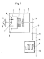
- a planetary gear 2, a friction clutch 3 (hereinafter referred to only as clutch 3) and a vibration damper 4 are accommodated in a gear housing 1.
- the drive takes place from a turbine shaft 5 of an exhaust gas turbine 6 onto the sun gear 7 of the planetary gear 2 designed as a stationary gear, which rotates a ring gear 9 and the clutch 3 connected to it via planet gears 8.
- the clutch 3, which will be discussed in more detail, connects or disconnects the turbine to and from the crankshaft 15 of an internal combustion engine 10. Between the output part of the clutch 3 and the engine 10, gearwheels 11, 12, 13, 14 are arranged for speed adjustment which are stored in their own housing, not shown. Immediately after the clutch 3, the vibration damper 4 is provided on the output side.
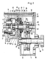
- Fig. 2 Details of the clutch 3 and the transmission are shown in Fig. 2, where corresponding parts have the same numbers as in Fig. 1.
- the ring gear 9 of the planetary gear 2 is via a ring gear carrier 19, with which it is firmly and pressure-tight, on a Shaft 20 mounted, which is mounted in the gear housing 1 and in the planet carrier 18.
- the planet carrier 18 is screwed onto the housing 16 of the exhaust gas turbine 6 for structural reasons, but it could also be attached directly to the gear housing 1, to which the housing 16 is connected by means of screws 17.
- the ring gear 9 with the ring gear carrier 19 together form a cylinder 21 in which an annular piston 22 is displaceably but pressure-tightly guided.
- a snap ring 23 in the cylinder limits the path by which the annular piston 22 can be displaced.
- An annular extension on the annular piston 22 is provided with cutouts 24 for receiving the drivers of so-called outer plates 25 Mistake.
- the latter cooperate with so-called inner fins 26 which engage with an internal toothing in a corresponding profile in a sleeve-shaped extension 27 of the gear 11.
- the plate pack thus formed is supported on the side facing away from the annular piston 22 by a pressure plate 28. This is loaded by disc springs 29 in the sense of engaging.
- the plate springs 29 are supported on the gear 11 and press the pressure plate 28 against a snap ring 30 which is arranged such that the lamellae are not pressed together by it or by the plate springs 29 when the clutch is open.
- a fluid is continuously supplied to an annular chamber 31 formed by the cylinder 21 and the annular piston 22 by an external pump, not shown.
- this is lubricating oil from the engine 10, which is conveyed from the lubricating oil pump of the engine to the transmission housing 1 via lines, not shown.
- bores 32, 33 are provided in the housing 1, through which the oil leads to a bore 34 in the shaft 20 and from there through radial bores 35 in the shaft 20, 36 in a sleeve 37 and 38 in the cylinder 21 and through an end slot 39 arrives in the annular piston 22 in the annular chamber 31.
- a pressure builds up in the annular chamber 31 depending on the speed of the turbine by rotating the cylinder filled with the lubricating oil as a fluid, which increases quadratically with the speed until the retaining force of the plate springs 29 is exceeded and so that the plate pack 25, 26 is pressed together.
- the torque output by the turbine is thus transmitted to the crankshaft of the engine 10 via the gearwheels 11, 12, 13, 14.
- the torque that can be transmitted depends on the number of friction surfaces, the coefficient of friction of the plates and the contact pressure of the piston, which as a variable depends on the speed of the turbine.
- the transmissible torque resulting from these three values must always be greater than the torque given off by the turbine, but torque peaks coming from the engine side must not lead to the turbine being overloaded. This is particularly true at maximum turbine speed, where the torque to be transmitted by the clutch reaches its maximum value.
- the contact pressure of the piston 22 is limited by the prestressed disk springs 29, which also When the preload force is reached by the piston 22, dodge accordingly until the piston comes into contact with the snap ring 30.
- the prestressing force now prevailing can no longer be exceeded, a further increase in the pressure in the annular chamber 31 would cause the slats 25, 26 to slip.
- bolts 42 are fastened in a pressure-tight manner in the ring gear carrier 19, which protrude into corresponding recesses in the annular piston 22 and prevent the latter from rotating undesirably relative to the cylinder 21.
- these recesses 43 have the shape of concentrically curved to the axis of rotation over an angle ⁇ extending grooves (Fig. 3).
- the bolts 42 are in normal operation, i.e. when the turbine 6 is driving, at the right end of the grooves 43 in relation to FIG. 3. If, for whatever reason, the speed of the motor suddenly increases so much that the output side of the clutch 3, i.e.
- the grooves 43 are covered towards the annular chamber 31. This can be done with one disk 44 in front of each groove or with a single annular disk covering all grooves 43.
- the washers 44 or the washer are pressed with springs 45 against the ring piston, so that the oil in the grooves 43 has to be squeezed out, as it were, by the bolts 42 against the spring-loaded washers, thus achieving the desired damping effect.
- the springs 45 are adjusted in their contact force so that they not only press the disks 44 against the annular piston 22, but also bring the plates 25, 26 to the mutual contact via the annular piston 22 even when the clutch is open.
- the clutch still has so much slip that the relative rotation of the ring piston is not hindered.
- the springs 45 therefore only exert a so-called initial force to facilitate the coupling process.
- a second relief bore 48 is provided in the cylinder 21, which connects the annular chamber in the area of its largest diameter to the gearbox interior 41 and has a very small cross section has, that is, substantially smaller than the relief bores 40. Otherwise, no pressure could build up in the annular chamber 31 even in normal operation.
- the gears 11, 12 are still accommodated in the transmission housing 1.
- the gear 12 is rotatably mounted on an output shaft 49 and connected to the output shaft 49 via the vibration damper 4.
- the gear 13, which meshes with the gear 14 (not shown here), is placed on the free end of the output shaft 49 protruding from the gear housing 1.
- a flange could also be fitted for connection to the crankshaft 15 or to an additional gear with the gearwheels 13, 14.
- the vibration damper 4 is arranged approximately in the manner of the gear 11 in FIG. 2 on the shaft 20.
- the vibration damper 4 has the task of keeping the rotational irregularities emanating from the engine, which can be very high especially in the lower speed range, as far as possible from the clutch and thus also from the turbine 6. Despite its possibly separate arrangement, the vibration damper 4 forms an essential part of the clutch. This also applies if the vibration damper is arranged at another location, not mentioned here, between the crankshaft 15 of the engine 10 and the actual clutch 3.
- the oil entering the transmission interior 41 through the relief bores 40, 48 and at other points can flow back to the engine 10 through a bore 50 in the transmission housing 1 directly or via lines, not shown.
Landscapes
- Engineering & Computer Science (AREA)
- General Engineering & Computer Science (AREA)
- Physics & Mathematics (AREA)
- Fluid Mechanics (AREA)
- Mechanical Engineering (AREA)
- Hydraulic Clutches, Magnetic Clutches, Fluid Clutches, And Fluid Joints (AREA)
- Combined Controls Of Internal Combustion Engines (AREA)
- Mechanical Operated Clutches (AREA)
Abstract
Description
- Die Erfindung betrifft eine Reibungskupplung gemäß dem Oberbegriff des Hauptanspruchs. Derartige Turbinen sollen bei Nutzfahrzeugen wie Lkw's u.ä. zum Einsatz kommen um Kraftstoff zu sparen.
- Druckmittelbetätigte Reibungskupplungen, wie sie in verschiedenen Ausführungen bekannt sind, sind für den genannten Zweck nicht brauchbar, da die Ein- und Ausschaltvorgänge in Abhängigkeit von der Turbinen- und/oder Motordrehzahl selbständig erfolgen müssen, um zusätzliche Steuerungseinrichtungen zu vermeiden. Auch sind keine mechanisch schaltbare Reibungskupplungen bekannt, die den Anforderungen des Einsatzfalles genügen.
- Von daher liegt der Erfindung die Aufgabe zugrunde, eine Kupplung für den im Oberbegriff genannten Zweck zu schaffen.
- Die Aufgabe wird mit einer Reibungskupplung gelöst, die die Merkmale des Hauptanspruchs aufweist. In dem in Abhängigkeit von der Turbinendrehzahl umlaufenden Zylinder übt das zugeführte Fluid unter der Einwirkung der Fliehkraft einen Druck auf den Kolben aus, der die Reibkörper gegen die Kraft einer Feder zusammendrückt. Wenn die Turbinendrehzahl sinkt und der Druck des Fluids abnimmt, wird die Kupplung von der Feder wieder geöffnet.
- Eine zweckmäßige Ausführungsform wird im Anspruch 2 aufgezeigt. Die Verwendung des Motor-Schmieröls als Fluid für die Kupplung (Anspruch 3) bringt insofern einen wesentlichen Vorteil, daß kein zusätzlicher, in sich geschlossener Fluidkreislauf für die Kupplungsbetätigung erforderlich ist. Die ohnehin vorhandene Pumpe versorgt auch die Kupplung mit Öl. Da der Druck des zugeführten Motor-Schmieröls nicht konstant ist und der Zylinder nur ein begrenztes Volumen hat, in dem sich ein von der Turbinendrehzahl abhängiger Druck aufbauen soll, ist eine Entlastungsbohrung vorgesehen (Anspruch 4), über die alles nicht zum Druckaufbau benötigte Öl abgeführt wird bzw. über die ein evtl. zu hoher Schmieröl-Druck abgebaut wird.
Der Kolben wird zweckmäßigerweise gegen ungewolltes Verdrehen gesichert (Anspruch 5). Dabei kann eine begrenzte relative Verdrehung zwischen dem Kolben und dem Zylinder dazu benutzt werden, die Fluidzufuhr zu unterbrechen, wenn die Drehzahl auf der Abtriebsseite höher wird als die auf der Antriebsseite der Kupplung (Anspruch 6). Damit wird eine Überlastsicherung für die Turbine bei plötzlichem Drehzahlanstieg des Motors, z.B. beim Herunterschalten im Gefälle, geschaffen. Eine vorteilhafte Weiterbildung der Kupplung wird mit dem Anspruch 7 aufgezeigt: die federnde Abdeckung der Nut läßt das in der Nut befindliche Fluid bei der Relativverdrehung zwischen Kolben und Zylinder nur langsam entweichen, wodurch ein schlagartiges Öffnen und Schließen der Kupplung vermieden wird. - Eine Weiterbildung der Kupplung nach Anspruch 8 ist sinnvoll, um die Turbine bei Motor-Leerlauf vom Motor abzukuppeln, auch wenn sie schon oder noch Leistung bringt. Das ist insbesondere bei einer plötzlichen Drehzahlverringerung sinnvoll, z.B. wenn der Fahrer des Fahrzeugs vom Kupplungspedal abrutscht. Eine zweckmäßige Ausführung für eine Einrichtung zum Abkuppeln der Turbine vom Motor in solchen Fällen durch Unterbrechen der Fluidzufuhr wird mit dem Anspruch 9 aufgezeigt. Da eine 100%ige Abdichtung mit einfachen Mitteln nicht zu erreichen ist, ist eine weitere Entlastungsbohrung nach Anspruch 10 empfehlenswert. Da nur Lecköl abgeführt zu werden braucht und der Druckaufbau im Zylinder bei normaler Fluidzufuhr sichergestellt sein muß, soll diese Bohrung nur einen ganz geringen Querschnitt aufweisen.
- Zum Schutz der Kupplung vor vom Motor ausgehenden Schwingungen (Drehungleichförmigkeiten), die insbesondere im unteren Drehzahlbereich des Motors sehr hoch sind, ist ein Dämpfungsglied vorgesehen (Anspruch 11), das nach Anspruch 12 angeordnet werden kann. Das Dämpfungsglied (Schwingungsdämpfer) muß nicht in die Kupplung integriert sein, sondern kann auch getrennt von der Kupplung angeordnet werden, z.B. innerhalb einer Getriebestufe oder zwischen zwei Getriebestufen, die zwischen der Kupplung und der Kurbelwelle des Motors angeordnet ist bzw. sind.
- Um einen einwandfreien Beginn des Schließvorganges ohne Verzögerungen zu erzielen ist die weitere Ausgestaltung der Kupplung nach Anspruch 13 zweckmäßig, wofür im Anspruch 14 eine sehr einfache Ausführung aufgezeigt wird. Zur Begrenzung des maximal übertragbaren Drehmoments dient die Ausbildung der Kupplung nach Anspruch 15.
- Die Erfindung wird nachstehend anhand eines in vier Figuren dargestellten Ausführungsbeispiels beschrieben. Es zeigen
- Fig. 1 ein Schemabild von einem Getriebe, bei dem die erfindungsgemäße Kupplung eingesetzt ist,
- Fig. 2 einen Schnitt durch ein solches Getriebe mit geringfügig geändertem Aufbau,
- Fig. 3 einen Teilschnitt entlang der Linie A-A in Fig. 2, und
- Fig. 4 einen Teilschnitt entlang der Linie B-B in Fig. 2.
- In einem Getriebegehäuse 1 sind ein Planetengetriebe 2, eine Reibungskupplung 3 (im folgenden nur als Kupplung 3 bezeichnet) und ein Schwingungsdämpfer 4 untergebracht. Der Antrieb erfolgt von einer Turbinenwelle 5 einer Abgasnutzturbine 6 auf das Sonnenrad 7 des als Standgetriebe ausgeführten Planetengetriebes 2, das über Planetenräder 8 ein Hohlrad 9 und die mit ihm verbundene Kupplung 3 in Rotation versetzt. Die Kupplung 3, auf die noch näher eingegangen wird, verbindet bzw. trennt die Turbine mit bzw. von der Kurbelwelle 15 eines Verbrennungsmotors 10. Zwischen dem Abtriebsteil der Kupplung 3 und dem Motor 10 sind zur Drehzahlanpassung Zahnräder 11, 12,13,14 angeordnet, die in einem eigenen, nicht dargestellten Gehäuse gelagert sind. Unmittelbar nach der Kupplung 3 ist ausgangsseitig der Schwingungsdämpfer 4 vorgesehen.
- Einzelheiten der Kupplung 3 bzw. des Getriebes sind in Fig. 2 gezeigt, wo entsprechende Teile dieselben Nummern tragen wie in Fig. 1. Das Hohlrad 9 des Planetengetriebes 2 ist über einen Hohlradträger 19, mit dem es fest und druckdicht verbunden ist, auf einer Welle 20 gelagert, die im Getriebegehäuse 1 und im Planetenträger 18 gelagert ist. Der Planetenträger 18 ist aus konstruktiven Gründen am Gehäuse 16 der Abgasnutzturbine 6 angeschraubt, er könnte aber auch direkt am Getriebegehäuse 1 befestigt sein, mit dem das Gehäuse 16 mittels Schrauben 17 verbunden ist.
- Das Hohlrad 9 mit dem Hohlradträger 19 bilden zusammen einen Zylinder 21, in dem ein Ringkolben 22 verschiebbar, aber druckdicht geführt ist. Die Dichtelemente brauchen, da bekannt, nicht dargestellt und beschrieben zu werden. Ein Sprengring 23 im Zylinder begrenzt den Weg, um den der Ringkolben 22 verschiebbar ist. Ein ringförmiger Ansatz am Ringkolben 22 ist mit Aussparungen 24 zur Aufnahme der Mitnehmer von sogenannten Außenlamellen 25 versehen. Letztere wirken mit sogenannten Innenlamellen 26 zusammen, die mit einer Innenverzahnung in ein entsprechendes Profil in einem hülsenförmigen Ansatz 27 des Zahnrades 11 eingreifen. Das so gebildete Lamellenpaket wird auf der dem Ringkolben 22 abgewendeten Seite von einer Druckplatte 28 abgestützt. Diese ist von Tellerfedern 29 im Sinne des Einkuppelns belastet. Dabei stützen sich die Tellerfedern 29 am Zahnrad 11 ab und drücken die Druckplatte 28 gegen einen Sprengring 30, der so angeordnet ist, daß die Lamellen von ihm bzw. von den Tellerfedern 29 nicht zusammengedrückt werden, wenn die Kupplung geöffnet ist.
- Von einer externen, nicht gezeigten Pumpe wird einer vom Zylinder 21 und vom Ringkolben 22 gebildete Ringkammer 31 ständig ein Fluid zugeführt. Der Einfachheit halber handelt es sich dabei um Schmieröl vom Motor 10, das von der Schmierölpumpe des Motors über nicht gezeigte Leitungen zum Getriebegehäuse 1 gefördert wird. Im Gehäuse 1 sind dazu Bohrungen 32,33 vorgesehen durch die das Öl zu einer Bohrung 34 in der Welle 20 und von dort weiter durch radiale Bohrungen 35 in der Welle 20, 36 in einer Hülse 37 und 38 im Zylinder 21 sowie durch einen stirnseitigen Schlitz 39 im Ringkolben 22 in die Ringkammer 31 gelangt.
Durch eine gezielte Schmierölzufuhr und entsprechende Dimensionierung der Kolbenfläche baut sich in der Ringkammer 31 in Abhängigkeit von der Drehzahl der Turbine durch Rotieren des mit dem Schmieröl als Fluid gefüllten Zylinders ein Druck auf, der quadratisch zur Drehzahl ansteigt, bis die Rückhaltekraft der Tellerfedern 29 überschritten und damit das Lamellenpaket 25,26 zusammengepreßt wird. Das von der Turbine abgegebene Drehmoment wird so über die Zahnräder 11,12,13,14 auf die Kurbelwelle des Motors 10 übertragen. Das übertragbare Drehmoment ist abhängig von der Anzahl der Reibflächen, dem Reibwert der Lamellen und der Anpreßkraft des Kolbens, die als Variable abhängig von der Drehzahl der Turbine ist. - Das sich durch diese drei Werte ergebende übertragbare Drehmoment muß immer größer sein als das von der Turbine abgegebene Moment, wobei jedoch von der Motorseite kommende Drehmomentspitzen nicht zur Überlastung der Turbine führen dürfen. Das gilt in ganz besonderem Maße bei maximaler Turbinendrehzahl, wo das von der Kupplung zu übertragende Drehmoment seinen Maximalwert erreicht. Um auch in diesem Betriebspunkt das Verhältnis des von der Kupplung übertragbaren Drehmoments zu dem von der Turbine abgegebenen Drehmoment auf einen für das Gesamtaggregat, insbesondere aber für die Turbine unschädlichen Wert zu begrenzen, ist die Anpreßkraft des Kolbens 22 durch die vorgespannten Tellerfedern 29 begrenzt, die bei Erreichen der Vorspannkraft durch den Kolben 22 entsprechend ausweichen, bis der Kolben am Sprengring 30 zur Anlage kommt. Die jetzt herrschende Vorspannkraft kann nicht mehr überschritten werden, ein weiteres Ansteigen des Druckes in der Ringkammer 31 würde zum Durchrutschen der Lamellen 25,26 führen.
- Zum Druckaufbau in der Ringkammer 31 ist, abgesehen von Leckverlusten, nur eine dem Volumen der Ringkammer entsprechende Ölmenge notwendig. Da aber ständig Öl zugeführt wird, sind zum Abführen des überschüssigen Öles Entlastungsbohrungen 40 vorgesehen, die die Ringkammer 31 mit dem Getriebeinnenraum 41 verbinden. Für einen einwandfreien Druckaufbau in der Ringkammer ist es erforderlich, die Entlastungsbohrungen von einem Ort mit möglichst geringer Umfangsgeschwindigkeit ausgehen zu lassen, d.h. im Bereich des kleinsten Durchmessers der Ringkammer 31.
- Achsparallel zur Rotationsachse der Reibungskupplung 3 sind Bolzen 42 druckdicht im Hohlradträger 19 befestigt, die in entsprechende Ausnehmungen im Ringkolben 22 ragen und diesen an einem unerwünschten Verdrehen relativ zum Zylinder 21 hindern. Im dargestellten Ausführungsbeispiel haben diese Ausnehmungen 43 die Form von sich konzentrisch zur Rotationsachse gekrümmt über einen Winkel ß erstreckenden Nuten (Fig. 3). Die Bolzen 42 liegen im Normalbetrieb, d.h. bei treibender Turbine 6, am - bezogen auf Fig. 3 - rechten Ende der Nuten 43 an. Wenn, aus welchen Gründen auch immer, die Drehzahl des Motors plötzlich so weit ansteigt, daß die Abtriebsseite der Kupplung 3, also der Ringkolben 22, schneller dreht als die Antriebsseite, also der Zylinder 21, und diese überholt, dann ist das nur bis zum Anschlag der Bolzen 42 am - wieder bezogen auf Fig.3 - linken Ende der Nuten 43 möglich (gestrichelte Kontur in Fig. 3). In dieser Stellung ist die Ölzufuhr zur Ringkammer 31 zwischen den Bohrungen 38 im Zylinder 21 und dem Schlitz 39 im Ringkolben 22 unterbrochen mit der Folge, daß die Kupplung wegen ihrer Leckverluste öffnet und die Verbindung zwischen Turbine 6 und Motor 10 unterbricht.
- Um zu vermeiden, daß bei der Relativverdrehung des Ringkolbens der Wechsel von der einen in die andere Endlage schlagartig erfolgt, sind die Nuten 43 zur Ringkammer 31 hin abgedeckt. Dies kann mit je einer Scheibe 44 vor jeder Nut erfolgen oder mit einer einzigen ringförmigen, alle Nuten 43 abdeckenden Scheibe. Dabei werden die Scheiben 44 bzw. wird die Scheibe mit Federn 45 gegen den Ringkolben gedrückt, so daß das in den Nuten 43 befindliche Öl gewissermaßen von den Bolzen 42 gegen die angefederten Scheiben herausgequetscht werden muß, womit der erwünschte Dämpfungseffekt erzielt wird.
- Die Federn 45 sind in ihrer Anstellkraft so abgestimmt, daß sie nicht nur die Scheiben 44 gegen den Ringkolben 22 drücken, sondern darüber hinaus über den Ringkolben 22 die Lamellen 25,26 auch bei geöffneter Kupplung zur gegenseitigen Anlage bringen. Die Kupplung hat dabei aber immer noch so viel Schlupf, daß die Relativverdrehung des Ringkolbens nicht behindert ist. Die Federn 45 üben also nur eine sog. Initialkraft aus zum Erleichtern des Einkuppelvorganges.
- Um die Turbine im unteren Drehzahlbereich des Motors vom Motor abzukuppeln, insbesondere bei einer plötzlichen Drehzahlverringerung, ist für solche Fälle eine Unterbrechung der Ölzufuhr zur Kupplung vorgesehen. In der Welle 20 sind einander gegenüberliegend zwei Kolben 46 in einer radialen Durchgangsbohrung angeordnet, deren Stirnseiten unter dem Druck von Federn 47 (Fig. 4) aneinander anliegen und, da der Durchmesser der Kolben 46 größer ist als der der Bohrung 34, die Bohrung 34 verschließen. Dabei ragt jeder Kolben 46 bis zur Rotationsachse der Welle 20 in die Bohrung 34 hinein. Erst bei zunehmender Drehzahl der Welle 20 werden die Kolben 46 unter dem Einfluß der Fliehkraft gegen die Wirkung der Federn 47 radial nach außen gedrückt und geben so die Bohrung 34 bzw. den Öldurchfluß frei. Mit den stirnseitig anliegenden Kolben 46 ist eine 100%ige Abdichtung nicht gewährleistet. Um zu verhindern, daß das durch den Spalt durchtretende Öl in der Ringkammer 31 einen zum Einkuppeln ausreichenden Druck aufbaut, ist im Zylinder 21 eine zweite Entlastungsbohrung 48 vorgesehen, die die Ringkammer im Bereich ihres größten Durchmessers mit dem Getriebeinnenraum 41 verbindet und einen sehr kleinen Querschnitt besitzt, d.h. wesentlich kleiner als die Entlastungsbohrungen 40. Andernfalls könnte sich auch im Normalbetrieb kein Druck in der Ringkammer 31 aufbauen.
- Bei der in Fig. 2 dargestellten Variante des Ausführungsbeispiels sind die Zahnräder 11,12 noch im Getriebegehäuse 1 untergebracht. Dabei ist das Zahnrad 12 drehbar auf einer Abtriebswelle 49 gelagert und über den Schwingungsdämpfer 4 mit der Abtriebswelle 49 verbunden. Am freien, aus dem Getriebegehäuse 1 herausragenden Ende der Abtriebswelle 49 ist das Zahnrad 13 aufgesetzt, das mit dem hier nicht dargestellten Zahnrad 14 kämmt. Es könnte statt des Zahnrades 13 auch ein Flansch aufgesetzt sein zum Anschluß an die Kurbelwelle 15 oder an ein zusätzliches Getriebe mit den Zahnrädern 13,14. Bei der Variante nach Fig. 1 ist der Schwingungsdämpfer 4 etwa in der Art wie das Zahnrad 11 in Fig. 2 auf der Welle 20 angeordnet. In beiden Fällen hat der Schwingungsdämpfer 4 die Aufgabe, vom Motor ausgehende Drehungleichförmigkeiten, die besonders im unteren Drehzahlbereich sehr hoch sein können, von der Kupplung und damit auch von der Turbine 6 weitestgehend fernzuhalten. Trotz seiner ggf. separaten Anordnung bildet der Schwingungsdämpfer 4 einen wesentlichen Bestandteil der Kupplung. Das gilt auch dann, wenn der Schwingungsdämpfer an einer anderen, hier nicht genannten Stelle zwischen der Kurbelwelle 15 des Motors 10 und der eigentlichen Kupplung 3 angeordnet ist.
- Das durch die Entlastungsbohrungen 40,48 und an anderen Stellen in den Getriebeinnenraum 41 gelangende Öl kann durch eine Bohrung 50 im Getriebegehäuse 1 direkt oder über nicht dargestellte Leitungen zum Motor 10 zurückfließen.
-
- 1. Getriebegehäuse
- 2 Planetengetriebe
- 3 Reibungskupplung
- 4 Schwingungsdämpfer
- 5 Turbinenwelle
- 6 Abgasnutzturbine
- 7 Sonnenrad
- 8 Planetenrad
- 9 Hohlrad
- 10 Verbrennungsmotor
- 11 Zahnrad
- 12 Zahnrad
- 13 Zahnrad
- 14 Zahnrad
- 15 Kurbelwelle
- 16 Gehäuse von 6
- 17 Schraube
- 18 Planetenträger
- 19 Hohlradträger
- 20 Welle
- 21 Zylinder
- 22 Ringkolben
- 23 Sprengring
- 24 Aussparung
- 25 Außenlamelle
- 26 Innenlamelle
- 27 Ansatz von 11
- 28 Druckplatte
- 29 Tellerfeder
- 30 Sprengring
- 31 Ringkammer
- 32 Bohrung in 1
- 33 Bohrung in 1
- 34 Bohrung in 20
- 35 Bohrung in 20
- 36 Bohrung in 37
- 37 Hülse
- 38 Bohrung in 21
- 39 Schlitz in 22
- 40 Entlastungsbohrung
- 41 Getriebeinnenraum
- 42 Bolzen
- 43 Ausnehmung (Nut) in 22
- 44 Scheibe
- 45 Feder
- 46 Kolben
- 47 Feder
- 48 Entlastungsbohrung
- 49 Abtriebswelle
- 50 Bohrung
Claims (15)
Applications Claiming Priority (2)
| Application Number | Priority Date | Filing Date | Title |
|---|---|---|---|
| DE3832288 | 1988-09-22 | ||
| DE3832288A DE3832288A1 (de) | 1988-09-22 | 1988-09-22 | Reibungskupplung |
Publications (2)
| Publication Number | Publication Date |
|---|---|
| EP0361030A1 true EP0361030A1 (de) | 1990-04-04 |
| EP0361030B1 EP0361030B1 (de) | 1992-03-25 |
Family
ID=6363528
Family Applications (1)
| Application Number | Title | Priority Date | Filing Date |
|---|---|---|---|
| EP89114418A Expired - Lifetime EP0361030B1 (de) | 1988-09-22 | 1989-08-04 | Reibungskupplung |
Country Status (6)
| Country | Link |
|---|---|
| US (1) | US5012906A (de) |
| EP (1) | EP0361030B1 (de) |
| JP (1) | JPH02125113A (de) |
| BR (1) | BR8904778A (de) |
| DE (2) | DE3832288A1 (de) |
| ES (1) | ES2014212A4 (de) |
Families Citing this family (13)
| Publication number | Priority date | Publication date | Assignee | Title |
|---|---|---|---|---|
| SE519200C2 (sv) * | 2001-06-05 | 2003-01-28 | Volvo Aero Corp | Gasturbinanordning med ett arrangemang för drivning av en eller flera hjälpapparater |
| US6553764B1 (en) | 2001-12-19 | 2003-04-29 | Caterpillar Inc | Enhanced response turbocharger using flywheel storage |
| KR100482111B1 (ko) * | 2002-09-18 | 2005-04-13 | 현대자동차주식회사 | 클러치 조작력 제어 장치 |
| EP1692379A1 (de) * | 2003-04-21 | 2006-08-23 | Preusse India (P) Ltd | Durch kombiniertes getriebesystem angetriebener zentrifugalmotorlader für mehrgeschwindigkeitsbetrieb und kraftübertragungsverfahren |
| JP2004360487A (ja) * | 2003-06-02 | 2004-12-24 | Honda Motor Co Ltd | 遊星歯車機構を備えた過給機 |
| US7478629B2 (en) * | 2004-11-04 | 2009-01-20 | Del Valle Bravo Facundo | Axial flow supercharger and fluid compression machine |
| US7174714B2 (en) * | 2004-12-13 | 2007-02-13 | Caterpillar Inc | Electric turbocompound control system |
| US20080121218A1 (en) * | 2004-12-13 | 2008-05-29 | Caterpillar Inc. | Electric turbocompound control system |
| DE102005004058B3 (de) * | 2005-01-28 | 2006-05-24 | Voith Turbo Gmbh & Co. Kg | Turbo-Compound-System |
| FR2994457B1 (fr) * | 2012-08-13 | 2014-08-08 | Valeo Systemes De Controle Moteur | Systeme d'entrainement d'au moins un compresseur, notamment d'un compresseur de suralimentation d'un moteur thermique |
| EP3063384A4 (de) * | 2013-10-28 | 2017-08-09 | Eaton Corporation | Verstärkersystem mit turbo und hybridantriebslader |
| US9862262B2 (en) | 2015-07-30 | 2018-01-09 | Ford Global Technologies, Llc | Hybrid vehicle powertrain |
| FR3137949B1 (fr) * | 2022-07-13 | 2024-08-16 | Safran Aircraft Engines | Système de changement de vitesse pour boîtier de relais d’accessoires de turbomachine d’aéronef et procédé d’utilisation |
Citations (4)
| Publication number | Priority date | Publication date | Assignee | Title |
|---|---|---|---|---|
| DE563327C (de) * | 1928-11-08 | 1932-11-03 | Pierre Marie Fromaget | Reibungskupplung fuer Kraftfahrzeuge |
| US3862676A (en) * | 1974-02-28 | 1975-01-28 | Dana Corp | Clutch controlled by engine speed and torque |
| EP0045867A1 (de) * | 1980-08-08 | 1982-02-17 | Knorr-Bremse Ag | Regeleinrichtung für einen Kompressor zum Betrieb in Kraftfahrzeugen |
| US4688665A (en) * | 1986-05-01 | 1987-08-25 | Caterpillar Inc. | Apparatus for preventing engine stall |
Family Cites Families (13)
| Publication number | Priority date | Publication date | Assignee | Title |
|---|---|---|---|---|
| US2702619A (en) * | 1955-02-22 | Overload slip clutch | ||
| US2197179A (en) * | 1939-02-03 | 1940-04-16 | United Aircraft Corp | Two-speed supercharger |
| US2402725A (en) * | 1942-05-22 | 1946-06-25 | Birkigt Louis | Internal-combustion engine |
| US2585968A (en) * | 1944-02-21 | 1952-02-19 | Schneider Brothers Company | Turbosupercharged internal-combustion engine having hydraulic means to connect turbine to engine output shaft at high load |
| US2642971A (en) * | 1947-11-12 | 1953-06-23 | Goodman Mfg Co | Overload released fluid clutch |
| US2646150A (en) * | 1948-09-28 | 1953-07-21 | Hobbs Transmission Ltd | Torque and speed responsive fluid clutch |
| US2803942A (en) * | 1953-01-13 | 1957-08-27 | Goetaverken Ab | Two-stroke-cycle internal combustion engines with scavenging and charging compressors driven by exhaust gas turbines |
| US3182777A (en) * | 1963-04-15 | 1965-05-11 | Deere & Co | Torque-limiting drive |
| US3487901A (en) * | 1967-12-11 | 1970-01-06 | Ingersoll Rand Co | Clutch |
| US3557635A (en) * | 1968-11-06 | 1971-01-26 | Gen Motors Corp | Transmission with phasing clutch for torque converter rotor |
| US4145888A (en) * | 1977-06-20 | 1979-03-27 | Borg-Warner Corporation | Combined turbocharger and accessory drive |
| US4238020A (en) * | 1977-12-08 | 1980-12-09 | Caterpillar Tractor Co. | Centrifugal clutch with an overspeed relief valve and clutch modulation |
| JPH0749811B2 (ja) * | 1985-04-02 | 1995-05-31 | 本田技研工業株式会社 | 遠心クラッチ |
-
1988
- 1988-09-22 DE DE3832288A patent/DE3832288A1/de active Granted
-
1989
- 1989-08-04 DE DE8989114418T patent/DE58901032D1/de not_active Expired - Fee Related
- 1989-08-04 ES ES89114418T patent/ES2014212A4/es active Pending
- 1989-08-04 EP EP89114418A patent/EP0361030B1/de not_active Expired - Lifetime
- 1989-09-20 JP JP1242441A patent/JPH02125113A/ja active Pending
- 1989-09-21 BR BR898904778A patent/BR8904778A/pt not_active IP Right Cessation
- 1989-09-21 US US07/410,593 patent/US5012906A/en not_active Expired - Fee Related
Patent Citations (4)
| Publication number | Priority date | Publication date | Assignee | Title |
|---|---|---|---|---|
| DE563327C (de) * | 1928-11-08 | 1932-11-03 | Pierre Marie Fromaget | Reibungskupplung fuer Kraftfahrzeuge |
| US3862676A (en) * | 1974-02-28 | 1975-01-28 | Dana Corp | Clutch controlled by engine speed and torque |
| EP0045867A1 (de) * | 1980-08-08 | 1982-02-17 | Knorr-Bremse Ag | Regeleinrichtung für einen Kompressor zum Betrieb in Kraftfahrzeugen |
| US4688665A (en) * | 1986-05-01 | 1987-08-25 | Caterpillar Inc. | Apparatus for preventing engine stall |
Also Published As
| Publication number | Publication date |
|---|---|
| EP0361030B1 (de) | 1992-03-25 |
| DE3832288A1 (de) | 1990-04-05 |
| ES2014212A4 (es) | 1990-07-01 |
| US5012906A (en) | 1991-05-07 |
| DE58901032D1 (de) | 1992-04-30 |
| BR8904778A (pt) | 1990-05-01 |
| DE3832288C2 (de) | 1992-02-13 |
| JPH02125113A (ja) | 1990-05-14 |
Similar Documents
| Publication | Publication Date | Title |
|---|---|---|
| DE19919449B4 (de) | Triebscheibe | |
| DE60011964T2 (de) | Automatisches Getriebe mit zweistufiger Reibungsvorrichtung | |
| EP1548313B2 (de) | Drehmomentübertragungseinrichtung | |
| DE19742586C2 (de) | Getriebe für eine Hilfsvorrichtung | |
| DE3832288C2 (de) | ||
| DE69707632T2 (de) | Zapfwellenantrieb mit selektiv betätigter Bremse | |
| EP4536987B1 (de) | Trockene doppelkupplung mit individuell betätigbaren teilkupplungen | |
| DE102008020683B4 (de) | Drehmomentwandler mit Anordnung für Kühlfluidströmung und Anordnung zur Drehmomentübertragung auf einen Dämpfer | |
| EP2012044B1 (de) | Mechanischer Torsionsschwingungsdämpfer | |
| DE102008063662A1 (de) | Lamelle für eine reibschlüssig arbeitende Einrichtung und reibschlüssig arbeitende Einrichtung mit einer solchen Lamelle | |
| DE69031689T2 (de) | Stufenlos verstellbares Getriebe | |
| DE19822426A1 (de) | Antriebsvorrichtung für Nebenaggregate einer Hubkolbenbrennkraftmaschine | |
| EP2126391B1 (de) | Federdruck-lamellenkupplung für kompressoren | |
| EP2503188A1 (de) | Schaltzylinder für eine Antriebseinrichtung, insbesondere für eine selbstfahrende Arbeitsmaschine, Antriebseinrichtung, Arbeitsmaschine sowie Verfahren zum Betreiben einer Arbeitsmaschine | |
| DE19836775A1 (de) | Drehmomentwandler und Verfahren zu dessen Herstellung | |
| DE3841237C2 (de) | Flügelzellenpumpen-Getriebekupplung für vierradgetriebene Fahrzeuge | |
| DE69403321T2 (de) | Getriebe mit progressiven anlauf, insbesondere für ein fahrzeug | |
| EP0797022B1 (de) | Torsionsschwingungsdämpfer | |
| DE10114281B4 (de) | Mehrfach-Kupplungseinrichtung und Radiallagerungskonzept hierfür | |
| DE3622335C2 (de) | Antriebseinrichtung für Nebenaggregate einer Brennkraftmaschine | |
| DE102014200331B4 (de) | Ölpumpenantrieb mit schaltbarer Antriebsübersetzung | |
| DE102007004990A1 (de) | Kupplungsvorrichtung | |
| DE4434324A1 (de) | Antriebseinheit für Nebenaggregate von Kraftfahrzeugen, sowie Antrieb von Nebenaggregaten durch Wellen unterschiedlicher Drehzahl | |
| DE68903075T2 (de) | Regelbares getriebe. | |
| DE69220023T2 (de) | Zahnradgetriebe mit Kupplungen und Bremsen, die durch ein wellenförmiges Profil gehalten werden |
Legal Events
| Date | Code | Title | Description |
|---|---|---|---|
| PUAI | Public reference made under article 153(3) epc to a published international application that has entered the european phase |
Free format text: ORIGINAL CODE: 0009012 |
|
| AK | Designated contracting states |
Kind code of ref document: A1 Designated state(s): DE ES FR GB IT NL SE |
|
| 17P | Request for examination filed |
Effective date: 19900301 |
|
| ITCL | It: translation for ep claims filed |
Representative=s name: BARZANO' E ZANARDO ROMA S.P.A. |
|
| TCNL | Nl: translation of patent claims filed | ||
| EL | Fr: translation of claims filed | ||
| 17Q | First examination report despatched |
Effective date: 19901128 |
|
| RAP1 | Party data changed (applicant data changed or rights of an application transferred) |
Owner name: HURTH GETRIEBE UND ZAHNRAEDER G.M.B.H. |
|
| GRAA | (expected) grant |
Free format text: ORIGINAL CODE: 0009210 |
|
| AK | Designated contracting states |
Kind code of ref document: B1 Designated state(s): DE ES FR GB IT NL SE |
|
| REF | Corresponds to: |
Ref document number: 58901032 Country of ref document: DE Date of ref document: 19920430 |
|
| ET | Fr: translation filed | ||
| ITF | It: translation for a ep patent filed | ||
| PG25 | Lapsed in a contracting state [announced via postgrant information from national office to epo] |
Ref country code: ES Free format text: LAPSE BECAUSE OF FAILURE TO SUBMIT A TRANSLATION OF THE DESCRIPTION OR TO PAY THE FEE WITHIN THE PRESCRIBED TIME-LIMIT Effective date: 19920706 |
|
| GBT | Gb: translation of ep patent filed (gb section 77(6)(a)/1977) | ||
| PGFP | Annual fee paid to national office [announced via postgrant information from national office to epo] |
Ref country code: SE Payment date: 19920818 Year of fee payment: 4 |
|
| PGFP | Annual fee paid to national office [announced via postgrant information from national office to epo] |
Ref country code: FR Payment date: 19920827 Year of fee payment: 4 |
|
| PGFP | Annual fee paid to national office [announced via postgrant information from national office to epo] |
Ref country code: NL Payment date: 19920831 Year of fee payment: 4 |
|
| PLBE | No opposition filed within time limit |
Free format text: ORIGINAL CODE: 0009261 |
|
| STAA | Information on the status of an ep patent application or granted ep patent |
Free format text: STATUS: NO OPPOSITION FILED WITHIN TIME LIMIT |
|
| PGFP | Annual fee paid to national office [announced via postgrant information from national office to epo] |
Ref country code: DE Payment date: 19930215 Year of fee payment: 4 |
|
| 26N | No opposition filed | ||
| PG25 | Lapsed in a contracting state [announced via postgrant information from national office to epo] |
Ref country code: GB Effective date: 19930804 |
|
| PG25 | Lapsed in a contracting state [announced via postgrant information from national office to epo] |
Ref country code: SE Effective date: 19930805 |
|
| PG25 | Lapsed in a contracting state [announced via postgrant information from national office to epo] |
Ref country code: NL Effective date: 19940301 |
|
| GBPC | Gb: european patent ceased through non-payment of renewal fee |
Effective date: 19930804 |
|
| NLV4 | Nl: lapsed or anulled due to non-payment of the annual fee | ||
| PG25 | Lapsed in a contracting state [announced via postgrant information from national office to epo] |
Ref country code: FR Effective date: 19940429 |
|
| PG25 | Lapsed in a contracting state [announced via postgrant information from national office to epo] |
Ref country code: DE Effective date: 19940503 |
|
| REG | Reference to a national code |
Ref country code: FR Ref legal event code: ST |
|
| EUG | Se: european patent has lapsed |
Ref document number: 89114418.0 Effective date: 19940310 |
|
| PG25 | Lapsed in a contracting state [announced via postgrant information from national office to epo] |
Ref country code: IT Free format text: LAPSE BECAUSE OF NON-PAYMENT OF DUE FEES;WARNING: LAPSES OF ITALIAN PATENTS WITH EFFECTIVE DATE BEFORE 2007 MAY HAVE OCCURRED AT ANY TIME BEFORE 2007. THE CORRECT EFFECTIVE DATE MAY BE DIFFERENT FROM THE ONE RECORDED. Effective date: 20050804 |