EP0361049B1 - Toupie - Google Patents
Toupie Download PDFInfo
- Publication number
- EP0361049B1 EP0361049B1 EP89114972A EP89114972A EP0361049B1 EP 0361049 B1 EP0361049 B1 EP 0361049B1 EP 89114972 A EP89114972 A EP 89114972A EP 89114972 A EP89114972 A EP 89114972A EP 0361049 B1 EP0361049 B1 EP 0361049B1
- Authority
- EP
- European Patent Office
- Prior art keywords
- bearing
- axis
- standing axis
- opening
- ball
- Prior art date
- Legal status (The legal status is an assumption and is not a legal conclusion. Google has not performed a legal analysis and makes no representation as to the accuracy of the status listed.)
- Expired - Lifetime
Links
- 229920003023 plastic Polymers 0.000 claims description 8
- 239000004033 plastic Substances 0.000 claims description 8
- 230000000717 retained effect Effects 0.000 claims 3
- 238000009987 spinning Methods 0.000 description 7
- 239000002184 metal Substances 0.000 description 6
- 238000010276 construction Methods 0.000 description 4
- 238000004519 manufacturing process Methods 0.000 description 4
- NJPPVKZQTLUDBO-UHFFFAOYSA-N novaluron Chemical compound C1=C(Cl)C(OC(F)(F)C(OC(F)(F)F)F)=CC=C1NC(=O)NC(=O)C1=C(F)C=CC=C1F NJPPVKZQTLUDBO-UHFFFAOYSA-N 0.000 description 4
- 238000003780 insertion Methods 0.000 description 3
- 230000037431 insertion Effects 0.000 description 3
- 238000004026 adhesive bonding Methods 0.000 description 2
- 230000006378 damage Effects 0.000 description 2
- 238000003860 storage Methods 0.000 description 2
- 238000003466 welding Methods 0.000 description 2
- 208000034656 Contusions Diseases 0.000 description 1
- 208000027418 Wounds and injury Diseases 0.000 description 1
- 230000000295 complement effect Effects 0.000 description 1
- 238000002788 crimping Methods 0.000 description 1
- 238000001746 injection moulding Methods 0.000 description 1
- 208000014674 injury Diseases 0.000 description 1
- 238000009434 installation Methods 0.000 description 1
- 230000008018 melting Effects 0.000 description 1
- 238000002844 melting Methods 0.000 description 1
- 230000002093 peripheral effect Effects 0.000 description 1
- 239000000243 solution Substances 0.000 description 1
- 238000002604 ultrasonography Methods 0.000 description 1
Images
Classifications
-
- A—HUMAN NECESSITIES
- A63—SPORTS; GAMES; AMUSEMENTS
- A63H—TOYS, e.g. TOPS, DOLLS, HOOPS OR BUILDING BLOCKS
- A63H1/00—Tops
Definitions
- the invention relates to a toy spinning top with the features specified in the preamble of claim 1.
- Toy spinning tops generally have a base in which a vertical, fixed base axis is held with its lower end.
- the connection between the pedestal and the pedestal is to be designed to be deductible, on the one hand to prevent the gyroscope from being actuated on the relatively sharp-edged end of its pedestal and thus causing damage to floors or furniture.
- the exposed end of the standing axis would pose a considerable risk of injury to the children handling such a damaged spinning top.
- the actual gyroscope body is rotatably mounted on the fixed standing axis.
- this mounting must ensure that the gyro rotation axis is held in a sufficiently precise vertical position and that the gyro body is effectively supported against its weight and the driving force acting downwards through the action of the swirl rod.
- two radial and one axial plain bearing are available between the standing axis and the gyro body.
- a first radial slide bearing is formed by a central, bush-like bearing opening in the tip part of the rotary body, which is preferably made of an injection-moldable or pourable plastic.
- the standing axis extends vertically upwards through this bearing opening.
- the second radial plain bearing is supported by another centric, Bush-like bearing opening in an insert part fastened in the tip part, likewise preferably made of an injection-moldable or pourable plastic.
- the upper end of the standing axis lies in this bearing opening.
- the vertical spacing of the two radial plain bearings ensures that the gyro rotation axis is kept vertical. Since relatively small transverse forces occur between the standing axis and the tip or insert part and the standing axis is held in the bearing openings with corresponding play, the sliding friction forces in these bearings are negligibly small.
- a crimp is provided between the tip part and the insert part, which serves as a vertical counter bearing for two ring disks threaded onto the standing axis from above.
- the insert part fastened in the tip part for example by ultrasound welding or gluing, is supported on these ring disks, as a result of which the axial bearing is provided.
- the lower ring disc can stand still due to crushing, while the upper one can rotate with the insert part and consequently the tip part.
- the plain bearing therefore takes place between the two metal ring disks and accordingly has a low sliding friction resistance and wear on.
- the said crimping also serves as a trigger protection for the gyro body from the standing axis.
- a disadvantage of this known construction is its extremely high installation effort.
- the two washers must be threaded onto the stand axis.
- assembly of the gyroscope on production machines is difficult because of the difficult handling of the washers.
- the object of the invention is to simplify and improve the bearing construction of the gyro body on the standing axis with regard to the manufacturing effort and, in particular, to enable automatic production.
- the axial bearing which has been regularly pursued in the prior art, is completely abandoned by crushing on the standing axis and bearing ring washers sitting thereon and is replaced by a design of the metal bearing elements in the manner of, for example, a tip bearing.
- One bearing element is itself formed by the upper end face of the standing axis.
- the other bearing element is realized by a bearing ball arranged on this end face, which sits at the closed inner end of the blind hole-like bearing opening of the insert part which is slipped over the upper end of the standing axis.
- the subject matter of the invention designed in this way can also be easily assembled by a production machine, since only the ball is inserted into the blind hole-like bearing opening of the prefabricated insert, then the stand axis is inserted and the arrangement thus created is inserted into the tip part. In a final step, the stand can be pushed onto the lower end of the stand axis.
- Another advantage lies in the reduced sliding friction between the bearing ball and the standing axis compared to the prior art, since there is an essentially point-like metal-metal contact.
- the assembly of the toy top according to the invention is further simplified.
- the insert part with the bearing ball already inserted can be provided as a pre-assembled part for final assembly of the gyro.
- the mounting of the bearing ball can be done by gluing, melting or - as indicated in the characterizing part of claim 3 - self-locking with a press fit.
- the bearing ball can, for example, be introduced into the bearing opening simultaneously with the injection molding or pouring of the insert part.
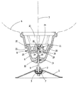
- the gyroscope has a base (1) designed as a flat-conical plastic molded part, in the tip of which an insertion opening (2) for the lower end (3) of the base axis (4) is formed.
- this insertion opening (2) the coaxial to the axis of rotation (5) of the actual (indicated by dashed lines) gyro body (6) standing axis (4) by means of the hat-like spring washer (7) is held trigger-proof and rotation-proof.
- the foot construction shown is the subject of European Patent No. 197092 (EP patent application 85 904 058.7).
- the gyroscope body (6) is rotatably mounted on the standing axis (4).
- it has at its lower end the multi-part bearing structure (8) which is essentially formed by the approximately frustoconical tip part (9) facing the base (1) and the insert part (11) sitting in its hollow interior (10).
- the standing axis (4) passes through the tip part (9) made of a sprayable plastic vertically upwards via a central, bush-like bearing opening (12). This forms a first radial slide bearing (13). With its upper end (23), the standing axis (4) lies in a central, bush-like bearing opening (14) in the insert part (11), which is designed in the manner of a blind hole and forms a second radial sliding bearing (15) for the axial sliding bearing Spinning top (6)
- a bearing ball (17) is held on the standing axis (4) at the closed inner end (16) of the bearing opening (14) with a press fit - that is to say self-locking - which is in a point-like metal-metal contact on the upper end face (18) of the standing axis ( 4) sits and thus forms an axial plain bearing (24) for the gyro body.
- the insert part (11) has in its jacket area an annular oblique flank (19) and a radial annular projection (20) arranged circumferentially on its peripheral edge on the circumferential body side.
- the insert part (11) is permanently connected to the tip part (9) by ultrasonic welding in these areas.
- the gyro body (6) is thus supported downwards via the axial slide bearing (24) formed by the bearing ball (17) and the end face (18) of the standing axis (4).
- a particularly intimate connection between the insert part (11) and the tip part (9) is achieved by the positive engagement of the inclined flank (19) and the ring projection (20) on the inner lateral surface of the tip part (9) and its complementary to the ring projection (20), circumferential ring shoulder (21) achieved.
- a crimp (22) is attached to the standing axis (4), which protects the tip part (9) and thus the gyroscope body (6) from being pulled off the standing axis (4) .
Landscapes
- Toys (AREA)
Claims (5)
- Toupie comportant- un pied (1),- un axe (4) fixe vertical retenu par son extrémité inférieure (3) dans ledit pied et- un corps de toupie (6) logé à pivotement sur cet axe, ledit axe (4)caractérisée en ce que-- traversant verticalement vers le haut à travers une ouverture de palier (12) centrale en forme de douille la pointe (9) du corps de toupie (6) réalisée de préférence en matière plastique injectée ou coulée, ladite ouverture formant un premier palier de glissement radial (13) pour le corps de toupie (6),-- reposant par son extrémité supérieure (23) dans une autre ouverture de palier (14) centrale en forme de douille, dans un insert (11) réalisé de préférence en matière plastique injectée ou coulée, et fixé dans la pointe (9), ladite ouverture formant un second palier de glissement radial (15) pour le corps de toupie (6) et-- comportant entre lui-même et l'insert (11) un palier de glissement axial (24) composé d'éléments de palier en métal qui soutient le corps de toupie (6) contre son propre poids et la force motrice agissant vers le bas par l'action de la tige de giration,
les éléments de palier en métal pour le palier de glissement axial (24) sont formés d'une part par la face supérieure (18) de l'axe (4) proprement dit et d'autre part par une bille de palier (17) disposée sur cette face (18), la bille étant logée sur l'extrémité intérieure (16) fermée de l'ouverture de palier (14) en forme de trou borgne de l'insert (11), enfoncée sur l'extrémité supérieure (23) de l'axe (4). - Toupie selon la revendication 1,
caractérisée en ce que
la bille de palier (17) est retenue à l'extrémité intérieure (16) fermée de l'ouverture de palier (14). - Toupie selon la revendication 2,
caractérisée en ce que
la bille de palier (17) est retenue par ajustage serré autoblocant dans l'ouverture de palier (14) en forme de trou borgne. - Toupie selon l'une des revendications précédentes,
caractérisée en ce que
la bille de palier (17) est trempée. - Toupie selon l'une des revendications précédentes,
caractérisée en ce que
la face supérieure (18) de l'axe (4) est trempée.
Applications Claiming Priority (2)
| Application Number | Priority Date | Filing Date | Title |
|---|---|---|---|
| DE8812179U | 1988-09-27 | ||
| DE8812179U DE8812179U1 (de) | 1988-09-27 | 1988-09-27 | Spielzeugkreisel |
Publications (3)
| Publication Number | Publication Date |
|---|---|
| EP0361049A2 EP0361049A2 (fr) | 1990-04-04 |
| EP0361049A3 EP0361049A3 (fr) | 1991-07-03 |
| EP0361049B1 true EP0361049B1 (fr) | 1993-12-15 |
Family
ID=6828330
Family Applications (1)
| Application Number | Title | Priority Date | Filing Date |
|---|---|---|---|
| EP89114972A Expired - Lifetime EP0361049B1 (fr) | 1988-09-27 | 1989-08-12 | Toupie |
Country Status (2)
| Country | Link |
|---|---|
| EP (1) | EP0361049B1 (fr) |
| DE (2) | DE8812179U1 (fr) |
Families Citing this family (3)
| Publication number | Priority date | Publication date | Assignee | Title |
|---|---|---|---|---|
| DE3914971A1 (de) * | 1988-10-05 | 1990-07-05 | Gisbert Paech | Spielzeugkreisel zum anschnippen nach dem zentrifugal-traegheitsprinzip |
| JP6130963B1 (ja) * | 2016-11-02 | 2017-05-17 | 株式会社エポック社 | 絞出具、補助部材、装飾体形成玩具及び装飾体形成玩具セット |
| KR102672350B1 (ko) * | 2021-10-22 | 2024-06-04 | 주식회사 키메이커스 | 스마트 팽이 |
Family Cites Families (6)
| Publication number | Priority date | Publication date | Assignee | Title |
|---|---|---|---|---|
| US965465A (en) * | 1910-02-21 | 1910-07-26 | Wizard Patent Developing Company | Toy top. |
| US2255454A (en) * | 1939-07-19 | 1941-09-09 | Frank H C Rust | Spinning top |
| DE1822865U (de) * | 1957-08-17 | 1960-12-01 | Peter Balleis | Kreisel mit drillspindelaufziehvorrichtung. |
| GB1015000A (en) * | 1963-12-23 | 1965-12-31 | Alfred Eleonhard Paulsen | Toy |
| DE8430096U1 (de) * | 1984-10-12 | 1985-02-07 | Lorenz Bolz - GmbH & Co, 8502 Zirndorf | Spielzeugkreisel mit einem standfuss |
| DE8711361U1 (de) * | 1987-08-21 | 1988-03-03 | Lewitz, Reinwald, 3100 Celle | Raumschiff |
-
1988
- 1988-09-27 DE DE8812179U patent/DE8812179U1/de not_active Expired
-
1989
- 1989-08-12 DE DE89114972T patent/DE58906430D1/de not_active Expired - Fee Related
- 1989-08-12 EP EP89114972A patent/EP0361049B1/fr not_active Expired - Lifetime
Also Published As
| Publication number | Publication date |
|---|---|
| EP0361049A3 (fr) | 1991-07-03 |
| EP0361049A2 (fr) | 1990-04-04 |
| DE58906430D1 (de) | 1994-01-27 |
| DE8812179U1 (de) | 1988-11-17 |
Similar Documents
| Publication | Publication Date | Title |
|---|---|---|
| DE69206225T2 (de) | Erdungsstiftschraube. | |
| EP0764798A2 (fr) | Dispositif porte-satellites avec support axial | |
| DE69912330T2 (de) | Aus Radmutter und Kappe bestehende Einheit mit Isolierscheibe | |
| DE4213831A1 (de) | Gerollte lagerbuchse und zapfen- oder wellenverbindung mit einer solchen lagerbuchse | |
| WO2013017156A1 (fr) | Colonne de direction dotée d'un palier de direction et palier de direction de colonne de direction | |
| EP2436298A2 (fr) | Lave-vaisselle, notamment lave-vaisselle ménager | |
| EP0692642B1 (fr) | Rondelle et arrangement d'un anneau de retenue avec une rondelle sur un arbre | |
| DE8904871U1 (de) | Hängekugellager für ein Fahrzeug | |
| EP2195480B1 (fr) | Lave-linge | |
| DE102009031886A1 (de) | Spindellagerung für eine Ringspinnmaschine | |
| DE2906734A1 (de) | Laufrolle in zwillingsradanordnung | |
| DE1298454B (de) | Stossdaempfendes Lager fuer Uhrwerke | |
| EP0349722B1 (fr) | Palier axial à aiguilles | |
| EP0361049A2 (fr) | Toupie | |
| DE102004001701A1 (de) | Antriebseinheit für ein Flurförderzeug mit Drehschemellenkung | |
| DE4300204A1 (fr) | ||
| DE8900848U1 (de) | Transport- und Montagehülse | |
| DE102007023364A1 (de) | Riemenscheibe | |
| DE10134950B4 (de) | Schraubenwinde | |
| DE2248515C3 (de) | Lagerung für drehbare Uhrwerksteile | |
| DE2457682A1 (de) | Kupplungslager | |
| DE3325170C2 (fr) | ||
| EP0531824B1 (fr) | Support élastique pour la fixation | |
| EP1988311A2 (fr) | Palier et actionneur linéaire équipé d'un tel palier | |
| DE102019118980A1 (de) | Als Lenkrolle ausgebildete Laufrolle |
Legal Events
| Date | Code | Title | Description |
|---|---|---|---|
| PUAI | Public reference made under article 153(3) epc to a published international application that has entered the european phase |
Free format text: ORIGINAL CODE: 0009012 |
|
| AK | Designated contracting states |
Kind code of ref document: A2 Designated state(s): DE ES FR GB IT |
|
| PUAL | Search report despatched |
Free format text: ORIGINAL CODE: 0009013 |
|
| AK | Designated contracting states |
Kind code of ref document: A3 Designated state(s): DE ES FR GB IT |
|
| 17P | Request for examination filed |
Effective date: 19910813 |
|
| 17Q | First examination report despatched |
Effective date: 19920814 |
|
| GRAA | (expected) grant |
Free format text: ORIGINAL CODE: 0009210 |
|
| AK | Designated contracting states |
Kind code of ref document: B1 Designated state(s): DE ES FR GB IT |
|
| PG25 | Lapsed in a contracting state [announced via postgrant information from national office to epo] |
Ref country code: IT Free format text: LAPSE BECAUSE OF FAILURE TO SUBMIT A TRANSLATION OF THE DESCRIPTION OR TO PAY THE FEE WITHIN THE PRE;WARNING: LAPSES OF ITALIAN PATENTS WITH EFFECTIVE DATE BEFORE 2007 MAY HAVE OCCURRED AT ANY TIME BEFORE 2007. THE CORRECT EFFECTIVE DATE MAY BE DIFFERENT FROM THE ONE RECORDED.SCRIBED TIME-LIMIT Effective date: 19931215 Ref country code: FR Effective date: 19931215 Ref country code: ES Free format text: THE PATENT HAS BEEN ANNULLED BY A DECISION OF A NATIONAL AUTHORITY Effective date: 19931215 |
|
| REF | Corresponds to: |
Ref document number: 58906430 Country of ref document: DE Date of ref document: 19940127 |
|
| GBT | Gb: translation of ep patent filed (gb section 77(6)(a)/1977) |
Effective date: 19940314 |
|
| EN | Fr: translation not filed | ||
| PG25 | Lapsed in a contracting state [announced via postgrant information from national office to epo] |
Ref country code: GB Effective date: 19940812 |
|
| PLBE | No opposition filed within time limit |
Free format text: ORIGINAL CODE: 0009261 |
|
| STAA | Information on the status of an ep patent application or granted ep patent |
Free format text: STATUS: NO OPPOSITION FILED WITHIN TIME LIMIT |
|
| 26N | No opposition filed | ||
| GBPC | Gb: european patent ceased through non-payment of renewal fee |
Effective date: 19940812 |
|
| PGFP | Annual fee paid to national office [announced via postgrant information from national office to epo] |
Ref country code: DE Payment date: 19950623 Year of fee payment: 7 |
|
| PG25 | Lapsed in a contracting state [announced via postgrant information from national office to epo] |
Ref country code: DE Effective date: 19970501 |