EP0361074B1 - Flüssigkristall-Anzeigevorrichtung - Google Patents
Flüssigkristall-Anzeigevorrichtung Download PDFInfo
- Publication number
- EP0361074B1 EP0361074B1 EP89115483A EP89115483A EP0361074B1 EP 0361074 B1 EP0361074 B1 EP 0361074B1 EP 89115483 A EP89115483 A EP 89115483A EP 89115483 A EP89115483 A EP 89115483A EP 0361074 B1 EP0361074 B1 EP 0361074B1
- Authority
- EP
- European Patent Office
- Prior art keywords
- liquid crystal
- crystal display
- panel
- housing
- display device
- Prior art date
- Legal status (The legal status is an assumption and is not a legal conclusion. Google has not performed a legal analysis and makes no representation as to the accuracy of the status listed.)
- Expired - Lifetime
Links
- 239000004973 liquid crystal related substance Substances 0.000 title claims description 82
- 229910052751 metal Inorganic materials 0.000 claims description 9
- 239000002184 metal Substances 0.000 claims description 9
- 125000006850 spacer group Chemical group 0.000 claims description 6
- 229910052782 aluminium Inorganic materials 0.000 claims description 5
- XAGFODPZIPBFFR-UHFFFAOYSA-N aluminium Chemical compound [Al] XAGFODPZIPBFFR-UHFFFAOYSA-N 0.000 claims description 5
- 239000004033 plastic Substances 0.000 claims description 4
- 229920003023 plastic Polymers 0.000 claims description 4
- 239000004411 aluminium Substances 0.000 claims 1
- 239000011521 glass Substances 0.000 description 14
- 210000004027 cell Anatomy 0.000 description 10
- 238000001816 cooling Methods 0.000 description 8
- 239000000463 material Substances 0.000 description 6
- 239000002390 adhesive tape Substances 0.000 description 4
- XEEYBQQBJWHFJM-UHFFFAOYSA-N Iron Chemical compound [Fe] XEEYBQQBJWHFJM-UHFFFAOYSA-N 0.000 description 2
- HCHKCACWOHOZIP-UHFFFAOYSA-N Zinc Chemical compound [Zn] HCHKCACWOHOZIP-UHFFFAOYSA-N 0.000 description 2
- 230000001788 irregular Effects 0.000 description 2
- 238000000034 method Methods 0.000 description 2
- 230000000630 rising effect Effects 0.000 description 2
- 229910052725 zinc Inorganic materials 0.000 description 2
- 239000011701 zinc Substances 0.000 description 2
- NIXOWILDQLNWCW-UHFFFAOYSA-N acrylic acid group Chemical group C(C=C)(=O)O NIXOWILDQLNWCW-UHFFFAOYSA-N 0.000 description 1
- 239000003086 colorant Substances 0.000 description 1
- 239000013078 crystal Substances 0.000 description 1
- 210000002858 crystal cell Anatomy 0.000 description 1
- 230000002542 deteriorative effect Effects 0.000 description 1
- 230000005484 gravity Effects 0.000 description 1
- 229910052736 halogen Inorganic materials 0.000 description 1
- 238000001746 injection moulding Methods 0.000 description 1
- 229910052742 iron Inorganic materials 0.000 description 1
- 238000004519 manufacturing process Methods 0.000 description 1
- 230000008520 organization Effects 0.000 description 1
- 230000002093 peripheral effect Effects 0.000 description 1
- 229910001220 stainless steel Inorganic materials 0.000 description 1
- 239000010935 stainless steel Substances 0.000 description 1
- 239000000758 substrate Substances 0.000 description 1
- 229910052721 tungsten Inorganic materials 0.000 description 1
- 239000010937 tungsten Substances 0.000 description 1
- -1 tungsten halogen Chemical class 0.000 description 1
Images


Classifications
-
- G—PHYSICS
- G02—OPTICS
- G02F—OPTICAL DEVICES OR ARRANGEMENTS FOR THE CONTROL OF LIGHT BY MODIFICATION OF THE OPTICAL PROPERTIES OF THE MEDIA OF THE ELEMENTS INVOLVED THEREIN; NON-LINEAR OPTICS; FREQUENCY-CHANGING OF LIGHT; OPTICAL LOGIC ELEMENTS; OPTICAL ANALOGUE/DIGITAL CONVERTERS
- G02F1/00—Devices or arrangements for the control of the intensity, colour, phase, polarisation or direction of light arriving from an independent light source, e.g. switching, gating or modulating; Non-linear optics
- G02F1/01—Devices or arrangements for the control of the intensity, colour, phase, polarisation or direction of light arriving from an independent light source, e.g. switching, gating or modulating; Non-linear optics for the control of the intensity, phase, polarisation or colour
- G02F1/13—Devices or arrangements for the control of the intensity, colour, phase, polarisation or direction of light arriving from an independent light source, e.g. switching, gating or modulating; Non-linear optics for the control of the intensity, phase, polarisation or colour based on liquid crystals, e.g. single liquid crystal display cells
- G02F1/133—Constructional arrangements; Operation of liquid crystal cells; Circuit arrangements
- G02F1/1333—Constructional arrangements; Manufacturing methods
- G02F1/133382—Heating or cooling of liquid crystal cells other than for activation, e.g. circuits or arrangements for temperature control, stabilisation or uniform distribution over the cell
- G02F1/133385—Heating or cooling of liquid crystal cells other than for activation, e.g. circuits or arrangements for temperature control, stabilisation or uniform distribution over the cell with cooling means, e.g. fans
-
- G—PHYSICS
- G02—OPTICS
- G02F—OPTICAL DEVICES OR ARRANGEMENTS FOR THE CONTROL OF LIGHT BY MODIFICATION OF THE OPTICAL PROPERTIES OF THE MEDIA OF THE ELEMENTS INVOLVED THEREIN; NON-LINEAR OPTICS; FREQUENCY-CHANGING OF LIGHT; OPTICAL LOGIC ELEMENTS; OPTICAL ANALOGUE/DIGITAL CONVERTERS
- G02F1/00—Devices or arrangements for the control of the intensity, colour, phase, polarisation or direction of light arriving from an independent light source, e.g. switching, gating or modulating; Non-linear optics
- G02F1/01—Devices or arrangements for the control of the intensity, colour, phase, polarisation or direction of light arriving from an independent light source, e.g. switching, gating or modulating; Non-linear optics for the control of the intensity, phase, polarisation or colour
- G02F1/13—Devices or arrangements for the control of the intensity, colour, phase, polarisation or direction of light arriving from an independent light source, e.g. switching, gating or modulating; Non-linear optics for the control of the intensity, phase, polarisation or colour based on liquid crystals, e.g. single liquid crystal display cells
- G02F1/133—Constructional arrangements; Operation of liquid crystal cells; Circuit arrangements
- G02F1/1333—Constructional arrangements; Manufacturing methods
- G02F1/133308—Support structures for LCD panels, e.g. frames or bezels
Definitions
- the present invention relates to a small liquid crystal display device which is inserted in a slide projector for projecting an image on the liquid crystal display device onto a screen.
- the liquid crystal display device used for the purpose of the projection of the image is classified into two large groups as follows.
- Japanese Utility Model Application Laid-open Publications 61-119145 and 62-12147 disclose a system of group (II-2).
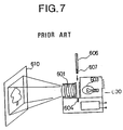
- Fig. 7 shows a conventional liquid crystal display device disclosed in the Japanese Utility Model Application Laid-open Publication 61-119145.
- the device comprises a slide projector 600 in which a light source 603 and a plurality of lenses 601 are provided.
- a liquid crystal display panel module 606 is adapted to attach to the projector 600 and electrically connect thereto through a connector 607 of the module 606 and a connector 604 of the projector 600.
- the module 606 is illuminated by the light source 603 and an image of the module is magnified by lenses 601 and projected on a screen 601.
- Figs. 8a and 8b show another conventional device disclosed in the Japanese Utility Model Application Laid-open Publication 62-12147.
- a holder 706 is interposed between a light source 702 and a lens 704 in a slide projector 700.
- the holder 706 is adapted to hold a slide film 707 and a liquid crystal display plate 703.
- the holder 706 attached to the projector 700 is reciprocated in the horizontal direction as shown by arrows a and b in Figs. 9a, so that either of the slide 707 and the plate 703 may be selected.
- a tungsten halogen lamp is used for the light source.
- the light emitted from the light source includes the infrared ray having a wavelength of 770 nm or more.
- the material of the liquid crystal display panel absorbs the light including a near infrared ray having a wavelength of 50 ⁇ m or less, thermal motion occurs in the material so the temperature of the material rises.
- the projector is usually provided with a heat absorbing filter to shut off the near infrared ray.
- a light source having a large illuminance When it is intended to increase the magnification of the image so as to provide a bright image on the screen, a light source having a large illuminance must be used. However, quantity of heat in the material increases. If the temperature of the liquid crystal exceeds a predetermined value which is determined in accordance with the material of the liquid crystal, the liquid crystal becomes isotropic, so that no image appears on the display panel. Therefore, it is necessary to take measures for heat. Furthermore, in the case that high contrast of the image is required, polarizers are provided in the liquid crystal display device. However, the polarizers absorb about 50% of the transmitted light the energy of which becomes heat. If the polarizers are attached to glasses forming the liquid crystal display panel, the temperature of the liquid crystal between glasses rises.
- liquid crystal display panel module 606 shown in Fig. 7 nor holders 706 and liquid crystal display plate 703 shown in Fig. 8 are provided with any structures to avoid rise of the temperature of the liquid crystal.
- cooling means comprise constructing lengthwise within a housing, an air passage on either side of the liquid crystal device, and inlet and outlet holes at the respective ends of the housing.
- a fan is also provided at the outlet end of the housing to suck in the fresh air and to pass out the air which has already travelled the length of the housing flowing past and cooling at the same time the liquid crystal and the shielding plates containing a polarized filter.
- the housing when using such cooling means in a liquid crystal display device, the housing must always allow for the free passage of air along the length thereof, and most probably always require the inclusion of a fan in order that the cooling can be carried out efficiently.
- liquid crystal display device which solves this task by comprising the features as set out in claim 1.
- the present invention is characterized in that the supporting portions are made of metal.
- a polarizer is secured to the shielding plate on the rear cover.
- the liquid crystal display panel may be disposed between the front and rear covers interposing spacers.
- a radiating fan is provided for cooling the liquid crystal display panel.
- a small liquid crystal display device 1 comprises a housing 100 made of metal such as aluminum having a front cover 110 and a rear cover 130.
- the front means side of the lens of the slide projector and the rear means the side of the light source.
- the housing 100 has a panel housing portion 101 at a lower portion, and a control circuit housing portion 102 at an upper portion, which are longitudinally arranged.
- a liquid crystal display panel 300 and a control circuit board 400 for controlling the panel 300 are housed in the panel housing portion 101 and the control circuit housing portion 102 as shown by dotted lines of Fig. 1a.
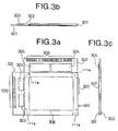
- a lower part of the rear cover 130 is reduced in thickness to form a thinner panel housing 131.
- the front cover 110 has a panel housing 111 to form the panel housing portion 101 together with the panel housing 131, in which the liquid crystal display panel 300 is mounted.
- the front cover 110 and the rear cover 130 have circuit housings 112 and 132 respectively, in which the control circuit board 400 is mounted.
- the panel housing 111 has thin holding portions 113 and 114 formed on opposite sides thereof.
- the panel housing 131 also has thin holding portions 133 and 134 formed on opposite sides thereof, corresponding to holding portions 113 and 114, respectively.
- a left side attached portion composed by holding portions 113 and 133 has a thickness t and a right side attached portion formed by holding portions 114 and 134 also has a thickness t.
- the liquid crystal display device 1 When the liquid crystal display device 1 is attached to a slide projector, the device 1 is engaged with the slide projector at the holding portions 113, 114, 133 and 134.
- the display device 1 has a power switch button 150 on the circuit housing 112, a dial 170 for controlling luminance of the display panel, which is provided on a right side of the housing 100, and an external connector 160 on the top of the housing 100 for receiving an outside signal.
- the housing 100 is made of aluminum in consideration of heat conductivity, workability and portability (specific gravity), other metal such as zinc may be used on the grounds of conductivity and workability.
- Fig. 2 shows a part of the liquid crystal display panel 300 and a part of the control circuit board 400 of the liquid crystal display device 1.
- a panel connecting substrate 200 made of a flexible printed circuit board (FPC) is provided for connecting an internal connector 404 of a control circuit on the circuit board 400 to the liquid crystal display panel 300.
- Front and rear transparent shielding plates 120 and 140 made of acrylic material are provided to close openings 111b and 131b formed in the panel housings 111 and 131, respectively, for protecting the display panel 300.
- Each shielding plate is mounted on the panel housing 111 (131) so that a space 120a is formed between the shielding plate and the display panel 300.
- a pair of polarizers 125 and 145 are attached to the front and rear shielding plates 120 and 140 at inner surfaces thereof, respectively.
- a liquid crystal cell 350 for correcting phase is attached to the liquid crystal display panel 300 with an adhesive tape 195.
- the integrated liquid crystal display panel 300 and the phase correcting cell 350 are mounted between holding projections 111a and 131a formed on the panel housing 111 and 131.
- the display panel 300 and phase correcting cell 350 are employed with liquid crystal having super twisted nematic (STN) display mode. Therefore, the liquid crystal display panel is capable of producing image having a high contrast.
- STN super twisted nematic
- the liquid crystal display panel produces colors on the image.
- the phase correcting cell 350 is used.
- the liquid crystal display panel 300 comprises a glass 301 having scanning electrodes thereon, a glass 302 having signal electrodes thereon, and liquid crystal injected between glasses 301 and 302 through a hole which is sealed by a plug 307.
- a necessary process for orientating molecules of liquid crystal is performed on glasses 301 and 302.
- Driving circuits for driving the display panel 300 are provided on the glasses 301 and 302 in the form of chips, which is called chip-on-glass (COG) method.
- the glass 301 has scanning electrode driving circuit chips 303 mounted thereon and input terminals 305 for scanning electrode driving circuit chips 303.
- the glass 302 has signal electrode driving circuit chips 304 mounted thereon and input terminals 306 for signal electrode driving circuit chips 304. These chips are adhered to the glasses by paste.
- the image is displayed in a region defined by a dot-dash line 308.
- the projections 111a and 131a are disposed at four corners of the overlapped portion of the glasses 301 and 302 so as to form a space between the panel housings 111 and 131 and display panel 300.
- a liquid crystal display device 2 of the second embodiment comprises a housing 100A having a front cover 119 and a rear cover 139 made of plastics formed by means of injection molding.
- a pair of supporting frames 115 and 135 made of aluminum are integrally secured to the front and rear covers 119 and 139, respectively for supporting the front and rear shielding plates 120 and 140.
- the front shielding plate 120 having the polarizer 125 is secured to the supporting frame 115 with an adhesive tape (not shown).
- the rear shielding plate 140 having the polarizer 145 is secured to the supporting frame 135 with an adhesive tape (not shown).
- supporting frames 115 and 135 are made of aluminum, other metal such as zinc, iron or stainless steel can be used because the frame has a simple sectional shape.
- the liquid crystal display device 3 has the housing 100 of the first embodiment.
- the housing 100 further has a spacer 116 disposed between the panel housing 111 and the liquid crystal display panel 300 and a spacer 136 disposed between the panel housing 131 and the phase correcting cell 350.
- These spacers 116 and 136 are made of plastics and secured to the panel housings 111 and 131 with adhesive tapes (not shown).
- Other structures are the same as the first embodiment and the same parts thereof are identified with the same reference numerals as Figs. 1 to 3.
- plastic spacers are disposed between the metal housing and the liquid crystal display panel so that heat conduction from the housing to the liquid crystal display panel can be prevented. Thus, rise of the temperature of the liquid crystal is effectively avoided.
- a housing 100B of a liquid crystal display device 4 has a radiating fan 180 which is secured to a circuit housing 112′ by screws 190.
- the circuit housing 112′ has an opening 180a for passing cooling air.
- a panel housing 111′ has a plurality of air inlet holes 185 formed on a lower portion thereof.
- the liquid crystal display panel 300 integrated with the phase correcting cell 350 is mounted between projections 111a and 131a as shown in Figs. 2 and 3a.
- Other structures are the same as the first embodiment and the same parts thereof are identified with the same reference numerals as Figs. 1 to 3.
- each of the above described liquid crystal display panel has a phase correcting cell and a pair of polarized plates, these elements are not employed for a liquid crystal display panel using the guest-host display mode, or at least one polarized plate is employed.
- the phase correcting cell 350 is provided for the black and white display, the present invention may be applied to a liquid crystal panel without the phase correcting cell which provide blue mode or yellow mode.
- the housing of the liquid crystal display device is made of metal, the heat of air in the spaces surrounding the crystal display panel, which is increased by the energy of the light emitted from the light source of the projector, is transmitted to the metal housing.
- the temperature of the liquid crystal in the liquid crystal display panel can be prevented from rising.
- the polarizer absorbs about 50% of the incident light. Therefore, heat absorbed in the polarizer can be transmitted to the housing by attaching the polarizer to the shielding plates. If there is a temperature difference between a central portion and a peripheral portion of the liquid crystal display panel, the image on the display panel comes irregular. In accordance with the present invention, since the temperature is equalized, such an irregular image does not occur.
- driving circuit chips are adhered to glasses of the display panel with paste, connection between electrodes and circuit chips can be maintained in safety, by preventing the temperature of the liquid crystal from rising.
Landscapes
- Physics & Mathematics (AREA)
- Nonlinear Science (AREA)
- Mathematical Physics (AREA)
- Chemical & Material Sciences (AREA)
- Crystallography & Structural Chemistry (AREA)
- General Physics & Mathematics (AREA)
- Optics & Photonics (AREA)
- Liquid Crystal (AREA)
- Devices For Indicating Variable Information By Combining Individual Elements (AREA)
Claims (5)
- Eine Flüssigkristallanzeigevorrichtung, die zwischen eine Lichtquelle (702) und eine Linse (704) eines Stehbildprojektors (700) zur Projektion eines Bildes auf einen Schirm eingefügt ist, umfassend:
ein Gehäuse (100), das eine Vorderabdeckung (110) und eine Rückabdeckung (130) umfaßt, das zur Bildung eines Plattengehäusebereiches (101) und eines Steuerschaltkreisgehäusebereiches (102) vorgesehen ist;
eine Flüssigkristallanzeigeplatte (300), die in dem Plattengehäusebereich eingeschlossen ist;
einen Steuerschaltkreis, der in dem Steuerschaltkreisgehäusebereich eingeschlossen ist;
ein Paar von transparenten Abschirmplatten (120, 140), die an den Vorder- und Rückabdeckungen zum Verschluß von Öffnungen, die in dem Plattengehäusebereich an gegenüberliegenden Seiten der Flüssigkristallanzeigeplatte gebildet sind, befestigt und so angebracht sind, daß ein Abstand zwischen der Abschirmplatte und der gegenüberliegenden Seite der Flüssigkristallanzeigeplatte gebildet wird; und
mindestens einen Polarisator (145), der an einer Innenseite von einer der Abschirmplatten befestigt ist; wobei
jede der Vorder- und Rückabdeckungen (110, 130) an dem Plattengehäusebereich einen Tragebereich (111, 131, 115, 135) aufweisen;
jede der Abschirmplatten (120, 140) auf einer Ausnehmung angebracht ist, die auf dem Tragebereich gebildet ist, so daß die Oberfläche der Abschirmplatte mit der Oberfläche des Tragebereiches fluchtend ist; und
Haltevorsprünge (111a, 131a) an der Unterseite eines jeden Tragebereiches (111, 131, 115, 135) zum Tragen der Flüssigkristallanzeigeplatte vorgesehen sind,
dadurch gekennzeichnet, daß
die Tragebereiche aus Metall hergestellt sind. - Flüssigkristallanzeigevorrichtung gemäß Anspruch 1, bei der das Gehäuse aus Aluminium hergestellt ist.
- Flüssigkristallanzeigevorrichtung gemäß Anspruch 1, wobei jeder der Haltevorsprünge durch einen Abstandshalter (116, 136) gebildet wird, der aus Kunststoff hergestellt und an der Unterseite des Tragebereiches angebracht ist.
- Flüssigkristallanzeigevorrichtung gemäß Anspruch 1, wobei jeder der Tragebereiche durch ein Plattengehäuse (111, 131) gebildet wird, welches einstückig mit der Abdeckung (110, 130) ist.
- Flüssigkristallanzeigevorrichtung gemäß Anspruch 1, wobei jeder der Tragebereiche durch einen Rahmen (115, 135) gebildet wird, der an der Abdeckung befestigt ist.
Applications Claiming Priority (4)
| Application Number | Priority Date | Filing Date | Title |
|---|---|---|---|
| JP110265/88U | 1988-08-23 | ||
| JP1988110265U JPH0746902Y2 (ja) | 1988-08-23 | 1988-08-23 | 小型液晶表示装置 |
| JP1988155413U JPH0755535Y2 (ja) | 1988-11-29 | 1988-11-29 | 小型液晶表示装置 |
| JP155413/88U | 1988-11-29 |
Publications (2)
| Publication Number | Publication Date |
|---|---|
| EP0361074A1 EP0361074A1 (de) | 1990-04-04 |
| EP0361074B1 true EP0361074B1 (de) | 1995-11-15 |
Family
ID=26449936
Family Applications (1)
| Application Number | Title | Priority Date | Filing Date |
|---|---|---|---|
| EP89115483A Expired - Lifetime EP0361074B1 (de) | 1988-08-23 | 1989-08-22 | Flüssigkristall-Anzeigevorrichtung |
Country Status (4)
| Country | Link |
|---|---|
| US (1) | US4963001A (de) |
| EP (1) | EP0361074B1 (de) |
| DE (1) | DE68924823T2 (de) |
| HK (1) | HK164396A (de) |
Families Citing this family (38)
| Publication number | Priority date | Publication date | Assignee | Title |
|---|---|---|---|---|
| JPH087386Y2 (ja) * | 1988-07-26 | 1996-03-04 | シチズン時計株式会社 | 小型液晶表示装置 |
| USD320403S (en) | 1988-09-12 | 1991-10-01 | Honeywell, Inc. | Liquid crystal screen for overhead projector |
| EP0375425A3 (de) * | 1988-12-22 | 1991-09-18 | Seiko Instruments Inc. | Projektionsplatte mit einer Flüssigkristalltafel |
| AU7166291A (en) * | 1989-12-22 | 1991-07-24 | Manufacturing Sciences, Inc. | Programmable masking apparatus |
| NL9000115A (nl) * | 1990-01-18 | 1991-08-16 | Philips Nv | Inrichting voor het projecteren van televisiebeelden. |
| JPH03241392A (ja) * | 1990-02-20 | 1991-10-28 | Casio Comput Co Ltd | 表示パネルの実装構造 |
| US5396304A (en) * | 1990-12-31 | 1995-03-07 | Kopin Corporation | Slide projector mountable light valve display |
| US5376979A (en) * | 1990-12-31 | 1994-12-27 | Kopin Corporation | Slide projector mountable light valve display |
| US5743614A (en) * | 1990-12-31 | 1998-04-28 | Kopin Corporation | Housing assembly for a matrix display |
| US5317436A (en) * | 1990-12-31 | 1994-05-31 | Kopin Corporation | A slide assembly for projector with active matrix moveably mounted to housing |
| US5287132A (en) * | 1991-02-16 | 1994-02-15 | Fuji Photo Film Co., Ltd. | Video projector |
| JP2548677Y2 (ja) * | 1991-05-10 | 1997-09-24 | シャープ株式会社 | 液晶用照明装置 |
| JP3736770B2 (ja) * | 1992-01-22 | 2006-01-18 | コピン・コーポレーシヨン | 映写表示のための単結晶シリコンアレイデバイス |
| US6511187B1 (en) | 1992-02-20 | 2003-01-28 | Kopin Corporation | Method of fabricating a matrix display system |
| JPH0651250A (ja) * | 1992-05-20 | 1994-02-25 | Texas Instr Inc <Ti> | モノリシックな空間的光変調器およびメモリのパッケージ |
| USD355206S (en) | 1993-02-10 | 1995-02-07 | Kopin Corporation | Liquid crystal display housing unit adapted for use with a slide projector |
| USD353390S (en) | 1993-02-10 | 1994-12-13 | Kopin Corporation | Liquid crystal display housing unit for a slide projector |
| JPH06258637A (ja) * | 1993-03-04 | 1994-09-16 | Sony Corp | 液晶表示装置 |
| USD352304S (en) | 1993-10-14 | 1994-11-08 | Kopin Corporation | Liquid crystal display housing unit adapted for use with a slide projector |
| US5664859A (en) * | 1994-01-03 | 1997-09-09 | Kopin Corporation | Projection display docking system |
| US5416541A (en) * | 1994-05-16 | 1995-05-16 | Fog; Stephen C. | Folding portable overhead projector |
| US5550604A (en) * | 1994-06-03 | 1996-08-27 | Kopin Corporation | Compact high resolution light valve projector |
| US5806950A (en) * | 1994-06-03 | 1998-09-15 | Kopin Corporation | Compact high resolution light valve projector |
| US5666171A (en) * | 1994-08-02 | 1997-09-09 | Casio Computer Co., Ltd. | Liquid crystal image projector |
| USD368730S (en) | 1994-09-28 | 1996-04-09 | Kopin Corporation | Compact light valve projector |
| US5630659A (en) * | 1994-09-28 | 1997-05-20 | Kopin Corporation | Compact high resolution light valve projector |
| JPH09113998A (ja) * | 1995-10-18 | 1997-05-02 | Sony Corp | 液晶パネルユニットおよび液晶プロジェクタ |
| US5682216A (en) * | 1996-04-01 | 1997-10-28 | Ctx Opto-Electronics Corp. | LCD projector capable of preventing thermal shimmering by using a thermal diffusion film |
| JPH09284685A (ja) * | 1996-04-17 | 1997-10-31 | Hitachi Ltd | 投写形液晶ディスプレイ装置 |
| JP3889090B2 (ja) * | 1996-08-28 | 2007-03-07 | 株式会社東芝 | シート保持装置 |
| DE19642617C2 (de) * | 1996-09-12 | 1999-12-09 | Michael Liebhardt | Anzeigeeinheit und Projektionsvorrichtung für Bildsequenzen |
| US6545654B2 (en) | 1996-10-31 | 2003-04-08 | Kopin Corporation | Microdisplay for portable communication systems |
| AUPO544897A0 (en) * | 1997-03-05 | 1997-03-27 | Banks, Philip Brendan | Video projector |
| US6246459B1 (en) | 1998-06-10 | 2001-06-12 | Tyco Electronics Corporation | Assembly including an active matrix liquid crystal display module and having plural environmental seals |
| US6967697B2 (en) | 2000-12-15 | 2005-11-22 | Kopin Corporation | Display housing with a display alignment device |
| JP5504557B2 (ja) * | 2007-09-21 | 2014-05-28 | セイコーエプソン株式会社 | 電気光学装置及び電気光学装置用実装ケース、並びに電子機器 |
| JP6047873B2 (ja) * | 2011-11-09 | 2016-12-21 | セイコーエプソン株式会社 | 電気光学モジュールおよび電子機器 |
| CN104007573A (zh) * | 2014-04-18 | 2014-08-27 | 京东方光科技有限公司 | 显示面板、膜材的贴附方法及显示面板的制备方法 |
Family Cites Families (8)
| Publication number | Priority date | Publication date | Assignee | Title |
|---|---|---|---|---|
| US4357061A (en) * | 1980-02-28 | 1982-11-02 | Beckman Instruments, Inc. | Electro-mechanical package of visual display and related circuitry |
| DE3413995A1 (de) * | 1984-04-13 | 1985-10-17 | Demolux Gmbh & Co Kg, 6070 Langen | Overhead-projektor |
| JPS6119282U (ja) * | 1984-07-06 | 1986-02-04 | シャープ株式会社 | 表示装置 |
| EP0192023A3 (de) * | 1985-02-21 | 1986-10-08 | Casio Computer Company Limited | Flüssigkristallprojektor |
| WO1987007394A1 (fr) * | 1986-05-27 | 1987-12-03 | Bernd Haastert | Affichage a cristaux liquides passif projetable |
| US4904079A (en) * | 1986-08-13 | 1990-02-27 | Sharp Kabushiki Kaisha | Liquid crystal display device for overhead projector |
| JPS6338180U (de) * | 1986-08-26 | 1988-03-11 | ||
| US4763993A (en) * | 1987-04-30 | 1988-08-16 | N-View Corporation | Liquid crystal display for projection systems |
-
1989
- 1989-08-22 DE DE68924823T patent/DE68924823T2/de not_active Expired - Fee Related
- 1989-08-22 EP EP89115483A patent/EP0361074B1/de not_active Expired - Lifetime
- 1989-08-22 US US07/396,673 patent/US4963001A/en not_active Expired - Fee Related
-
1996
- 1996-09-05 HK HK164396A patent/HK164396A/en not_active IP Right Cessation
Also Published As
| Publication number | Publication date |
|---|---|
| DE68924823T2 (de) | 1996-05-02 |
| EP0361074A1 (de) | 1990-04-04 |
| DE68924823D1 (de) | 1995-12-21 |
| HK164396A (en) | 1996-09-13 |
| US4963001A (en) | 1990-10-16 |
Similar Documents
| Publication | Publication Date | Title |
|---|---|---|
| EP0361074B1 (de) | Flüssigkristall-Anzeigevorrichtung | |
| US6498672B2 (en) | Electro-optical device and projection display device including the same | |
| JP3414399B2 (ja) | 液晶表示ユニット及び液晶表示ユニットを用いた液晶プロジェクタ | |
| US7139062B2 (en) | Display panel assembly, display panel case, display panel module, projection display device, and cooling method for the display panel module | |
| US5155612A (en) | Liquid crystal display device with light shield | |
| US6375328B2 (en) | Optical modulation element and projector | |
| US20020036815A1 (en) | Optical modulation device and projection display device utilizing the optical modulation device | |
| KR102068959B1 (ko) | 액정표시장치 | |
| US6950308B2 (en) | Electro-optical device encased in mounting case, projection display apparatus, and mounting case | |
| US9423640B2 (en) | Display device comprising a first positioning portion opposite to a second positioning portion and television device having the same | |
| KR100650399B1 (ko) | 액정표시장치용 분리형 인쇄회로기판 | |
| KR102116441B1 (ko) | 액정표시장치 | |
| US7245334B2 (en) | Electro-optical device encased in mounting case, projection display apparatus, and mounting case | |
| JP2003248214A (ja) | 電気光学装置及びこれを備えた投射型表示装置 | |
| TW200422767A (en) | Cased electro-optical apparatus, projection display apparatus, and case | |
| JP2547984B2 (ja) | 投写型表示装置 | |
| JP4389836B2 (ja) | 液晶装置及びこれを備えた投射表示装置 | |
| KR20050007512A (ko) | 액정표시장치 | |
| KR101333267B1 (ko) | 액정표시장치 | |
| JPH0755535Y2 (ja) | 小型液晶表示装置 | |
| JPH0746902Y2 (ja) | 小型液晶表示装置 | |
| JP3808366B2 (ja) | 液晶表示装置 | |
| JP2569848B2 (ja) | 液晶表示装置 | |
| JP2007304393A (ja) | プロジェクタ | |
| KR101291973B1 (ko) | 액정표시장치 |
Legal Events
| Date | Code | Title | Description |
|---|---|---|---|
| PUAI | Public reference made under article 153(3) epc to a published international application that has entered the european phase |
Free format text: ORIGINAL CODE: 0009012 |
|
| AK | Designated contracting states |
Kind code of ref document: A1 Designated state(s): DE GB |
|
| 17P | Request for examination filed |
Effective date: 19901002 |
|
| 17Q | First examination report despatched |
Effective date: 19920807 |
|
| GRAA | (expected) grant |
Free format text: ORIGINAL CODE: 0009210 |
|
| AK | Designated contracting states |
Kind code of ref document: B1 Designated state(s): DE GB |
|
| REF | Corresponds to: |
Ref document number: 68924823 Country of ref document: DE Date of ref document: 19951221 |
|
| PLBE | No opposition filed within time limit |
Free format text: ORIGINAL CODE: 0009261 |
|
| STAA | Information on the status of an ep patent application or granted ep patent |
Free format text: STATUS: NO OPPOSITION FILED WITHIN TIME LIMIT |
|
| 26N | No opposition filed | ||
| PGFP | Annual fee paid to national office [announced via postgrant information from national office to epo] |
Ref country code: GB Payment date: 19970813 Year of fee payment: 9 |
|
| PG25 | Lapsed in a contracting state [announced via postgrant information from national office to epo] |
Ref country code: GB Free format text: LAPSE BECAUSE OF NON-PAYMENT OF DUE FEES Effective date: 19980822 |
|
| GBPC | Gb: european patent ceased through non-payment of renewal fee |
Effective date: 19980822 |
|
| PGFP | Annual fee paid to national office [announced via postgrant information from national office to epo] |
Ref country code: DE Payment date: 19990823 Year of fee payment: 11 |
|
| PG25 | Lapsed in a contracting state [announced via postgrant information from national office to epo] |
Ref country code: DE Free format text: LAPSE BECAUSE OF NON-PAYMENT OF DUE FEES Effective date: 20010501 |