EP0361075B1 - Sicherheitsgurtvorrichtung - Google Patents
Sicherheitsgurtvorrichtung Download PDFInfo
- Publication number
- EP0361075B1 EP0361075B1 EP89115489A EP89115489A EP0361075B1 EP 0361075 B1 EP0361075 B1 EP 0361075B1 EP 89115489 A EP89115489 A EP 89115489A EP 89115489 A EP89115489 A EP 89115489A EP 0361075 B1 EP0361075 B1 EP 0361075B1
- Authority
- EP
- European Patent Office
- Prior art keywords
- shoes
- cable
- shaft
- arrangement according
- tension
- Prior art date
- Legal status (The legal status is an assumption and is not a legal conclusion. Google has not performed a legal analysis and makes no representation as to the accuracy of the status listed.)
- Expired
Links
- 239000000463 material Substances 0.000 claims description 16
- 229920003023 plastic Polymers 0.000 claims description 9
- 239000004033 plastic Substances 0.000 claims description 9
- 238000000465 moulding Methods 0.000 claims description 5
- 210000003739 neck Anatomy 0.000 claims description 5
- 239000002184 metal Substances 0.000 description 5
- 238000004804 winding Methods 0.000 description 2
- 230000000694 effects Effects 0.000 description 1
- 238000002347 injection Methods 0.000 description 1
- 239000007924 injection Substances 0.000 description 1
- 238000004519 manufacturing process Methods 0.000 description 1
- 238000003801 milling Methods 0.000 description 1
- 230000002093 peripheral effect Effects 0.000 description 1
- 230000000452 restraining effect Effects 0.000 description 1
Images



Classifications
-
- B—PERFORMING OPERATIONS; TRANSPORTING
- B60—VEHICLES IN GENERAL
- B60R—VEHICLES, VEHICLE FITTINGS, OR VEHICLE PARTS, NOT OTHERWISE PROVIDED FOR
- B60R22/00—Safety belts or body harnesses in vehicles
- B60R22/34—Belt retractors, e.g. reels
- B60R22/46—Reels with means to tension the belt in an emergency by forced winding up
- B60R22/4619—Transmission of tensioning power by cable, e.g. using a clutch on reel side
-
- B—PERFORMING OPERATIONS; TRANSPORTING
- B60—VEHICLES IN GENERAL
- B60R—VEHICLES, VEHICLE FITTINGS, OR VEHICLE PARTS, NOT OTHERWISE PROVIDED FOR
- B60R22/00—Safety belts or body harnesses in vehicles
- B60R22/34—Belt retractors, e.g. reels
- B60R22/46—Reels with means to tension the belt in an emergency by forced winding up
- B60R2022/468—Reels with means to tension the belt in an emergency by forced winding up characterised by clutching means between actuator and belt reel
Definitions
- THE PRESENT INVENTION relates to a safety belt arrangement and more particularly to a safety belt arrangement for use in restraining a passenger in a motor vehicle, such as a motor car.
- a pre-tensioner adapted to apply a tension to the belt, in the event that an accident situation should arise. Since the locking arrangement present in a conventional retractor reel takes some time to be actuated, it is often the case that a certain length of safety belt has been paid out, from the reel, before the locking mechanism serves to lock the reel. The length of safety belt that has been paid out may be sufficient to permit the passenger restrained by the safety belt to travel forwardly, relative to his seat, which means that the passenger may then be in a position where he can hit the windscreen of the motor vehicle with his head. However, if a pre-tensioner is provided, when an accident situation is sensed, a tension is applied to the safety belt which serves to prevent this happening, retaining the passenger firmly in his seat.
- pre-tensioner Various types have been proposed before, and certain pre-tensioners have been proposed which serve to rotate the shaft of the retractor reel in order to wind a length of safety belt on to the reel when an accident situation arises.
- US-A-4423846 discloses a pre-tensioner of this type.
- a force is applied to a cable which is applied to a drum.
- the drum is provided with elements which, on rotation of the drum, engage fixed pegs and are thus moved to a condition where they engage a splined extension of the shaft of the retractor reel.
- tension applied by the cable causes the shaft of the retractor reel to rotate, winding safety belt on to the shaft of the retractor reel.
- this movement of the drum also snaps the pegs.
- the elements become disengaged from the splined extension of the shaft there is nothing to re-engage them with the shaft.
- the described arrangement is relatively complex and difficult to assemble.
- the present invention seeks to provide an improved safety belt arrangement incorporating a pre-tensioner adapted to rotate the shaft of a retractor reel.
- a safety belt arrangement comprising a safety belt mounted on a shaft of a retractor reel adapted to retract part of the safety belt, a pre-tensioner assembly adapted to apply tension to a cable or the like, the cable being wound round a mechanism incorporating a plurality of elements which are mounted for pivotal movement in response to tension being applied to the cable from an initial position in which the elements are spaced from an extension of the shaft of the retractor reel to an engagement position in which the elements engage the extension of the shaft of the retractor reel, continuing tension applied to the cable causing the elements and the shaft to rotate about the axis of the shaft, means being provided to retain the elements in the initial position, wherein the elements comprise shoes each pivotally mounted for rotation about a respective pivot, the cable or the like being wound round the outer periphery of the shoes so that the shoes pivot radially inwardly to engage the shaft extension in response to a radially inwardly acting force applied to the shoes by the cable when said tension is applied to the cable, the pivots being mounted on
- the cable acts directly on the shoes, there is no need to provide the drum or the fixed pegs present in the prior art arrangement. Also, it will be appreciated, that the cable will keep the shoes in engagment with the extension of the shaft for as long as tension is applied to the cable. Thus there is no risk of the shoes becoming disengaged from the extension of the shaft inadvertently.
- the said means to retain the shoes in the first condition comprise resilient means, such as springs.
- the springs may be separate discrete springs, or may be formed integrally with the shoes.
- each shoe is pivotally mounted, each shoe being of generally arcuate form and being pivotally mounted adjacent one end thereof.
- the shoes are pivotally mounted at their trailing edges considered in the sense of the direction of rotation of the shoes when tension is applied to said cable or the like.
- the shoes are pivotally mounted on pivot pins which have axes extending parallel with the axis of the shaft of the retractor reel, the pivot pins being mounted on a ring-shaped element, means being provided initially to retain the ring-shaped element in a predetermined position.
- said means to retain the ring-shaped element in a predetermined position comprise narrow necks of material joining the ring-shaped element to a further part of the structure of the safety belt arrangement, the necks of material being frangible.
- each shoe is roughened, and the outer surface of the extension of the shaft of the retractor reel is similarly roughened.
- a plurality of shoes are provided, the shoes being formed as an integral moulding of a plastics material.
- the shoes are integrally moulded with interconnecting webs which constitute resilient means which retain the shoes in said initial condition.
- the shoes are integrally moulded of a plastics material, the shoes being interconnected by frangible webs which constitute the means to retain the shoes at the initial position.
- auxilliary spring means are provided in the form of a metal washer provided with axially extending resilient arms which engage said shoes to bias the shoes towards the initial position.
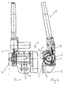
- a safety belt arrangement in accordance with the present invention comprises a conventional retractor reel assembly 1 which incorporates a shaft portion 2 on which a safety belt may be wound, and which also incorporates a cover 3 covering a locking mechanism for locking the shaft 2 under predetermined accident conditions.
- the retractor reel assembly is provided with a mounting plate 4 provided with apertures 5 to receive mounting bolts.
- the rectangular reel assembly also incorporates a spring to apply a rotational force to the shaft 2.
- the retractor reel assembly may be of conventional design.
- the extension 6 is extended to form an extension 6.
- the extension 6 is provided with a roughened outer surface 7 which may be constituted by milling or splines.
- Three arcuate shoes 8 are provided which are mounted adjacent the extension 6 of the shaft 2.
- the shoes are of arcuate form, and the radially inner surface 9 of each shoe is roughened, for example milled or grooved to engage with the roughened surface 7 provided on the extension 6.
- Each shoe 8 is pivotally mounted for rotation about a pivot pin 10.
- the axes of the pivot pins 10 are parallel with the axis of the shaft 2.
- Each pivot pin 10 is located adjacent one end of the respective shoe 8.
- the shoes are biassed, by means of resilient biassing means constituted by springs 11, to positions, as illustrated in Figure 8, in which the inner surfaces 9 of the shoes 8 are spaced from the outer surface 7 of the extension 6 of the shaft 2.
- the pivot pins 10 are formed on a ring-shaped element which is obscured in Figure 2 by the shoes.
- the ring-shaped element is secured to the adjacent part of the retractor reel assembly 1 by means of shearable pins or the like.
- a pre-tensioner 12 is provided which may comprise a mechanical device or a pyrotechnic device.
- the pre-tensioner is adapted, when activated, to apply tension to a cable 13, serving to withdraw the cable 13 into the pre-tensioner assembly 12.
- the cable 13 is wrapped, with several turns, around the exterior of the three shoes 8, and the free end of the cable is connected to one of the shoes.
- the shoes are in an initial position in which they do not engage the extension 6.
- a tension is applied to the cable 13
- initially the tension in the cable serves to cause each shoe 8 to pivot about the respective pivot pin 10, against the bias provided by the springs 11, so that the inner surface 9 of each shoe is brought into firm non-slipping engagement with the outer surface 7 of the extension 6 of the shaft 2.
- the shoes are thus in an engaging position.
- Further tension causes the shearable pins associated with the ring supporting the pivot pins 10 to break, enabling the ring on which the pivot pins 10 are mounted to rotate in an anti-clockwise direction, as seen in Figure 2.
- This serves to rotate the shaft 2 in an anti-clockwise direction, winding on to the shaft a length of safety belt.
- the safety belt is pre-tensioned.
- the cable 13 may be released, and the springs 11 serve to bias the shoes 8 outwardly, thus releasing the shoes from the extension 6 of the shaft 2.
- the retractor reel assembly 1 is then free to operate in its normal way.
- the shoes 8 are each pivotally mounted about pivot axes 10 located adjacent the trailing edges of the shoes, when considered in the direction in which the shoes rotate when tension is applied to the cable 13.
- the cable effectively passes from the trailing edge to the leading edge of each shoe. It is thought that this helps ensure that the shoes move rapidly to the engaging position when tension is applied to the cable 13.
- the shoes 8 may be formed of any suitable material, and may thus be formed of metal or may be formed of plastics material.
- FIGS 3 to 5 illustrate a housing 14 which is used in a modified embodiment of the invention and which incorporates the pivot pins 10 upon which the shoes 8 as described above may be mounted.
- the housing 14 may be injection moulded or die cast from any suitable material such as metal or plastics.
- the housing incorporates a central circular chamber 15, and a guide channel 16 through which the cable 13 may enter the chamber 15.
- the chamber 15 is dimensioned to receive the extension 6 of the shaft 2 together with the shoes 8 and the associated springs 11.
- the base of the chamber 15 is provided with a central aperture 17 through which part of the shaft 2 may pass.
- pivot pins 10 are mounted on an annular portion 18 of the base of the chamber 15, which is separated from the rest of the base by a plurality of arcuate slots 19 so that the annular portion 18 is only connected to the rest of the base by three relatively narrow necks of material 20. It is thus to be understood that in normal circumstances the pivot pins 10 are fixed in position. Consequently, in normal circumstances, the shoes 8 are not free to rotate about the axis of the shaft 2.
- FIG. 6 illustrates a modified embodiment of the invention in which an integral shoe and spring assembly 21 is provided, which is illustrated as being mounted in a housing 14 as described above.
- the shoe and spring assembly 21 is formed as an integral moulding of a plastics material.
- the moulding defines three shoe portions 22 which are interconnected by relatively narrow webs 23 which comprise biassing springs, which function in the same way as the springs 11.
- the shoe portions each define an aperture or recess 24 adapted to pivotally engage a pivot pin 10.
- the shoe portions are each pivotally mounted adjacent their trailing edge.
- the cable 13 from the pre-tensioner passes, with several turns, around the outsides of the shoes, the cable being received in grooves 25 defined in the rear surfaces of the shoes.
- the free end of the cable is provided with an enlargement or stop 26 which engages an abutment face 27 defined on the appropriate shoe portion.
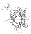
- FIG. 7 illustrates another embodiment of the invention, but again this embodiment incorporates a housing 14 as described above. Again this embodiment incorporates an integrally formed shoe assembly 28.
- the shoe assembly 28 consists of three shoe elements 29, which are formed as an integral moulding of a plastics material, but the shoe elements 29 are interconnected by relatively thin interconnecting webs 30 which are adapted to break if the shoes move relative to one another. The webs serve to prevent the shoes moving prematurely to the engaging position, for example when the motor vehicle travels over a rough surface.
- Mounted adjacent the shoes is a washer 31 formed of a metal which is provided with substantially axially extending resilient arms 32 which engage portions of the shoes to effect a resilient outward bias.
- Figure 8 is a sectional view through part of the washer, showing a peripheral portion of the washer 31 and the axially extending resilient arm 32.
- the cable 13 passes through grooves 33 formed in the exterior of each shoe, and again the cable is terminated with an enlargement or termination 34 which abuts against an abutment surface 35 defined on the appropriate shoe.
- This embodiment of the invention is to be preferred to the embodiment illustrated in Figure 6 where the reel is to be submitted to extremes of temperature, since in extreme temperatures a spring formed of a web of plastics material (such as the web 23) may not function properly.
- a spring such as provided by a metal washer 31 provided with extending resilient arms 32 provides more uniform properties over a wide range of temperatures.
- Figures 9A and 9B show another possible structure for the shoes.
- a ring-shaped element 33 formed of a sheet material has three outwardly extending arms 34 as shown in Figure 9A.
- the arms may be bent to extend out of the plane of the ring as shown in Figure 9B.
- the arms then form pivots.
- the free ends of the arms carry projections 35, which may be corrugated, which can then act as shoes in the manner described above.
Landscapes
- Engineering & Computer Science (AREA)
- Mechanical Engineering (AREA)
- Automotive Seat Belt Assembly (AREA)
Claims (10)
- Sicherheitsgurtvorrichtung, die einen Sicherheitsgurt, der auf einer Welle (2) eines Rückhohlaufspulers (1), der einen Teil des Sicherheitsgurtes zurückholen kann, angebracht ist; eine Vorspannungseinrichtung (12), die eine Spannung an ein Kabel (13) oder dergleichen anlegen kann, wobei das Kabel um eine Einrichtung herum gewunden wird, die eine Vielzahl von Elementen (8, 22, 28) umfaßt, die zur Drehbewegung in Antwort auf an das Kabel angelegte Spannung von einer ursprünglichen Stellung, in welcher die Elemente von einem Ausläufer (6) der Welle (2) des Rückholaufspulers entfernt angeordnet sind, in eine Verbindung herstellende Stellung angebracht sind, in welcher die Elemente an den Ausläufer der Welle des Rückholaufspulers ankoppeln, wobei kontinuierlich an das Kabel angelegte Spannung dafür sorgt, daß die Elemente und die Welle um die Achse der Welle rotieren; und Mittel (11, 23, 32), die zur Verfügung gestellt werden, um die Elemente in einer ursprünglichen Position zurückzuhalten, umfaßt, gekennzeichnet dadurch, daß die Elemente (8, 21, 28) Schuhe umfassen, wobei jeder davon zur Drehung um eine entsprechende Drehachse (10) drehbar angebracht ist, das Kabel (13) oder dergleichen um den äußeren Umfang der Schuhe herumgewickelt wird, so daß die Schuhe radial nach innen drehen, um eine Verbindung mit dem Wellenausläufer in Antwort auf eine radial nach innen wirkende Kraft, die durch das Kabel an die Schuhe angelegt wird, wenn besagte Spannung an das Kabel angelegt wird, herzustellen, wobei die Drehachsen (10) auf einem Element (18) angebracht sind, welches rotieren kann, wenn Spannung an das Kabel angelegt worden ist.
- Vorrichtung nach Anspruch 1, dadurch gekennzeichnet, daß besagtes Mittel zum Zurückhalten der Schuhe gemäß der ersten Bedingung Federn (11, 23) umfaßt.
- Vorrichtung nach Anspruch 2, dadurch gekennzeichnet, daß die Federn (23) in einem mit den Schuhen (22) ausgebildet sind.
- Vorrichtung nach irgendeinem der vorangegangenen Ansprüche, dadurch gekennzeichnet, daß die Schuhe (8, 22, 28) jeweils, im allgmeinen, von gebogener Form sind, und jeweils drehbar angebracht sind, wobei die jeweiligen Enden benachbart zueinander sind.
- Vorrichtung nach Anspruch 4, dadurch gekennzeichnet, daß die Schuhe (8, 22, 28) drehbar an ihren hinteren Kanten bezüglich der Rotationsrichtung der Schuhe, wenn Spannung an besagtes Kabel (13) oder dergleichen angelegt wird, angebracht sind.
- Vorrichtung nach Anspruch 4 oder 5, dadurch gekennzeichnet, daß die Schuhe drehbar auf Drehachsenstützern (10) angebracht sind, welche eine Achse haben, die sich parallel zur Achse der Welle des Rückholaufspulers erstreckt, wobei die Drehachsenstützer auf einem ringförmigen Element (18) angebracht sind, und anfänglich scherbare Mittel (20) zur Verfügung gestellt werden, um das ringförmige Element in einer vorherbestimmten Stellung zu halten.
- Vorrichtung nach Anspruch 6, dadurch gekennzeichnet, daß besagtes scherbare Element zum Zurückhalten des ringförmigen Elements (18) in einer vorherbestimmten Stellung schmale Materialhälse (20) umfaßt, um das ringförmige Element mit einem weiteren Teil (15) des Aufbaues der Sicherheitsgurtvorrichtung zu verbinden.
- Vorrichtung nach einem der vorangegangenen Ansprüche, dadurch gekennzeichnet, daß die innere Oberfläche von jedem Schuh (8, 22, 28) aufgerauht ist, und die äußere Oberfläche des Ausläufers der Welle des Rückholaufspulers auf ähnliche Weise aufgerauht ist.
- Vorrichtung nach irgendeinem der vorangegangenen Ansprüche, dadurch gekennzeichnet, daß eine Vielzahl von Schuhen (22, 28) zur Verfügung gestellt werden, wobei die Schuhe als integrale Ausformung eines Plastikmaterials gebildet werden.
- Vorrichtung nach Anspruch 9, dadurch gekennzeichnet, daß die Schuhe (28) in einem aus einem Plastikmaterial ausgeformt sind, wobei die Schuhe untereinander durch brechbares Gewebe (32) verbunden sind, welches das Mittel zum Zurückhalten der Schuhe in der ursprünglichen Stellung bildet.
Applications Claiming Priority (2)
| Application Number | Priority Date | Filing Date | Title |
|---|---|---|---|
| GB8820936 | 1988-09-07 | ||
| GB8820936A GB2222510B (en) | 1988-09-07 | 1988-09-07 | Improvements in or relating to a safety belt arrangement |
Publications (2)
| Publication Number | Publication Date |
|---|---|
| EP0361075A1 EP0361075A1 (de) | 1990-04-04 |
| EP0361075B1 true EP0361075B1 (de) | 1992-12-23 |
Family
ID=10643165
Family Applications (1)
| Application Number | Title | Priority Date | Filing Date |
|---|---|---|---|
| EP89115489A Expired EP0361075B1 (de) | 1988-09-07 | 1989-08-22 | Sicherheitsgurtvorrichtung |
Country Status (5)
| Country | Link |
|---|---|
| US (1) | US5114090A (de) |
| EP (1) | EP0361075B1 (de) |
| JP (1) | JP2903475B2 (de) |
| DE (1) | DE68904029T2 (de) |
| GB (1) | GB2222510B (de) |
Families Citing this family (20)
| Publication number | Priority date | Publication date | Assignee | Title |
|---|---|---|---|---|
| JPH0392453A (ja) * | 1989-09-04 | 1991-04-17 | Takata Kk | シートベルト装置におけるプリテンショナー |
| JPH0431648U (de) * | 1990-07-13 | 1992-03-13 | ||
| JP2874793B2 (ja) * | 1990-08-08 | 1999-03-24 | 株式会社東海理化電機製作所 | プリロード装置 |
| GB2250419B (en) * | 1990-12-04 | 1994-09-28 | Autoliv Sverige Ab | Improvements in or relating to a pre-tensioner retractor arrangement |
| JP2988536B2 (ja) * | 1991-03-06 | 1999-12-13 | タカタ株式会社 | リトラクタ軸回転式プリテンショナ |
| JP2991792B2 (ja) * | 1991-03-12 | 1999-12-20 | タカタ株式会社 | リトラクタ軸回転式プリテンショナ |
| JPH05246305A (ja) * | 1991-03-12 | 1993-09-24 | Takata Kk | リトラクタ軸回転式プリテンショナ |
| GB9106450D0 (en) * | 1991-03-26 | 1991-05-15 | Europ Components Corp | Safety belt pre-tension assembly |
| DE4124506A1 (de) * | 1991-07-24 | 1993-01-28 | Daimler Benz Ag | Aufblasbares aufprallschutzkissen |
| JPH0510131U (ja) * | 1991-07-25 | 1993-02-09 | 株式会社東海理化電機製作所 | プリローダ装置 |
| JPH0556690U (ja) * | 1991-12-26 | 1993-07-27 | 日本精工株式会社 | プリテンショナー付きシートベルト用リトラクター |
| DE4209540A1 (de) * | 1992-03-24 | 1993-09-30 | Trw Repa Gmbh | Gurtaufroller mit an der Gurtspule angreifendem Gurtstraffer |
| DE4320854C2 (de) * | 1993-06-23 | 2002-02-28 | Takata Europ Gmbh | Sicherheitsgurtanordnung für Kraftfahrzeuge mit Straffervorrichtung |
| DE29506208U1 (de) * | 1995-04-10 | 1995-06-01 | HS Technik und Design Technische Entwicklungen GmbH, 82234 Weßling | Kupplung zur Drehmomentübertragung von einem durch ein Treibmittel betriebenen Antrieb auf eine Gurtwelle eines Sicherheitsgurtaufrollers zum Strammen eines Sicherheitsgurtes |
| DE19503150A1 (de) * | 1995-02-01 | 1996-08-08 | Takata Europ Gmbh | Einen Gurtstraffer aufweisende Sicherheitsgurtanordnung in Kraftfahrzeugen |
| RU2116903C1 (ru) * | 1995-12-14 | 1998-08-10 | Акционерное общество "НОРМА" | Устройство для принудительного перемещения замка ремня безопасности транспортного средства |
| US6497456B1 (en) * | 1998-09-09 | 2002-12-24 | Nhk Spring Co., Ltd. | Seat belt pretensioner device |
| WO2001094164A1 (en) * | 2000-06-05 | 2001-12-13 | Automotive Systems Laboratory, Inc. | Pretensioner drive |
| US7862582B2 (en) * | 2006-05-02 | 2011-01-04 | Ethicon Endo-Surgery, Inc. | Suture management |
| JP5199311B2 (ja) * | 2010-06-28 | 2013-05-15 | 株式会社東海理化電機製作所 | ウエビング巻取装置 |
Family Cites Families (17)
| Publication number | Priority date | Publication date | Assignee | Title |
|---|---|---|---|---|
| US3004646A (en) * | 1958-12-29 | 1961-10-17 | Lectromatic Devices Inc | Clutch-brake mechanism |
| US3982616A (en) * | 1975-07-25 | 1976-09-28 | Textron, Inc. | Latch operated centrifugally released safety clutch for saws |
| JPS57128169A (en) * | 1980-10-06 | 1982-08-09 | Repa Feinstanzwerk Gmbh | Clamp mechanism for automatic safety belt apparatus |
| DE3131637C2 (de) * | 1980-10-06 | 1986-10-02 | TRW Repa GmbH, 7077 Alfdorf | Rückstrammer für Sicherheitsgurtautomaten |
| DE3116355A1 (de) * | 1981-04-24 | 1982-11-18 | Volkswagenwerk Ag, 3180 Wolfsburg | Sicherheitseinrichtung fuer fahrzeuge, insbesondere kraftfahrzeuge |
| DE3215929C2 (de) * | 1982-04-29 | 1985-05-02 | Bayern-Chemie Gesellschaft für flugchemische Antriebe mbH, 8261 Aschau | Aufwickelvorrichtung mit Rückstrammer für Sicherheitsgurte |
| DE3215925C2 (de) * | 1982-04-29 | 1985-11-28 | Bayern-Chemie Gesellschaft für flugchemische Antriebe mbH, 8261 Aschau | Aufwickelvorrichtung mit Rückstrammer für Sicherheitsgurte |
| DE3231509C2 (de) * | 1982-08-25 | 1985-04-18 | Daimler-Benz Ag, 7000 Stuttgart | Spannvorrichtung für ein auf eine Gurtrolle aufwickelbares Gurtende eines Sicherheitsgurtsystemes |
| DE3329687A1 (de) * | 1983-08-17 | 1985-03-07 | Volkswagenwerk Ag, 3180 Wolfsburg | Vorrichtung zur sicherheitsgurt-straffung |
| DE3400177A1 (de) * | 1984-01-04 | 1985-07-25 | Autoflug Gmbh, 2084 Rellingen | Vorrichtung zur strammung von sicherheitsgurten |
| DE3407378A1 (de) * | 1984-02-29 | 1985-11-14 | Autoflug Gmbh, 2084 Rellingen | Sicherheitsgurtaufroller mit strammvorrichtung |
| DE3430871A1 (de) * | 1984-08-22 | 1986-05-15 | Hans-Hellmut Dipl.-Ing. 2061 Sülfeld Ernst | Mechanische gurtstrammervorrichtung fuer sicherheitsgurte |
| DE3531856A1 (de) * | 1985-09-06 | 1986-12-04 | Daimler-Benz Ag, 7000 Stuttgart | Sicherheitsgurtwickelautomat mit einem eine seilrolle und eine gurtwelle verbindenden kupplungshebel |
| DE3534048A1 (de) * | 1985-09-24 | 1987-04-16 | Trw Repa Gmbh | Sicherheitsgurtaufroller mit rueckstrammeinrichtung |
| DE3715846A1 (de) * | 1987-05-12 | 1988-12-01 | Trw Repa Gmbh | Sicherheitsgurtaufroller mit rueckstrammvorrichtung |
| DE3876081T2 (de) * | 1987-12-23 | 1993-03-25 | Fuji Autolib Co Ltd | Sicherheitsgurt mit spannvorrichtung. |
| GB2216775C (en) * | 1988-03-29 | 1994-11-25 | Trw Repa Gmbh | A belt retractor for a motor vehicle safety belt restraining system |
-
1988
- 1988-09-07 GB GB8820936A patent/GB2222510B/en not_active Expired - Lifetime
-
1989
- 1989-08-22 DE DE8989115489T patent/DE68904029T2/de not_active Expired - Lifetime
- 1989-08-22 EP EP89115489A patent/EP0361075B1/de not_active Expired
- 1989-09-06 US US07/402,845 patent/US5114090A/en not_active Expired - Lifetime
- 1989-09-07 JP JP1232657A patent/JP2903475B2/ja not_active Expired - Lifetime
Also Published As
| Publication number | Publication date |
|---|---|
| GB8820936D0 (en) | 1988-10-05 |
| GB2222510A (en) | 1990-03-14 |
| DE68904029D1 (de) | 1993-02-04 |
| US5114090A (en) | 1992-05-19 |
| GB2222510B (en) | 1992-10-07 |
| EP0361075A1 (de) | 1990-04-04 |
| JPH02256549A (ja) | 1990-10-17 |
| DE68904029T2 (de) | 1993-07-08 |
| JP2903475B2 (ja) | 1999-06-07 |
Similar Documents
| Publication | Publication Date | Title |
|---|---|---|
| EP0361075B1 (de) | Sicherheitsgurtvorrichtung | |
| US5924641A (en) | Multi-level load limiting retractor | |
| EP0761513B1 (de) | Selbstsperrender Gurtaufroller für Sicherheitsgurte | |
| US5529258A (en) | Secondary locking mechanism for retractor with pretensioner | |
| US4310176A (en) | Seat belt locking device for an automobile vehicle | |
| EP1860002B1 (de) | Vorrichtung zum Verhindern der Blockierung eines Sicherheitsgurtes | |
| US5628469A (en) | Belt retractor with an integrated belt pretensioner and an energy converter | |
| US4065070A (en) | Dual spool retractor | |
| US5934597A (en) | Belt retractor with integrated force limiter | |
| US3941330A (en) | Safety belt retractor | |
| EP0684169B1 (de) | Sicherheitsgurtaufroller | |
| EP0600689B1 (de) | Sicherheitsgurtaufroller mit Gurtstrammer | |
| US4687156A (en) | Lock mechanism for webbing retractor | |
| US5660346A (en) | Seat belt retractor | |
| US4537363A (en) | Lock-up mechanism for a vehicle sensitive automotive seat belt retractor | |
| JP7449303B2 (ja) | 補助スプールロックシステムを備えるシートベルトリトラクタ | |
| US4844375A (en) | Winder for a safety belt | |
| US5169085A (en) | Safety belt retractor with a vehicle-sensitive and webbing-sensitive blocking mechanism | |
| US3958773A (en) | Lock bar assembly for emergency safety belt retractor | |
| US5372328A (en) | Restraint belt retractor | |
| JPS5914293Y2 (ja) | シ−トベルトアンカ−装置 | |
| US4725014A (en) | Automatic locking retractor for a seat belt assembly | |
| JP2001520957A (ja) | ウェビングセンサ | |
| US4717089A (en) | Webbing retractor for vehicle | |
| US4531687A (en) | Retractor reel for a vehicle safety belt |
Legal Events
| Date | Code | Title | Description |
|---|---|---|---|
| PUAI | Public reference made under article 153(3) epc to a published international application that has entered the european phase |
Free format text: ORIGINAL CODE: 0009012 |
|
| AK | Designated contracting states |
Kind code of ref document: A1 Designated state(s): DE FR IT SE |
|
| 17P | Request for examination filed |
Effective date: 19900920 |
|
| 17Q | First examination report despatched |
Effective date: 19920225 |
|
| GRAA | (expected) grant |
Free format text: ORIGINAL CODE: 0009210 |
|
| AK | Designated contracting states |
Kind code of ref document: B1 Designated state(s): DE FR IT SE |
|
| PG25 | Lapsed in a contracting state [announced via postgrant information from national office to epo] |
Ref country code: IT Free format text: LAPSE BECAUSE OF FAILURE TO SUBMIT A TRANSLATION OF THE DESCRIPTION OR TO PAY THE FEE WITHIN THE PRESCRIBED TIME-LIMIT;WARNING: LAPSES OF ITALIAN PATENTS WITH EFFECTIVE DATE BEFORE 2007 MAY HAVE OCCURRED AT ANY TIME BEFORE 2007. THE CORRECT EFFECTIVE DATE MAY BE DIFFERENT FROM THE ONE RECORDED. Effective date: 19921223 Ref country code: SE Effective date: 19921223 |
|
| ET | Fr: translation filed | ||
| REF | Corresponds to: |
Ref document number: 68904029 Country of ref document: DE Date of ref document: 19930204 |
|
| PLBE | No opposition filed within time limit |
Free format text: ORIGINAL CODE: 0009261 |
|
| STAA | Information on the status of an ep patent application or granted ep patent |
Free format text: STATUS: NO OPPOSITION FILED WITHIN TIME LIMIT |
|
| 26N | No opposition filed | ||
| PGFP | Annual fee paid to national office [announced via postgrant information from national office to epo] |
Ref country code: DE Payment date: 20080709 Year of fee payment: 20 |
|
| PGFP | Annual fee paid to national office [announced via postgrant information from national office to epo] |
Ref country code: FR Payment date: 20080821 Year of fee payment: 20 |